• 검색 결과가 없습니다.

A comparative study of the reproducibility of landmark identification on posteroanterior and anteroposterior cephalograms generated from cone-beam computed tomography scans

N/A
N/A
Protected

Academic year: 2022

Share "A comparative study of the reproducibility of landmark identification on posteroanterior and anteroposterior cephalograms generated from cone-beam computed tomography scans"

Copied!
8
0
0

로드 중.... (전체 텍스트 보기)

전체 글

(1)

A comparative study of the reproducibility of landmark identification on posteroanterior and anteroposterior cephalograms generated from cone-beam computed tomography scans

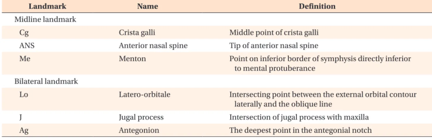
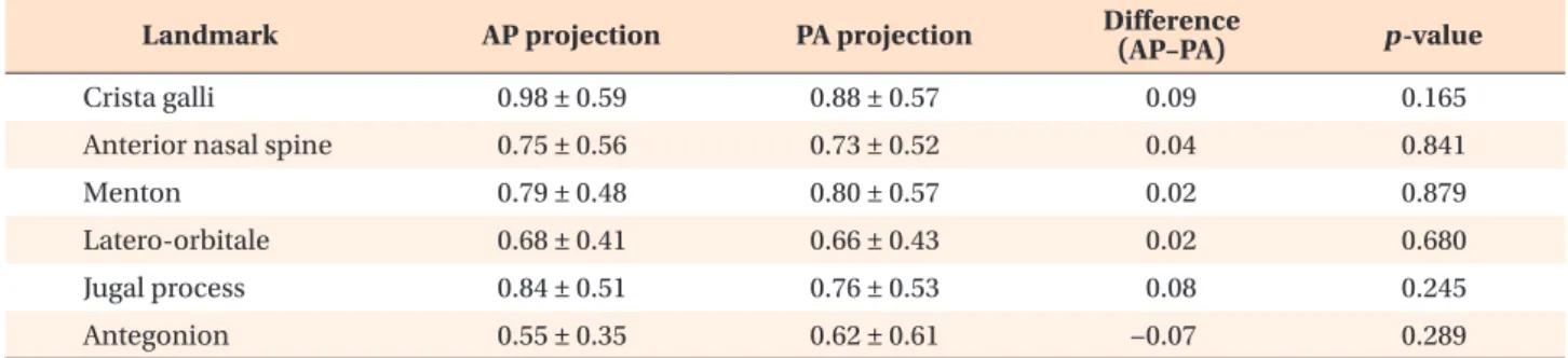
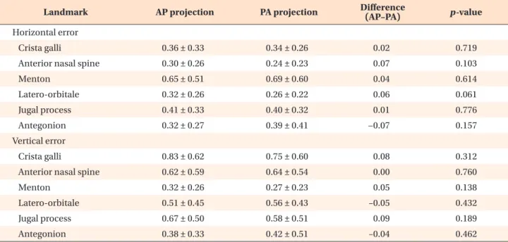
Objective: This in-vivo study aimed to compare landmark identification errors in anteroposterior (AP) and posteroanterior (PA) cephalograms generated from cone- beam computed tomography (CBCT) scan data in order to examine the feasibility of using AP cephalograms in clinical settings. Methods: AP and PA cephalograms were generated from CBCT scans obtained from 25 adults. Four experienced and four inexperienced examiners were selected depending on their experience levels in analyzing frontal cephalograms. They identified six cephalometric landmarks on AP and PA cephalograms. The errors incurred in positioning the cephalometric land- marks on the AP and PA cephalograms were calculated by using the straight-line distance and the horizontal and vertical components as parameters. Results: Com- parison of the landmark identification errors in CBCT-generated frontal cephalo- grams revealed that landmark-dependent differences were greater than experience- or projection-dependent differences. Comparisons of landmark identification errors in the horizontal and vertical directions revealed larger errors in identification of the crista galli and anterior nasal spine in the vertical direction and the menton in the horizontal direction, in comparison with the other landmarks. Comparison of landmark identification errors between the AP and PA projections in CBCT-gen- erated images revealed a slightly higher error rate in the AP projections, with no inter-examiner differences. Statistical testing of the differences in landmark identi- fication errors between AP and PA cephalograms showed no statistically significant differences for all landmarks. Conclusions: The reproducibility of CBCT-generated AP cephalograms is comparable to that of PA cephalograms; therefore, AP cepha- lograms can be generated reliably from CBCT scan data in clinical settings.

[Korean J Orthod 2019;49(1):41-48]

Key words: Posteroanterior cephalogram, Anteroposterior cephalogram, cone- beam computed tomography

Eui-Ri Na

a

Hussein Aljawad

b

Kyung-Min Lee

b

Hyeon-Shik Hwang

b

a

Department of Periodontology, School of Dentistry, Chonnam National University, Gwangju, Korea

b

Department of Orthodontics, School of Dentistry, Chonnam National University, Gwangju, Korea

Received April 11, 2018; Revised June 22, 2018; Accepted July 18, 2018.

Corresponding author: Kyung-Min Lee.

Associate Professor, Department of Orthodontics, School of Dentistry, Chonnam National University, 33 Yongbong-ro, Buk-gu, Gwangju 61186, Korea.

Tel +82-62-530-5864 e-mail [email protected]

How to cite this article: Na ER, Aljawad H, Lee KM, Hwang HS. A comparative study of the reproducibility of landmark identification on posteroanterior and anteroposterior cephalog- rams generated from cone-beam computed tomography scans. Korean J Orthod 2019;49:41-48.

© 2019 The Korean Association of Orthodontists.

This is an Open Access article distributed under the terms of the Creative Commons Attribution Non-Commercial License (http://creativecommons.org/licenses/by-nc/4.0) which permits unrestricted non-commercial use, distribution, and reproduction in any medium, provided the original work is properly cited.

pISSN 2234-7518 • eISSN 2005-372X

https://doi.org/10.4041/kjod.2019.49.1.41

(2)

INTRODUCTION

Cephalometric radiography can be used for a wide variety of orthodontic applications, such as understand- ing craniofacial growth and development, analyzing the association between craniofacial anatomy and the den- tal arch, establishing a treatment plan, and evaluating therapeutic efficacy.

1

In particular, frontal cephalograms provide useful data for analysis of dentoskeletal asym- metries, including horizontal maxillomandibular discrep- ancies and maxillary bone inclination.

2-4

Frontal cephalograms can be obtained in the antero- posterior (AP) or posteroanterior (PA) projections ac- cording to the direction of incident radiation, and PA cephalograms are commonly used for landmark iden- tification. PA cephalograms offer advantages over AP cephalograms for landmark identification because the anterior facial structures, which are regions of interest (ROI), are closer to the film and hence require less mag- nification than the structures farther from the film, thus mitigating the penumbra phenomenon

5

and yielding clearer images.

For this reason, frontal cephalograms are obtained in the PA projection in clinical settings. For orthognathic surgical simulation, however, AP cephalograms are re- quired for image synthesis using frontal cephalograms and corresponding facial images, which are used to generate computer simulations of the patient’s frontal facial photographs; these simulations are used to predict facial soft tissue changes, because AP cephalography has the same projection mode as facial photography. Despite this necessity, there is still a remarkable lack of relevant research and treatment in this field, because obtaining an additional frontal cephalogram in the AP projection only for the purpose of image synthesis is not easy in clinical practice.

The recently developed cone-beam computed tomog- raphy (CBCT) technique

6

is widely used in dentistry. For example, CBCT images reconstructed in three dimensions are examined from all directions for diagnostic analysis of impacted teeth or maxillofacial morphology. More- over, algorithms have been developed to easily generate various types of two-dimensional (2D) images, including cephalograms, from CBCT scan data. Studies have re- ported the use of CBCT-generated lateral cephalometric radiographs

7-10

or frontal cephalometric radiographs,

7,11,12

as well as the results of reliability testing for these im- ages.

In addition to lateral cephalograms or frontal PA cephalograms, the methods proposed in these studies can also be used to easily generate frontal AP cephalo- grams from CBCT scan data without additional exposure to radiation. As the first of its kind, this study examines the feasibility of using AP cephalograms for anatomical

landmark identification by assessing its reproducibility.

To this end, landmark identification errors were com- pared between PA and AP cephalograms generated from CBCT scan data in clinical settings.

MATERIALS AND METHODS

The present study was approved by Institutional Re- view Board of Chonnam National University Dental Hos- pital, Gwangju, Korea (CNUDH-2015-005). Orthodontic patients with both PA cephalograms and CBCT scans from their initial visit were enrolled. Participants with missing teeth and restorations with crowns or bridges were excluded. Twenty-five orthodontic patients with both PA cephalograms and CBCT scans from their initial visit were selected by assessing the data collected by the orthodontic department. CBCT scan data were obtained using a CBCT scanner (Alphard Vega; Asahi Roentgen Ind. Corp., Kyoto, Japan) under the following condi- tions: 80 kV, 5 mA, 0.39 × 0.39 × 0.39 mm voxel size, and a 200 × 179 mm field of view. CBCT scanning was performed using the embedded reference ear plug (REP)

13

and head posture aligner (HPA)

14

to ensure standardized volume orientation by constructing a reference axis for postural adjustment in subsequent CBCT volume im- ages.

AP and PA cephalogram generation

Digital Imaging and Communications in Medicine (DICOM) files obtained with CBCT scanning were loaded on the three-dimensional imaging computer program OnDemand3D

TM

(Cybermed Inc., Seoul, Korea) and re- constructed as volume images. The cephalogram was aligned to the reference position using the right and left ball markers in the REP and the wire indicator in the HPA. More specifically, the indicators of the right and left ear rod centers were positioned on their respec- tive ball markers on the screen of the “X-ray generator”

menu such that the virtual central ray passed through

both ball markers, and the posture in the cephalogram

was adjusted by vertically rotating it around the two

markers such that the HPA wire indicator was horizon-

tally aligned in the AP projection. When the posture was

aligned to the reference position, frontal cephalograms

were generated in both AP and PA projections, with the

subject facing forward and backwards with reference to

the virtual central ray, respectively. The same perspec-

tive view as in actual frontal cephalometric radiographs

was implemented by entering 150 cm and 15 cm as the

camera-to-film and ear rod-to-film distances, respec-

tively, when configuring the X-ray generator environ-

ment (Figure 1).

(3)

Landmark identification

In this study, which was conducted to compare the reproducibility of landmark identification between AP and PA cephalograms, the crista galli (Cg), anterior na- sal spine (ANS), and menton (Me) were used as midline landmarks, and the latero-orbitale (Lo), jugal process (J), and antegonion (Ag) were used as bilateral landmarks.

Four orthodontists experienced in landmark identifica- tion on frontal cephalograms (≥ 100 cases) and four general dentists were assigned to the experienced and inexperienced examiner groups, respectively. The exam- iners were provided with the definitions of the six ceph- alometric landmarks, as presented in Table 1, to ensure clear understanding of each landmark position. They performed landmark identification on 50 cephalometric radiographs (25 AP and 25 PA cephalograms) loaded on the analysis program V-ceph 6.0 (Osstem, Seoul, Korea).

The landmark positions estimated on each image were saved as x, y coordinates (Table 1).

Comparison of landmark identification errors in AP and PA cephalograms

Quantitative comparison of landmark identification errors in the AP and PA cephalograms was performed by

setting the overall mean estimate of each landmark as its best estimate

15

and defining the landmark identifica- tion error as the difference between the best estimate and the corresponding landmark identification per- formed by each examiner. The inter-examiner error was determined by setting the mean estimates of the two groups (four experienced vs. four inexperienced exam- iners) as their respective best estimates and calculating the distance from the best estimate to each landmark identification. In addition to calculating the straight- line distance to the best estimate as the error at each landmark, horizontal and vertical errors were also calcu- lated by breaking down the straight-line distance into the horizontal and vertical components in order to gain a more accurate understanding of error patterns.

Statistical analysis

SPSS ver. 17.0 (SPSS Inc., Chicago, IL, USA) was used for statistical analysis. The averaged errors of the experi- enced and unexperienced examiner groups were defined as their respective errors, and the differences in errors between the AP and PA cephalograms at each landmark in terms of the straight-line distance and its horizontal and vertical components were obtained using the means

A B

Figure 1. Frontal cephalo- grams generated from cone- beam computed tomography scan data using the OnDe- mand3D program (Cybermed Inc., Seoul, Korea). A, Antero- posterior projection; B, pos- tero-anterior projection.

Table 1. Definitions of the frontal cephalometric land marks used in this study

Landmark Name Definition

Midline landmark

Cg Crista galli Middle point of crista galli

ANS Anterior nasal spine Tip of anterior nasal spine

Me Menton Point on inferior border of symphysis directly inferior

to mental protuberance Bilateral landmark

Lo Latero-orbitale Intersecting point between the external orbital contour laterally and the oblique line

J Jugal process Intersection of jugal process with maxilla

Ag Antegonion The deepest point in the antegonial notch

(4)

and standard deviations calculated for 25 AP cephalo- grams and 25 PA cephalograms. Additionally, paired t- test was performed to assess the statistical significance of each difference thus obtained.

RESULTS

Error pattern in landmark identification on frontal ce- pha lograms

The landmark identification errors on frontal cepha- lograms ranged between 0.5 and 1.2 mm depending on landmark position, irrespective of experience status (experienced vs. unexperienced examiners) and projec- tion mode (AP vs. PA). Thus, error occurrence tended to depend on the inter-landmark differences rather than inter-examiner (experienced or unexperienced) or inter- projection (AP or PA) differences, with the smallest and greatest differences incurred at the Ag and Cg, respec- tively (Tables 2 and 3).

The analysis of landmark identification errors in the horizontal and vertical directions showed no significant differences between the errors in the horizontal and ver- tical directions at the bilateral landmarks. However, the midline landmarks tended to show larger errors in the

horizontal or vertical directions, with the Cg and ANS showing greater errors in the vertical direction and the Me in the horizontal direction, in comparison with the other landmarks (Tables 4 and 5).

Comparison of errors between the AP and PA cephalo- grams

Comparison of landmark identification errors between AP and PA cephalograms revealed that larger errors tended to occur in AP cephalograms and were more markedly incurred by experienced examiners, who per- formed better on PA cephalograms. However, the differ- ences did not reach statistical significance at any of the landmarks (Tables 2 and 3).

Each error was compared in terms of its horizontal and vertical components as well. As in the straight-line distance, larger landmark identification errors were made on AP cephalograms in both horizontal and vertical di- rections. Particularly large horizontal and vertical errors occurred at the Lo and Ag, respectively. Errors at the Ag were incurred by only unexperienced examiners, whereas both experienced and unexperienced examiners incurred larger horizontal errors at the Lo with respect to those at the other landmarks. However, none of the differences

Table 2. Landmark identification errors (mm) of experienced examiners

Landmark AP projection PA projection Difference

(AP–PA) p-value

Crista galli 0.98 ± 0.59 0.88 ± 0.57 0.09 0.165

Anterior nasal spine 0.75 ± 0.56 0.73 ± 0.52 0.04 0.841

Menton 0.79 ± 0.48 0.80 ± 0.57 0.02 0.879

Latero-orbitale 0.68 ± 0.41 0.66 ± 0.43 0.02 0.680

Jugal process 0.84 ± 0.51 0.76 ± 0.53 0.08 0.245

Antegonion 0.55 ± 0.35 0.62 ± 0.61 −0.07 0.289

Values are presented as mean ± standard deviation or data only.

The errors were evaluated in frontal cephalograms obtained with anteroposterior (AP) and posteroanterior (PA) projections (n

= 25).

Table 3. Landmark identification errors (mm) of inexperienced examiners

Landmark AP projection PA projection Difference

(AP–PA) p-value

Crista galli 1.15 ± 0.84 1.18 ± 0.82 −0.03 0.796

Anterior nasal spine 0.87 ± 0.60 0.96 ± 0.72 −0.08 0.378

Menton 0.73 ± 0.39 0.81 ± 0.56 −0.07 0.247

Latero-orbitale 0.93 ± 0.60 0.89 ± 0.59 0.04 0.612

Jugal process 0.94 ± 0.77 0.83 ± 0.73 0.12 0.223

Antegonion 0.60 ± 0.58 0.52 ± 0.37 0.08 0.225

Values are presented as mean ± standard deviation or data only.

The errors were evaluated in frontal cephalograms obtained with anteroposterior (AP) and posteroanterior (PA) projections (n

= 25).

(5)

in errors between AP and PA cephalograms reached sta- tistical significance, even including the Ag and Lo (Tables 4 and 5).

DISCUSSION

To predict the soft tissue changes induced by or- thognathic surgery, it is necessary to synthesize an im- Table 4. Landmark identification errors (mm) of experienced examiners in horizontal and vertical directions

Landmark AP projection PA projection Difference

(AP–PA) p-value

Horizontal error

Crista galli 0.36 ± 0.33 0.34 ± 0.26 0.02 0.719

Anterior nasal spine 0.30 ± 0.26 0.24 ± 0.23 0.07 0.103

Menton 0.65 ± 0.51 0.69 ± 0.60 0.04 0.614

Latero-orbitale 0.32 ± 0.26 0.26 ± 0.22 0.06 0.061

Jugal process 0.41 ± 0.33 0.40 ± 0.32 0.01 0.776

Antegonion 0.32 ± 0.27 0.39 ± 0.41 −0.07 0.157

Vertical error

Crista galli 0.83 ± 0.62 0.75 ± 0.60 0.08 0.312

Anterior nasal spine 0.62 ± 0.59 0.64 ± 0.54 0.00 0.760

Menton 0.32 ± 0.26 0.27 ± 0.23 0.05 0.138

Latero-orbitale 0.51 ± 0.45 0.56 ± 0.43 –0.05 0.432

Jugal process 0.67 ± 0.50 0.58 ± 0.51 0.09 0.189

Antegonion 0.38 ± 0.33 0.42 ± 0.51 –0.04 0.462

Values are presented as mean ± standard deviation or data only.

The errors were evaluated in frontal cephalograms obtained with anteroposterior (AP) and posteroanterior (PA) projections (n

= 25).

Table 5. Landmark identification errors (mm) of inexperienced examiners in horizontal and vertical directions

Landmark AP projection PA projection Difference

(AP–PA) p-value

Horizontal error

Crista galli 0.30 ± 0.25 0.36 ± 0.29 −0.06 0.085

Anterior nasal spine 0.30 ± 0.22 0.28 ± 0.24 0.02 0.575

Menton 0.60 ± 0.41 0.69 ± 0.60 −0.08 0.246

Latero-orbitale 0.36 ± 0.29 0.29 ± 0.23 0.07 0.061

Jugal process 0.38 ± 0.34 0.35 ± 0.33 0.03 0.573

Antegonion 0.29 ± 0.28 0.31 ± 0.29 −0.01 0.755

Vertical error

Crista galli 1.07 ± 0.87 1.06 ± 0.86 0.01 0.931

Anterior nasal spine 0.78 ± 0.62 0.86 ± 0.75 −0.08 0.402

Menton 0.31 ± 0.25 0.31 ± 0.21 0.01 0.880

Latero-orbitale 0.79 ± 0.63 0.80 ± 0.61 −0.01 0.951

Jugal process 0.82 ± 0.75 0.69 ± 0.71 0.13 0.156

Antegonion 0.47 ± 0.56 0.36 ± 0.33 0.11 0.057

Values are presented as mean ± standard deviation or data only.

The errors were evaluated in frontal cephalograms obtained with anteroposterior (AP) and posteroanterior (PA) projections (n

= 25).

(6)

age from a cephalogram and a corresponding optical image of the patient’s face. This can be done only if the cephalogram has the same projection mode as the optical image. Since an optical image is obtained in the perspective view of the face, a CBCT-generated frontal cephalogram should also have the perspective view. Al- though many computer programs have been developed to derive 2D radiographs from CBCT-generated DICOM files, most of them generate images in a parallel projec- tion. In this study, OnDemand3D

TM

was used because it provides an algorithm for generating images in the per- spective view as well.

For the purpose of this study, which intended to compare the reproducibility of landmark identifica- tion on CBCT-generated frontal cephalograms in the AP and PA projections, it was important to ensure the same craniofacial posture for generating the AP and PA cephalograms. Unlike a lateral cephalogram, in which the relationships between the cephalometric landmarks do not undergo any significant changes when the cra- niofacial image is being vertically rotated, landmarks on a frontal cephalogram are known to undergo not only changes in the vertical direction, but also in the hori- zontal direction, extending or contracting according to the landmark-to-film distance.

16,17

To ensure alignment of the volume images to the same posture for subse- quent AP and PA cephalograms, REP and HPA were used for CBCT scanning in this study. When generating AP and PA cephalograms, the same posture can be ensured by establishing a reference axis with the right and left ear plug ball markers displayed on the CB volume image and horizontally controlling the HPA wire indicator.

The AP and PA cephalograms generated with the computer program were used for cephalometric land- mark identification. Four inexperienced and four experi- enced examiners identified six landmarks (Cg, ANS, Me, Lo, J, and Ag) on these cephalograms, and the identi- fication errors at each landmark were compared. The findings indicated that inter-landmark differences were greater than inter-projection (AP vs. PA) differences.

For example, assessments of the Ag involved smaller er- rors, whereas larger errors occurred in identifying the Cg and ANS. For a more detailed examination of the error patterns, the horizontal and vertical components of the errors were analyzed. Errors at the Cg and ANS mainly occurred in the vertical direction, and those at the Me mainly occurred in the horizontal direction. This may be due to the fact that all participating examiners were accustomed to identifying the Cg and ANS in the horizontal direction because they are commonly used for establishing the median reference line, but were less experienced in performing careful identification of these landmarks in the vertical direction. On the other hand, the examiners committed larger errors in the horizontal

direction when identifying the Me, presumably because its identification is usually performed along the contour of the mandible inferior cortical bone. El-Mangoury et al.

18

investigated landmark identification errors on fron- tal cephalograms using human subjects and dry skulls and reported landmark-specific directionalities. Likewise, Athanasiou et al.,

19

who investigated 34 types of land- mark identification errors using frontal cephalograms, reported that each landmark showed a specific direc- tionality according to its definition.

The error comparison between the CBCT-generated AP and PA cephalograms revealed slightly more errors in AP cephalograms. This is a natural result attribut- able to the disadvantage of AP cephalography due to the position of the ROI, i.e., the anterior facial area is farther from the film than in PA cephalography, which necessitates greater magnification of the structures and thus increases the penumbra phenomenon, inevitably resulting in diminished image clarity. For a more detailed understanding of the error patterns associated with AP cephalograms, errors were examined in the horizontal and vertical directions. As a result, the Lo and Ag were found to show greater horizontal and vertical errors, respectively, compared with other landmarks. While the vertical error at the Ag occurs due to inexperience, given that it involved only inexperienced examiners, errors at the Lo tended to be greater on AP cephalograms than on PA cephalograms in both experienced and inexperi- enced examiners. This may be explained by the fact that the oblique orbital line is anatomically positioned in the anterior facial area and thus appears wider in the hori- zontal direction in the AP projection mode than in the PA projection mode, resulting in greater horizontal er- rors at the Lo, the point at which the oblique orbital line meets the external orbital contour.

Despite the slightly higher error-proneness of AP cephalograms in comparison with PA cephalograms, no significant differences were found in statistical analysis at any of the landmarks. This implies that the repro- ducibility of landmark identification on frontal cepha- lograms in the AP projection is not lower than that in the PA projection. This high reproducibility of landmark identification on AP cephalograms is attributable to the progresses made in CBCT image processing technology and the development of computer algorithms.

20-22

The results of this study demonstrate the feasibility of

using CBCT scan data for generating frontal cephalo-

grams in the AP projection depending on clinical neces-

sity, because the reproducibility of landmark identifica-

tion on AP cephalograms is practically as high as that on

PA cephalograms. Image synthesis using similarly gener-

ated AP cephalograms and corresponding optical images

is expected to facilitate creation of a computer program

for predicting or simulating the changes in facial mor-

(7)

phology after orthodontic treatment or orthognathic surgery. As the pre- and post-treatment patient database grows in the future, frontal cephalogram simulation software can be developed for clinical applications, and the method presented in this study is expected to serve as the basis for building such a system.

CONCLUSION

The results of this study suggest that the reproducibil- ity of CBCT-generated AP cephalograms is comparable to that of PA cephalograms. Thus, AP cephalograms can be reliably generated from CBCT scan data in clinical settings.

CONFLICTS OF INTEREST

No potential conflict of interest relevant to this article was reported.

ACKNOWLEDGEMENTS

This study was supported by a grant (CRI17023-1) of Chonnam National University Hospital Biomedi- cal Research Institute. This research was supported by Basic Science Research Program through the Na- tional Research Foundation of Korea (NRF) funded by the Ministry of Science, ICT & Future Planning (NRF- 2014R1A1A1003559) and the Ministry of Education (NRF-2017R1D1A1B03032132).

REFERENCES

1. Broadbent BH. A new x-ray technique and its appli- cation of orthodontia. Angle Orthod 1931;1:45-66.

2. Mulick JF. Clinical use of the frontal headfilm. Angle Orthod 1965;35:299-304.

3. Ricketts RM, Bench RW, Hilgers JJ, Schulhof R. An overview of computerized cephalometrics. Am J Or- thod 1972;61:1-28.

4. Grummons DC, Kappeyne MA. A frontal asymmetry analysis. J Clin Orthod 1987;21:448-65.

5. Whaites E. Essentials of dental radiography and ra- diology. In: Whaites E, ed. X-ray equipment, films and processing. 3rd ed. London: Churchill Living- stone; 2002. p. 35-40.

6. Mozzo P, Procacci C, Tacconi A, Martini PT, Andreis IA. A new volumetric CT machine for dental imag- ing based on the cone-beam technique: preliminary results. Eur Radiol 1998;8:1558-64.

7. Farman AG, Scarfe WC. Development of imaging selection criteria and procedures should precede cephalometric assessment with cone-beam com- puted tomography. Am J Orthod Dentofacial Orthop

2006;130:257-65.

8. Moshiri M, Scarfe WC, Hilgers ML, Scheetz JP, Silvei- ra AM, Farman AG. Accuracy of linear measurements from imaging plate and lateral cephalometric images derived from cone-beam computed tomography. Am J Orthod Dentofacial Orthop 2007;132:550-60.

9. Kumar V, Ludlow J, Soares Cevidanes LH, Mol A. In vivo comparison of conventional and cone beam CT synthesized cephalograms. Angle Orthod 2008;78:

873-9.

10. Cevidanes L, Oliveira AE, Motta A, Phillips C, Burke B, Tyndall D. Head orientation in CBCT-generated cephalograms. Angle Orthod 2009;79:971-7.

11. van Vlijmen OJ, Berge SJ, Bronkhorst EM, Swennen GR, Katsaros C, Kuijpers-Jagtman AM. A comparison of frontal radiographs obtained from cone beam CT scans and conventional frontal radiographs of hu- man skulls. Int J Oral Maxillofac Surg 2009;38:773- 8.

12. Sun MK, Uhm GS, Cho JH, Hwang HS. Use of head posture aligner to improve accuracy of frontal cephalograms generated from cone-beam CT scans.

Korean J Orthod 2009;39:289-99.

13. Hwang HS, inventor. Chonnam University Industry- Academic Cooperation Foundation, assignee. Ear plug for forming reference axis in CT taking. Korean Patent 10-0884354. 2009 Feb 7.

14. Kim EH, Hwang HS. The validity of head posture aligner in posteroanterior cephalometry. Korean J Orthod 2000;30:543-52.

15. Leonardi RM, Giordano D, Maiorana F, Greco M. Ac- curacy of cephalometric landmarks on monitor-dis- played radiographs with and without image emboss enhancement. Eur J Orthod 2010;32:242-7.

16. Proffit WR. The search for truth: Diagnosis in surgi- cal orthodontic treatment. St. Louis: Mosby Year Book; 1996. p. 127-8.

17. Koh EH, Lee KH, Hwang HS. Effects of vertical head rotation on the posteroanterior cephalometric mea- surements. Korean J Orthod 2003;33:73-84.

18. El-Mangoury NH, Shaheen SI, Mostafa YA. Land- mark identification in computerized posteroanterior cephalometrics. Am J Orthod Dentofacial Orthop 1987;91:57-61.

19. Athanasiou AE, Miethke RR, Van Der Meij AJ. Ran- dom errors in localization of landmarks in postero- anterior cephalograms. Br J Orthod 1999;26:273- 84.

20. Eppley BL, Sadove AM. Computerized digital en- hancement in craniofacial cephalometric radiogra- phy. J Oral Maxillofac Surg 1991;49:1038-43.

21. Wiesemann RB, Scheetz JP, Silveira A, Farman TT,

Farman AG. Cephalometric landmark clarity in pho-

tostimulable phosphor images using pseudo-color

(8)

and emboss enhancements. Int J CARS 2006;1:105- 12.

22. Körner M, Weber CH, Wirth S, Pfeifer KF, Reiser MF,

Treitl M. Advances in digital radiography: physi-

cal principles and system overview. Radiographics

2007;27:675-86.

수치

Table 1. Definitions of the frontal cephalometric land marks used in this study
Table 2. Landmark identification errors (mm) of experienced examiners
Table 5. Landmark identification errors (mm) of inexperienced examiners in horizontal and vertical directions

참조

관련 문서

• 이명의 치료에 대한 매커니즘과 디지털 음향 기술에 대한 상업적으로의 급속한 발전으로 인해 치료 옵션은 증가했 지만, 선택 가이드 라인은 거의 없음.. •

After choosing the type of bike, the next step is the right bike size. the right size for you from

44 글의 첫 번째 문장인 The most important thing in the Boat Race is harmony and teamwork.을 통해 Boat Race에서 가장 중요한 것은 조 화와 팀워크임을

Now that you have the right bike for you, it is important to learn the right riding position.. A poor riding position can lead to injuries

44 글의 첫 번째 문장인 The most important thing in the Boat Race is harmony and teamwork.을 통해 Boat Race에서 가장 중요한 것은 조 화와 팀워크임을

웹 표준을 지원하는 플랫폼에서 큰 수정없이 실행 가능함 패키징을 통해 다양한 기기를 위한 앱을 작성할 수 있음 네이티브 앱과

_____ culture appears to be attractive (도시의) to the

- quadriceps tendon 이 슬개골 하연에서 tibial tuberocity에 부착.