Received: Jan. 10, 2020 ; Revised: Jan. 22, 2020 ; Accepted: Feb. 3, 2020
†
Corresponding author: Si-Young Kwak (KITECH) Tel: +82-31-8084-8801, Fax: +82-31-8083-8806 E-mail: [email protected]
Journal of Korea Foundry Society 2020. Vol. 40 No. 1, pp. 1~6 http://dx.doi.org/10.7777/jkfs.2020.40.1.1 pISSN 1598-706X / eISSN 2288-8381
© Korea Foundry Society, All rights reserved.
This is an Open-Access article distributed under the terms of the Creative Commons Attribution Non-Commercial License (http://creative- commons.org/licenses/by-nc/3.0) which permits unrestricted non-commercial use, distribution, and reproduction in any medium, provided the original work is properly cited.
ESPI 장비를 활용한 사형 주조품의 잔류응력 측정 및 주조 열응력 해석
곽시영 *,***,†· 남정호 **
*한국생산기술연구원 디지털제조공정그룹 수석연구원
**한국생산기술연구원 디지털제조공정그룹 연구원
***과학기술연합대학원대학교 한국생산기술연구원 캠퍼스 생산기술과(산업소재 및 스마트제조전공)
Residual Stress Measurement of Sand Casting by ESPI Device and Thermal Stress Analysis
Si-Young Kwak*,***,† and Jeong-Ho Nam**
*Digital Manufacturing Process Group, Korea Institute of Industrial Technology (KITECH), Siheung 15014, Republic of Korea
** Digital Manufacturing Process Group, Korea Institute of Industrial Technology(KITECH), Siheung 15014, Republic of Korea
***Department of Industrial Technology, University of Science and Technology (UST), Daejeon 34113, Republic of Korea
Abstract
Many studies involving a thermal stress analysis using computational methods have been conducted, though there have been rel- atively few experimental attempts to investigate thermal stress phenomena. Casting products undergo thermal stress variations during the casting process as the temperature drops from the melting temperature to room temperature, with gradient cooling also occurring from the surface to the core. It is difficult to examine thermal stress states continuously during the casting process. There- fore, only the final states of thermal stress and deformations can be detemined. In this study, specimens sensitive to thermal stress, were made by a casting process. After which the residual stress levels in the specimens were measured by a hole drilling method with Electron Speckle-Interferometry technique. Subsequently, we examined the thermal stresses in terms of deformation during the casting process by means of a numerical analysis. Finally, we compared the experimental and numerical analysis results. It was found that the numerical thermal stress analysis is an effective means of understanding the stress generation mechanism in casting products during the casting process.
Key words: Casting process, Residual stress, Hole drilling method, Electron speckle-pattern interferometry, Numerical thermal stress analysis
1. 서 론
오늘날, 컴퓨터 시뮬레이션을 이용한 용탕의 응고 및 유동 해석은 주조 공정 분야에서 광범위하게 수행되고 있다. 또한 주조 엔지니어는 주조 과정에서 열 변형으로 인한 결함(예:
큰 변형 및 균열 발생)을 제어하기를 원하기 때문에 주조 공정에서 열응력 해석을 요구하고 있다.
주조공정중에 제품은 몰드안에서 냉각되기 때문에 냉각중 의 열응력/열변형 상태를 관찰하기 힘들고 거의 최종 상태 에서 변형양상과 잔류응력을 측정할 수 있다. 그렇기 때문 에 컴퓨터 시뮬레이션에 의한 수치해법은 주조공정 중에 시간에 따른 열응력과 변형 양상을 파악할 수 있는 강력한 도구이다.
Tien 등[1]은 플레이트 및 실린더와 같은 간단한 형상에
대한 주조 분석에서 응고하는 동안 탄성 모델을 기반으로 열 응력 분석을 시도하였다. 그리고 냉각 초기 단계에서 고온 영역의 점도를 고려하기 위해 점성-플라스틱 분석이 시도되었 다[2,3]. Song 등[4]은 변형으로 인한 주형과 제품의 접촉 문제와 에어 갭 효과를 고려하려고 하였다. 주조공정에서의 수치응력 분석에 대한 리뷰는 Tomas[5]에 의해 자세히 검토 되었다.
본 연구에서는 제품과 주형의 접촉 효과와 주조 열응력 현 상을 잘 나타내는 시편을 설계하여 2가지 재질(CrMoSC1, GC25)의 시편을 제작하고 ESPI (Electronic Speckle-Pattern Interferometry) 장비를 활용하여 주조시편의 표면 잔류응력 측정 실험을 수행하였다. 또한 주조공정을 모사하는 열응력 해석을 수행하고 주조제품의 잔류응력이 크게 나타나는 특 정 위치에서의 예측된 잔류응력을 시험결과와 비교, 검토하 였다.
2. Experimental Method 2.1 주조 시편 제작
실험에 사용된 모델은 주조 시 큰 온도의 변화에 따라 해 석 모델의 수직 종방향(y방향)으로 강한 인장 및 압축 열응
력을 나타낼 수 있도록 설계되어 실험과 해석의 결과를 비교 하고 검증하기가 용이하도록 고안되었으며 FIg. 1에 그 형상 과 크기를 나타내었다.
본 연구에서는 CrMo 합금강 및 회주철 2가지 재질의 시 편을 제작하였다. 두 재료의 주형은 모두 사형을 적용하였고 재질의 조성과 주조조건은 Table 1에 나타내었다.
2.2 잔류응력 측정방법
전통적으로 잔류응력의 측정은 측정부위에 스트레인게지를 붙이고 드릴 등을 이용해 홀을 가공하여 발생한 스트레인 을 역계산하여 원래 있던 잔류 응력값을 추정하게 된다.
본 연구에서는 스트레인 게이지 대신 잔류응력 측정을 위해 Fig. 3과 같이 우크라이나의 파톤 연구소에서 개발한 ESPI (Electronic Speckle-Pattern Interferometry)[6,7]를 적용한 장비와 홀드릴링 방법을 조합하여 주조품의 표면 잔류응력을 측정하였다.
잔류응력 측정 실험은 다음과 같은 실험 절차에 따라 시험 이 이루어진다.
1) 시편의 잔류응력을 측정할 위치를 결정한다.
2) 직경 1-2mm의 드릴 공구를 드릴 머신에 장착하고 요 구되는 깊이만큼 설정한다.
Fig. 3.
Electron Speckle Interfero-meter device for residual stress measure (E.O. Paton Electric Welding Institute).Fig. 1.
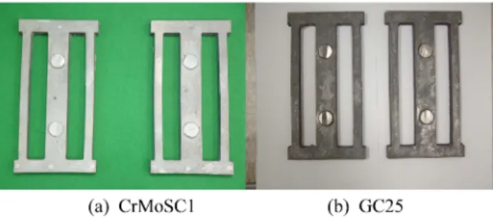
Dimension and casting design of the specimen.Fig. 2.
Specimens after casting process for residual stress measure- ment.Table 1.
Materials, chemical composition and casting condition of the specimens.Specimen Material Chemical Composition
Pouring Temperature
1 CrMo Steel
(CrMoSC1)
0.22% C 0.42% Si 0.7% Mn 0.93% Cr 0.2% Mo
1600[℃]
2 Gray Iron
( GC25)
3.4% C 2.0% Si 0.8% Mn
1350[℃]
3) 기준면 위에 잔류응력 측정기를 장착하고 잔류응력 측 정면의 초기 전자스페클 패턴 상태를 컴퓨터에 입력, 저장 한다.
4) 잔류응력 측정기를 탈착하고 미리 설정한 깊이의 구멍 을 뚫는다.
5) 측정면에 잔류응력 측정기를 다시 장착하고 측정면의 전자스페클 패턴을 컴퓨터 메모리에 저장, 상태변화 정보를 얻는다.
6) 재료 물성치와 얻어진 패턴 정보를 이용하여 잔류응력 을 계산한다.
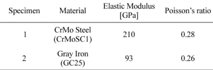
잔류응력 측정에 사용된 각 재료의 물성치는 Table 2와 같다[8,9].
3. Numerical Method
본 연구에서는 자체개발한 FDM/FEM 하이브리드 수치 해 석 기술을 사용 하였다(열전달해석을 위한 Finate Difference Method와 열응력 해석을 위한 Finite Element Method). 일 반적으로 FDM과 FEM 요소망은 일치하지 않으므로 FDM 요소망상에서 열전달을 통해 구한 온도 필드 데이터는 열응 력 분석을 위한 FEM 요소망으로 데이터 변환이 필요하다.
따라서 선형 보간에 기반한 효율적인 데이터 변환 절차가 개발되었다. FDM/FEM 하이브리드 방법 및 데이터 변환 절차에 대한 자세한 내용은 저자의 논문[10]을 참조할 수 있다.
해당 시편의 특정 위치(잔류응력 측정점)에서의 실험값과 해석 결과값을 비교, 검토하기 위해 열응력 해석을 수행하였
으며 해석의 효율을 위해 시편의 형상을 1/4로 모델링하였 다. FIg. 4에 해석에 사용된 모델의 유한 요소망을 보여 주고 있다.
4. 결과 및 비교 4.1 주조시험결과
FIg. 5 및 Fig. 6은 주조 후 시편의 사진으로 시편 1(CrMo steel)과 시편 2(Gray iron)의 변형 및 균열 결함을 잘 보여 주고 있다. 시편은 열응력에 민감하도록 설계되어 변형이 뚜 렷하고 모서리에 균열이 발생하였다.
Fig. 7은 주조 후 변형 형상을 분석하기 위한 측정 부위를 나타내며 변형 측정값은 Table 3에 나타 내었다. Fig. 5와 Fig. 6과 같이 시편은 섹션 B에서 볼록한 형상을 가지며 CrMo 합금강의 변형량은 회주철보다 약간 크다.
4.2 주조 잔류응력 해석결과
대표적으로 CrMo 합금강의 응고( 주입후 300초) 완료 시
Fig. 6.
Gray iron specimen after casting process.Fig. 5.
CrMo alloy steel specimen after casting process.Table 2.
Material properties for the residual stress measurement of the specimens.Specimen Material Elastic Modulus
[GPa] Poisson’s ratio 1 CrMo Steel
(CrMoSC1) 210 0.28
2 Gray Iron
(GC25) 93 0.26
Fig. 4.
FEM mesh for thermal stress analysis during casting.점과 주입 후 7,000초 이후의 잔류응력 분포를 Fig. 8에 나 타내었다. Fig. 8(a)의 응고 초기 해석결과는 수직의 종방향 (Y방향) 응력분포의 경우, 먼저 냉각하는 모델 외곽부에는 인 장응력이 발생하는 걸 볼 수 있다. Fig. 8(b)의 최종 잔류응 력은 모델 외곽부분에 압축응력이, 중심부에는 인장응력이 발 생함을 보여준다. 이는 현재 시편의 형상이 주조 시 강한 압 축과 인장응력을 나타낼 수 있도록 잘 고안된 모델임을 확인
할 수 있다.
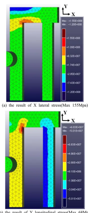
Fig. 9과 Fig. 10은 각 재질의 수평 횡방향(X 방향)과 수 직 종방향(Y 방향) 의 잔류응력 분포를 보여주고 있다. 잔류 응력의 크기는 CrMo 합금강이 GC25 회주철보다 2.5배~3배 크게 나타나며 이는 Table 2에서 보는바와 같이 탄성계수가 CrMo 강이 회주철보다 2.3배 크고, 주입온도가 더 높은데 기인하는 것으로 보인다.
Fig. 9.
Distributions of the residual stress at CrMo Steel at about 7,000 seconds.Fig. 7.
The measured sections to investigate deformation shape.Fig. 8.
Distributions of the longitudinal stress at specimen 1;(a) the results about 300 seconds( Max. 27 MPa), (b) the results about 7,000 seconds after pouring (Max. 190 Mpa).Table 3.
Measurement data of deformation appearance.Specimen 1 (CrMo steel)
Specimen 2 ( GC 25)
Section A [mm] 39.46 39.68
Section B [mm] 41.14 40.05
Section C [mm] 39.30 39.79
4.3 실험과 해석결과의 비교
잔류응력 측정점에서의 측정 응력값과 해석 응력값의 비교 를 위하여 해석 결과에서 나온 각 node의 해석값을 보간하 여 실험 측정점 위치의 잔류응력 값을 산출하였다. 실험 측 정점은 Fig. 11에 나타내었으며 Fig. 12와 Fig. 13에서는 그래프를 이용하여 각 측정점에서의 실험값과 해석값을 직접 대응시켜 값의 차이를 비교하였다.
Fig. 12(a)의 CrMo 합금상의 횡방향(X) 열응력 해석값은 -300 MPa에서 250 MPa이며 실험 결과는 외부 기둥부(측정 점 번호 16~20)과 일부 값을 제외하고는 잘 일치하였다.
Fig. 12(b)의 종방향(YY) 열응력 해석값은 -50MPa에서 150 MPa이며 실험 결과는 긴 기둥부(측정점 번호 10~20)를 제 외하고는 잘 일치하였다.
Fig. 13(a)의 GC25 회주철의 횡방향(X) 열응력 해석값은 -120 MPa에서 110 MPa이며 실험 결과는 일부 값을 제외 하고는 잘 일치하였다. Fig. 13(b)의 종방향(YY) 열응력 해 석값은 -40 MPa에서 40 MPa이며 실험 결과는 시뮬레이션 과 약간의 차이를 보여 주지만 응력값의 절대 값 자체가 적 어서 오차로 인한 응력값의 차는 크지 않았다.
5. 결 론
본 연구에서는 CrMo 합금강과 GC25 회주철로 만든 주조 시편에 대해 우크라이나 E.O parton 연구소에서 개발한 ESPI장비를 활용하여 잔류응력 측정실험을 수행하였다. 그리 고 실험 결과를 FDM/FEM 하이브리드 방법을 사용한 주조 열응력 해석결과와 비교하였다.
각 시편에 대해 주조 후 잔류응력을 측정하여 해석결과와 비교/검토한 결과 재질과 응력의 성분에 따라 차이는 있지만
Fig. 11. Locations of points of residual stress measurement.
Fig. 10. Distributions of the residual stress at GC25 at about 7,000
seconds.
약 70~90% 일치함을 보여 주었다. 이로써 주조 공정 중에 제품의 변화를 관찰하기 어려운 주조제품에서의 열응력/변형 에 대한 분석 도구로 주조 열응력 해석이 유용함을 확인할 수 있었다.
References
[1] R. H. Tien and V. Koump, ASME Journal of Applied Mechanics, “Thermal Stresses During Solidification on Basis of Elastic Model”, 36 (1969) 763-767.
[2] J. R. Williams, R. W. Lewis, and K. Morgan, Int. J. Num.
Methods in Engineering, “An elasto-viscoplastic thermal stress model with applications to the continuous casting of metals”, 14 (1978) 1-9.
[3] A. Yosida, S. Nagaki, and T. Inoue, J. Soc. Mat. Sci. Japan,
“Heat conduction and elastic-viscoplastic stresses during solidification of metallic materials”, 31-348 (1982) 897-901.
[4] R. Song, G. Dhatt and A. B. Cheikh, Int. J. Num. Methods in
Engineering, “Thermo-mechanical finite element model of casting systems”, 30 (1990) 579-599.
[5] B. G. Thomas, International Conference on Modeling of Casting & Solidification Process –VI, “Stress modeling of casting processses: An overview”, (1993) 519-534.
[6] L.M. Lobanov, V.A. Pivtorak, and N.G. Kuvshinsky, The Parton Welding Journal, “Diagnostics of structures of metallic and compositie materials using holography, electron speckle- interferometry and sherography”, 9-10 (2000) 72-78.
[7] Kwak SY and Hwang HY, Journal of Computational Design and Engineering,“Effect of heat treatment residual stress on stress behavior of constant stress beam”, 5-1 (2018) 137-143.
[8] High-Temperature Property Data: Ferrous Alloys, ASM International, OH (1988).
[9] ASM handbook, Properties and Selection: Irons, Steels, and High-Performance Alloys, ASM International, OH (1990) 628.
[10] Si HM, Cho CD and Kwak SY, J. Materials Processing Technology, “A hybrid method for casting process simulation by combining FDM and FEM with an efficient data conversion algorithm”, 133 (2003) 311-321.