Fabrication of Fe-TiC Composite by High-Energy Milling and Spark-Plasma Sintering
N. Q. Tuan, H. X. Khoa, N. H. Viet
a, Y. H. Lee, B. H. Lee, and J. S. Kim*
School of Materials Science and Engineering, University of Ulsan, San-29, Mugeo-2 Dong, Nam-Gu, Ulsan 680-749, Korea
aSchool of Materials Science and Engineering, Hanoi University of Science and Technology, No 1, Dai Co Viet Street, Hai Ba Trung dist, Hanoi, Vietnam
(Received July 31, 2013; Accepted October 1, 2013)
···
Abstract Fe-TiC composite was fabricated from Fe and TiC powders by high-energy milling and subsequent spark- plasma sintering. The microstructure, particle size and phase of Fe-TiC composite powders were investigated by field emission scanning electron microscopy and X-ray diffraction to evaluate the effect of milling conditions on the size and distribution of TiC particles in Fe matrix. TiC particle size decreased with milling time. The average TiC particle size of 38 nm was obtained after 60 minutes of milling at 1000 rpm. Prepared Fe-TiC powder mixture was densified by spark- plasma sintering. Sintered Fe-TiC compacts showed a relative density of 91.7~96.2%. The average TiC particle size of 150 nm was observed from the FE-SEM image. The microstructure, densification behavior, Vickers hardness, and frac- ture toughness of Fe-TiC sintered compact were investigated.
Keywords: Fe-TiC composite, high-energy milling, spark-plasma sintering
···
1. Introduction
Ceramic particulates have been widely used as rein- forcements for Fe-base composites to improve their mechanical properties. Among various ceramics such as TiC, TiB2, Al2O3, BN, and B4C, TiC has received much attentions due to its excellent properties like high hard- ness (Vickers hardness 28-35 GPa), high melting temper- ature (3067oC) and high modulus (Young’s modulus of elasticity 410-510 GPa) [1]. TiC also shows the good wettability and thermodynamic stability in molten Fe [2, 3].
The presence of hard TiC particles in the Fe-base matrix increases the wear resistance, elastic modulus, shear modulus, and creep property in Fe-TiC composites.
Various routes have been reported for fabrication of Fe- TiC composite which include powder metallurgy, con- ventional melting and casting, carbothermic reduction, combustion synthesis, aluminothermic reduction, elec- tron beam radiation, laser surface melting, and plasma spray synthesis route, etc. [4]
But researchers still meet limitations such as uniform distribution of fine TiC particles in the Fe matrix and the clean interface between them. Some attempts via normal melting and casting [4, 5] and carbothermic reduction [6, 7]
have been tried to fabricate in situ Fe-TiC composites with a uniform dispersion of TiC reinforcement. Com- bustion synthesis has also been used to synthesize Fe-TiC composite [8, 9]. Some authors reported that Fe-TiC composites produced by aluminothermic reduction [10], electron beam radiation, laser surface melting or plasma spray synthesis routes showed a submicron TiC particle and also some attractive mechanical properties [11-14], even with high fabrication cost.
Among these processes, powder metallurgy has been widely used to fabricate Fe-TiC composites [2-4, 15]
because of wide range of amount, size and homogeneous distribution of TiC reinforcement in Fe matrix, a high dislocation density, a small sub-grain size, and limited recrystallization that result in good mechanical properties.
Spark-plasma sintering (SPS) process has been known
*Corresponding Author : Ji Soon Kim, TEL: +82-52-259-2244, FAX: +82-52-259-1688, E-mail: [email protected]
<PM리뷰>
Fabrication of Fe-TiC Composite by High-Energy Milling and Spark-Plasma Sintering 339
as effective and fast densification process [16]. This pro- cess involves simultaneous action of pressure, tempera- ture and pulse electric current. It generates electric energy pulses in the gap between powders stacked in a die and directly applies the high energy of instantaneously gener- ated high temperature plasma for sintering of the mate- rial. Therefore, SPS is capable of sintering ceramic particulates-reinforced composites rapidly to its full den- sity at relatively low temperature in several minutes. A rapid consolidation is helpful to maintain ultrafine grain size and control the fine microstructure. However, little work has been done on the Fe-TiC composites using SPS process.
One of the main purposes of fabricating Fe-TiC com- posite is to use it as wear resistant material. It has been found that the wear resistance of the material increases with the decrease in particle size, the improvement of interfacial compatibility and also the increase of TiC vol- ume fraction. In the present work, Fe-TiC composite powder with 25 wt% of TiC was prepared by high- energy milling and Fe-TiC composite powder compacts were produced from the as-milled powder by spark- plasma sintering. The microstructure, particle size and phase of as-milled powder were investigated. The study also includes investigation of the microstructure, densifi- cation behavior, Vickers hardness, and fracture tough- ness of the Fe-TiC sintered compacts to confirm the effect of size and distribution of TiC particles on mechanical properties.
2. Experimental Procedure
TiC (99.5% purity, average particle size: 5 µm) and Fe (with 99% purity, ~200 µm) powders were used as start- ing materials in this study. The powders were mixed to have a composition of 75 wt% Fe and 25 wt% TiC. The powder mixture was milled by a high-energy planetary ball-mill (AGO-2). For comparison, the powder mixture was also milled in a low-energy simple horizontal ball- mill. Stainless steel vials and 5mm-balls were used as the milling media. A ball to powder ratio of 20:1 was used in all experiments. The vials were evacuated and filled with 0.3 MPa argon gas to prevent iron powder from oxida- tion during the milling process. The milling process was listed in Table 1.
The densification of as-milled Fe-TiC powders was performed with use of the SPS-515S system (Sumitomo Coal Mining Co., Japan). As-milled powder mixture was loaded into a cylindrical graphite die with 10 mm-inner diameter and were heated up with the rate of 50oC/min.
to 1000oC and then kept for 10 minutes under a constant pressure of 50 MPa in a vacuum chamber of 0.4 Pa.
Phase of Fe-TiC powder mixtures after milling were investigated by X-ray diffractometer (XRD) using CuKα radiation. The crystallite size of TiC particles was esti- mated by the Scherrer equation from XRD data. The microstructure of the as-milled powders and the sintered samples were observed and analyzed by using optical microscope and field emission scanning electron micro- scope (FE-SEM). The average particle size of TiC was determined by ImageJ software [17]. Hardness of all the sintered composites were measured by using Vickers’s hardness tester with 30 kg load. The micro-hardness of the individual phases in the sintered composites was determined using Vickers’s indentor with 50 g load. The average of ten measurements has been taken as the hard- ness of the material/individual phase. Indentation frac- ture toughness test was carried out by using Vickers’s indentor with 100 kg load. The length of cracks was measured by the optical microscopy and took a compari- son between specimens to evaluate the fracture tough- ness property [18, 19].
3. Results and Discussion
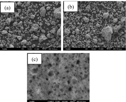
The morphology and topology of the milled Fe-TiC pow- ders prepared by high-energy milling at 1000 rpm with milling time of 10 and 60 minutes were shown in Fig. 1.
It is well known that cold welding and fracture are the two essential processes involved in the mechanical mill- ing process where powder particles are repeatedly flat- tened, cold welded, fractured, and re-welded [20]. The Table 1. Milling condition of Fe-TiC composite powders prepared in this study
Sample ID Mill Speed, rpm Time, min.
M1 AGO-2 1000 60
M2 AGO-2 1000 10
M3 AGO-2 300 60
M4 Simple ball mill 400 1440
Fe-TiC composite powders are composed of fine and agglomerated powder particles, as shown in Fig. 1 (a and b).
BSE (back-scattered electron) image of Fig. 1(c) shows the cross-section of the M1 powder. At this stage of mill- ing, the hard particles of TiC are randomly embedded into the deformed Fe soft matrix to form composite Fe- TiC powders. It is evident to see a typical nanocompos- ite material containing only the two starting phases of TiC (dark granular fine grains) in metallic Fe (matrix) with a uniform distribution of TiC particles. This is the typical microstructure of brittle-ductile material mixture mechanically treated by high-energy milling [20]. With use of ImageJ software [17], SEM image was processed to separating the dark area (TiC particles) and the bright area (Fe matrix). The average particle size of TiC was determined by using “Analyze Particles” function. The average particle size of TiC decreases from 184 nm to 38 nm with increasing the milling time from 10 minutes to 60 minutes.
XRD results of the as-milled powder mixtures are shown in Fig. 2. Two evident phases of Fe and TiC were detected and no other phases were found. Figure shows clearly that the high-energy milling affects the refine-
ment of particle size. By using the Scherrer equation from the peak at 41.7o the crystallite size of TiC rein- forcement was estimated, although this method may not be ideally applicable to the highly-deformed sample like milled powder. The results show that the crystallite size decreases from 14 nm (M2) to 7 nm (M1) with increas- Fig. 1. FE-SEM images of Fe-TiC powders prepared by high-energy milling: Secondary electron image of (a) M1 powder, (b) M2 powder and (c) back-scattered electron image of cross-section of M1 powder.
Fig. 2. XRD patterns of Fe-TiC powders of M1 and M2 which were prepared by high-energy milling at 1000 rpm for 10 (M2) and 60 (M1) minute, respectively.
Fabrication of Fe-TiC Composite by High-Energy Milling and Spark-Plasma Sintering 341
ing the milling time from 10 minutes to 60 minutes.
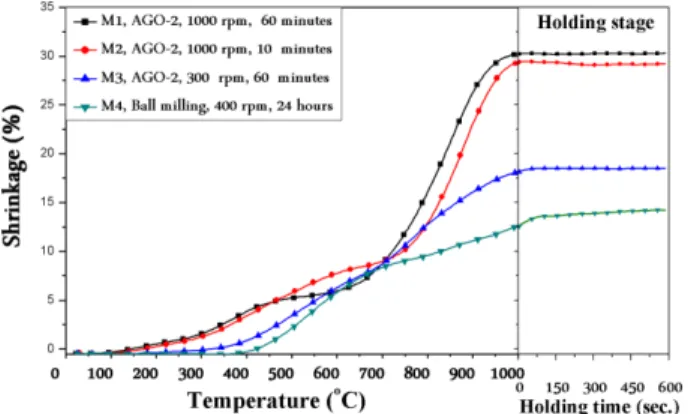
In our study, SPS is used for densification of milled powders. The changes in shrinkage during the SPS pro- cess are illustrated in Fig. 3. The shrinkage value of the samples M1 and M2 were nearly the same and much higher than M3 and M4 in all sintering stages. This dif- ference of shrinkage between M1-M4 powders seems to be resulted from the difference in the average particle size and the green density.
Sintered compacts of M1 and M2 composite powders
showed nearly the same relative density of 96.2% and 96.4%, respectively, which are relatively high values of sintered density in comparison with other conventional Fe-based PM products [21]. The relative densities of M3 and M4 powder compacts were 93.8% and 91.7%, respectively.
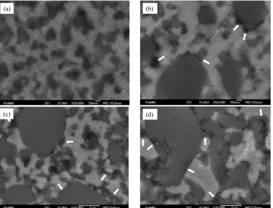
The particle size, shape and distribution of TiC parti- cles in Fe matrix of M1, M2, M3 and M4 sintered com- pacts are given as BSE images in Fig. 4. M1 shows ultrafine TiC particles with average size of 150 nm which are homogeneously distributed in the Fe matrix. Even though M2 reveals also relatively fine TiC particles with average size of ~300 nm in Fe matrix, the microstructure is not uniform as in M1. Some large TiC particles (~1 µm) remained in the matrix. On the M3 microstructure, the TiC particle size is not uniform; several large TiC particles retain the initial size (~ 5 µm), the average parti- cle size is ~1.3 µm.
To observe the microstructure of the matrix and the reinforced phase more clearly, the FE-SEM images at high magnification were obtained and given in Fig. 5.
The degree of reinforcement or improvement of mechani- cal properties still depends on strong bonding at the Fig. 3. Change in shrinkage of Fe-TiC composite powder
compacts during SPS process.
Fig. 4. FE-SEM images of polished cross-section of Fe-TiC sintered compacts: M1, (b) M2, (c) M3, and (d) M4.
matrix-reinforcement interface. It is obviously to see from Fig. 5(a) that cohesive interface between Fe matrix and TiC reinforcement was obtained by high energy mill- ing AGO-2 at 1000 rpm for 60 minutes. The interface between Fe matrix and TiC reinforcement get loose (as shown by arrow indication at interface) when the milling time or milling speed decreases in order of M2, M3 and M4, respectively.
Hardness measurements of the sintered compacts of M1, M2, M3 and M4 are presented in Table 2. The hard- ness increases in the order of M3, M4, M1, M2 com- pacts. This result is due to the higher relative density, uniform microstructure, and cohesive interface of rein- forcement and matrix of M1, M2 in comparison with M3, M4 composite compacts. The micro-hardness (HV0.5) val- ues of these composites are shown in Table 2. In M1 and
M2 sintered compacts, the hardness values were in the same range at any indentation point of the specimen. The values of hardness in M1, M2 powder compacts are nearly the same. But in the samples of M3, M4 sintered compacts, the separated areas of Fe rich area and TiC rich area showed a large different value of hardness. It seems due to inhomogeneous distribution of coarse TiC phases in Fe-matrix. The hardness of M1 compact, HV30 equivalent to 4.28 GPa, is in the hardness range of Fe-Ti- C (3.04GPa) and Fe-Ti-Cr-C (6.31 GPa) ferrous compos- ites, which can replace WC-Co materials for the applica- tion like mechanical seals [22].
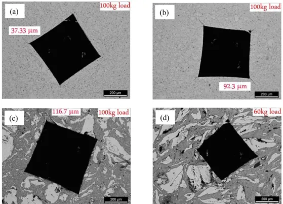
Fig. 6 shows optical micrographs showing the indenta- tion edge and crack path resulted from Vickers indenta- tion at 100 kg load for M1, M2 and M3 sintered compacts, and 60 kg load for M4 sintered compact. Number of cracks and their length increase from M1 to M4 sintered compacts. Particularly, M4 powder compact shows many cracks in the edge and side even though it was less loaded with 60 kg. It seems not to be enough tough and thereby damaged. The uniform distribution of TiC nano- particles and high interfacial bonding between Fe and TiC in M1 powder compact might be the reason of the Fig. 5. FE-SEM images of polished cross-section of Fe-TiC sintered compacts given in Fig. 4 at higher magnification: (a) M1, (b) M2, (c) M3, and (d) M4.
Table 2. Vickers hardness of Fe-TiC sintered compacts
Samples M1 M2
M3 M4
Fe-rich area
TiC-rich area
Fe-rich area
TiC-rich area
HV30 436 451 344 330
HV0.5 585 579 384 512 355 760
Fabrication of Fe-TiC Composite by High-Energy Milling and Spark-Plasma Sintering 343
highly tough behavior.
4. Conclusions
TiC reinforced Fe-base composite powders were suc- cessfully produced by high-energy milling, a simple route which easily controls composition and particle size of TiC reinforcement. The milling investigation showed that the TiC particle size decreases significantly after high- energy milling process. The average TiC particle size of 38 nm was measured by Sherrer method from XRD analysis for the Fe-TiC composite powder milled for 60 minutes at 1000 rpm. TiC particles with average size of 150 nm were uniformly distributed and strongly bonded with Fe matrix in the spark-plasma-sintered compact with relative density of 96.2%. Vickers hardness of 436 HV and good fracture toughness behavior were con- firmed.
Acknowledgements
This work was supported by the National Research Foundation of Korea Grant funded by the Korean Gov- ernment (NRF-2012R1A1A2044930).
References
[1] Hugh O. Pierson: Handbook of Refractory Carbides and Nitrides: properties, characteristics, processing, and appli- cations, William Andrew Publishing/Noyes, 1996.
[2] T. K. Bandyopadhyay and K. Das: J. Mater. Sci., 39 (2004) 6503.
[3] E. Pagounis, M. Talvitie and V. K. Lindroos: Metall. Mater.
Trans. A, 27A (1996) 4171.
[4] Wang Jing and Wang Yisan: Materials Letters, 61 (22) (2007) 4393.
[5] B. S. Terry and O. S. Chinymakobvu: J. Mater. Sci. Lett., 10 (1991) 628.
[6] M. Razavi, M .S. Yaghmaee, M. R. Rahimipour, S. Salman, and R. Tousi: Int. J. Miner. Process, 94 (2010) 97.
[7] I. W. M. Brown and W. R. Owers: Current Applied Physics, 4 (2004) 171.
[8] K. S. Vecchio, J. C. Lasalvia, M. A. Meyers and G. T. Gray III: Metall. Trans. A, 23 (1992) 87.
[9] Y. Choi and S. W. Rhee: J. Mater. Sci., 28 (1993) 6669.
[10] L. L. Wang, Z. A. Munir and Y. M. Maximov: J. Mater.
Sci., 28 (1993) 3693.
[11] J. D. Ayers and R. J. Schaefer: Laser Application in Mate- rial Processing, Society of Photo-Optical Instrumentation Engineers, Bellingham, Washington, (1979) 57.
[12] J. Lee, K. Euh, J.C. Oh and S. Lee: Mater. Sci. Eng. A, 323 (2002) 251.
[13] A.Y. Fasasi, M. Pons, C. Tassin and A. Galerie: J. Mater.
Sci., 29 (1994) 5121.
Fig. 6. Optical micrographs of Fe-TiC sintered compacts after indentation showing the indentation edge and crack path: (a) M1, (b) M2, (c) M3, and (d) M4.
[14] R. Licheri, R. Orru, G. Cao, A. Crippa and R. Scholz: Ceram- ics International, 29 (2003) 519.
[15] Y. B. Liu, S. C. Lim, L. Lu, and M. O. Lal: Metal Matrix Composites, Woodhead Publishing, Madrid, (1993) 770.
[16] Roberto Orr, Roberta Licheri, Antonio Mario Locci, Alberto Cincotti, and Giacomo Cao: Materials Science and Engi- neering: R: Reports, 63(4-6) (2009) 127-287.
[17] http://rsbweb.nih.gov/ij/.
[18] G. D. Quinn and R. C. Bradt: J. Am. Ceram. Soc., 90 (2007) 673.
[19] F. Sergejev and M. Antonov: Comparative study on indenta-
tion fracture toughness measurements of cemented car- bides, Proc. Estonian Acad. Sci. Eng., 12 (2006) 388.
[20] C. Suryanarayana: Mechanical Alloying and Milling, Marcel Dekker publishing, New York, (2003) 83.
[21] R. M. German: Powder Metallurgy of Iron and Steel, John Wiley & Sons, Inc., New York, (1998) 385-396.
[22] R. M. Hathaway, P. K. Rohatgi, N. Sobczak, and J. Sobc- zak: Proc. Int. Conf. HIGH TEMPERATURE CAPIL- LARITY (Edited by N. Eustathopoulos and N. Sobczak), Cracow, Poland, (1997) 267.