Effects of intake flows on spray structure of a high pressure multi-hole injector in a second generation direct-injection
gasoline engine
제 2세대 직접분사식 가솔린 기관에서 고압다공연료분사기의 분무 형상에 대한 흡기유동의 영향
S. S. Kim and S. H. Kim 김성수․김순호
Key Words:Intake Flow(흡기유동), Swirl Flow(선회유동), Tumble Flow(텀블유동), Direct Injection Gasoline Engine(직접분사식 가솔린 기관), Spray Structure(분무형상)
요약:제 2세대 직접분사식 가솔린 기관에서 6공 연료분사기의 연료분무특성을 관찰하였다. 실험에 사용한 직 접분사식 가솔린 기관은 2개의 흡입밸브와 2개의 배기밸브를 갖는 텀블형 Spray Guided 연소실과 Quartz로 제 작된 실린더 라이너와 실린더 헤드 창으로 구성되어 있다. 선회유동을 유도하기 위하여 흡입매니폴드에 선회유 동 제어밸브를 부착하였다. 2차원 Mie 스캐터링 기법을 이용하여 연료분사시기, 연료분사압력과 실린더 내 유 동 및 냉각수 온도가 연료분무에 미치는 영향을 관찰하였다. 실험결과로는 흡기과정동안 흡기 선회유동은 분사 된 연료의 공간적 분포에 크게 작용하였고, 압축과정동안에는 텀블 및 선회유동의 영향이 흡기과정에 비해 크 지 않음을 확인하였다. 또한 성층연소를 위해서 압축과정에서 연료를 분사하는 경우 고압의 연료분사압은 분무 도달거리의 성장을 촉진시키나 상승하는 피스톤과 이로 인한 실린더 압력의 상승으로 분무도달거리의 성장이 억제됨을 확인할 수 있었다.
접수일 : 2007년 10월 11일, 채택확정 : 2007년 11월 13일 김성수(책임저자) : 신라대학교 자동차기계전자공학부 E-mail : [email protected], Tel : 051-999-5712 김순호 : 신라대학교 자동차기계전자공학부
1. Introduction
Direct-injection spark ignition (DISI) engines offer the best promise for simultaneous reduction of fuel consumption and exhaust emissions in gasoline engines. The wall-guided first generation injection systems, with swirl pressure atomizers have proved to offer lower fuel consumption of up to 20% in the case of stratified, overall-lean part-load operation, but not significant improvements in HC and NOx emissions.1)
Most recent researchers have focused on an alternative strategy to the wall- and air-guided mode of mixture preparation for producing stratified fuel mixtures, the so-called
spray-guided using a new generation fuel injection system with either central or side fuel injection2). Recently, a number of injector manufacturers have designed new high-pressure multi-hole injectors and outwards opening piezo injectors, referred to as 'second-generation' systems, on the expectation that they produce stable fuel sprays with fine fuel droplets independent of the time of fuel injection.
Multi-hole injectors have been studied due to their potential of achieving good fuel stratification, thus being able to extend the lean limit further.3) They also offer the highest possible flexibility in adapting the spray pattern layout to a particular combustion chamber design. Some detailed experimental investigations have been carried out and reported on the gasoline spray characteristics and mixture distribution in engines equipped with high-pressure multi-hole injectors at injection pressures up to 200bar and back pressures up to
12 bar.4~5) These studies confirmed that the overall spray angle relative to the axis of the injector is independent of injection and chamber pressure.
The effects of injection and chamber pressure on droplet velocities and diameter were also quantified. For late fuel injection during the compression stroke aiming at stratified overall lean mixtures, the elevated in-cylinder gas pressure/density reduces spray penetration and produces a more compact spray that can more easily be directed towards the spark plug. In addition, the investigations of identified the complex nature of the in-nozzle flow and, in particular, the development of different types of cavitations that can influence the stability of the emerging jet sprays.6)
Mixture preparation in direct injection engines is one of the most important processes in ensuring a successful DISI combustion system.
Preparing the desired mixture inside the combustion chamber over the full range of engine operating conditions is quite difficult, as the fuel/air mixing process is influenced by many time dependant variables.
In this study, the spray characteristics generated by a high pressure multi-hole injector have been examined as a function of injection timing, in-cylinder air charge motion, coolant temperature, and injection pressure using the Mie scattering technique. The engine configuration and experimental techniques for the present experiments are described in the following section, the results are presented and discussed in section 3, and the paper ends with a summary of the most important findings.
2. Experimental set-up
2.1 Engine design
The single cylinder research engine used in this study was designed for optical measurements and, as such, it offers good optical access, with its 4-valve modern pent roof cylinder head designed
(a) (b)
(c) (d)
Windows pocket
Pentroof windows Quartz liner Plenum
chamber
Injector
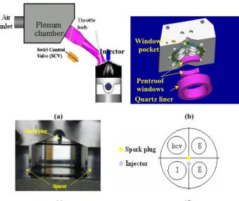
Fig. 1 Engine set up: (a) Schematic of engine set-up (b) Optical access arrangement; (c) Front view optical access (d) Cylinder head configuration
Table 1 Engine specifications
Description Specification Engine type Spray guided pent-roof
DISI engine Ports Tumble / var. swirl Cylinder (bore × stroke) 92 ㎜ × 95 ㎜
Compression ratio 10.5
Fuel injection pressure 7/15 ㎫ Injector 6 hole injector
to allow spray-guided operation. The optical engine set up is shown in Fig. 1 (a-d), and the engine configuration details are summarized in Table 1. As shown in Fig. 1a, downstream of the throttle valve there is a second valve installed at the inlet of one of the ports, named Swirl Control Valve (SCV). When this valve closed, in-cylinder swirl is generated. The position of this valve can be varied manually from fully open to close an external gauge controller. Without the swirl control valve, this cylinder head was designed to generate high tumble flows; and the TVRo (steady flow tumbling vortex) values measured were 1.38 for 1000 rpm in a steady flow rig test7). Optical access to the combustion chamber was provided from the side (vertical images) through a fused silica cylinder liner (Fig. 1b and 1c). As
can be seen in Fig. 1b, there are also two quartz windows fixed on both sides of the cylinder head to provide access to the pent roof area. The piston crown has a flat design so that an optical window can be fitted to obtain horizontal images.
The orientation of the injector and the spark plug is in the longitudinal arrangement shown in Fig.
1d; the line of the spark plug and the injector is in the middle of the pent roof between the intake and the exhaust valves. All tests were carried out without combustion where the engine was motored. Identification of the engine cycle and crank angle position was achieved by an optical pick up sensor mounted on the exhaust camshaft and a crankshaft encoder (Muirhead Vactric) which produced 1440 pulses per revolution, thus resulting in a resolution of 0.25 crank angle degrees.
2.2 Mie scattering system
The optical set-up was used for capturing Mie scattering images. The illumination of the spray was achieved by means of a xenon flash light directed via a couple of optical fibers to the area of interest. Qualitative and quantitative information of the spray was extracted from high-resolution forward illuminated images recorded with a non-intensified 12bit CCD PCO SensiCam camera, offering a resolution of 1024x1240 pixels and low readout noise, in conjunction with a Nikkor telescopic zoom lens (75-300mm 1/4.5-5.6). Imaging timing is controlled by the engine control system which has equipped with two general purpose triggers.
An activating cycle frequency of the image capturing and fuel injection was set in such a way to allow sufficient time (15s) for the xenon flash light to recharge fully.
To explore the spray pattern of a high pressure 6-hole injector, a variety of different operating modes and conditions were tested as shown in Table 2. The injection duration was kept at 1 ms for all the test conditions. Spray imaging was repeated 3 times for each time step of each test case. The spray cone angle and penetration that
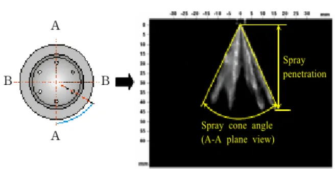
have been obtained from the Mie images regarding the multi-hole injector are defined and provided in Fig. 2; images taken in A-A plane view were used to obtain the spray cone angle.
The spray penetrations were measured from the nozzle tip to the maximum propagated point of jets.
Spray penetration
Spray cone angle (A-A plane view) A
A B B
Fig. 2 Injector nozzle and spray view
Table 2 Experimental conditions
Description Specification In-cylinder flow Tumble / var. swirl Coolant temperature 40°C/90°C Inlet air temperature 20°C
Fuel Iso-octane
Operating mode Homogeneous/stratified
For the investigation of in-cylinder spray characteristics, the injected sprays of 6-hole injector were visualized in B-B plane view at engine speed of 1000 rpm. There is a 0.2 ms delay between the injection trigger signal and the first appearance of a spray. Therefore, spray evolution images were captured from 0.3ms ASOI to 1.1ms ASOI by the time interval of 0.1ms.
3. Results and discussion
3.1 Early injection for homogeneous charge Multi-hole injectors are known to have stable spray structure under various operating conditions. Overall spray cone angle remains close to the nominal design value with increasing chamber pressure; thus early and late injection during an engine’s cycle appear to have almost identical spray shape, affecting only spray’s
penetration in the combustion chamber.
Homogeneous operation dictates early injection of the fuel during the induction stroke.
A selection of early injection timing includes injection of fuel at 60°CA, 90°CA and 120°CA after induction TDC. From the previous LDV measurement of in-cylinder flow under ‘SCV open’ or tumble flow condition7), it was realized that high velocities were generated during the intake process, rising to a maximum between 60°CA and 120°CA and then decreasing in response to the piston motion. During this period, the incoming high velocity annular air-jet flows were directed axially towards the down-going piston and radially towards the exhaust. The results also showed that the generated swirl flow was not strong and not well defined with respect to cylinder axis. The injected spray pattern during the intake stroke with ‘SCV open’ can be strongly affected by the tumble motion and its variation will result from the turbulence of the swirl motion.
Evolution of spray pattern at different injection timing of 60°CA, 90°CA and 120°CA after induction TDC, with the SCV fully closed (maximum swirl), are displayed in Fig. 3. As can be seen, there are two distinct features in the spray structures, one is that the multiple spray plumes from the multi-hole nozzle can not be discriminated and the second is a clear tilt of the overall spray towards the exhaust side and down the same as that of the incoming annular air jet trajectory. The merging or smearing of the spray plumes is taking place as soon as the fuel plumes are generated from the nozzle. This is because the plumes are subjected to a strong intake flow with high tumble and swirl velocities, and high turbulence. As a result the smaller and slower droplets will be dispersed rapidly under highly turbulent and swirling flow causing the separated injected fuel plumes to smear together. It is also clear from the images that the tilt of the overall spray is in the direction of the intake cross-flow.
These effects are more evident when the elapsed
time goes over 0.7ms ASOI (After Start Of Injection), the whole spray is now inclined towards the downstream and further more the fuel droplets of tip edge start to be separated from the main plumes jet towards the cross-flow direction; the latter effect can be due to high swirling and turbulence. The extent of the separation increase according to the elapsed time after start of injection and those of 90°CA and 120°CA SOI are more pronounced than that of
SOI 0.5ms ASOI (=3°CA)
0.7ms ASOI (=4.2°CA)
0.9ms ASOI (=5.4°CA)
1.1ms ASOI (=6.6°CA)
60
90
120
Colour index
0 0.5 1
Fig. 3 Mie images during the intake stroke with swirl flow
SOI 0.5ms ASOI
(=3°CA) 0.7ms ASOI
(=4.2°CA) 0.9ms ASOI
(=5.4°CA) 1.1ms ASOI
(=6.6°CA)
60
90
120
Colour index
0 0.5 1
Fig. 4 Mie images during the intake stroke with tumble flow
60°CA. At 0.9-1.1ms ASOI, the spray tilt is even more recognizable with downstream injected fuel droplets are largely distributed in the cross-flow direction. This phenomenon represents the promotion of the injected fuel distribution through the combustion chamber. The swirl flow activates the spatial advantage of multi-hole nozzle to accommodate the homogeneous charge mixture.
At the elapsed time of 1.1ms, small portion of the separated fuel droplets reaches to the cylinder wall which is undesirable. But the period that the piston returns to the same position of the compression stroke will be over 30ms and it would be enough to vaporize.
The spray evolution with tumble flow at start of injection of 60°CA, 90°CA and 120°CA after induction TDC are displayed in Fig. 4. Like the spray pattern under the swirl flow, the multiple spray plumes can not be distinguished for the same reasons. The injected fuel spray plumes can’t avoid the strong influence of the incoming air cross-flow during the intake valve open due to the injector position in the cylinder head.
Generally the tumble flow does not deflect the spray pattern as strong as that with swirl flow and that there is not any fuel droplets separation phenomenon the latter suggests no impingement on the liner. The larger spray deflection and the droplets separation with swirl flow, as seen in Fig. 3, clearly suggest the presence of centrifugal force acting on fuel droplets away from the centre of cylinder.
Overall comparison with the spray patterns under the flow of Fig. 3 indicates that the spatial distribution of the injected fuel spray under the tumble flow is apparently less than that of swirl flow especially from the elapsed time of 0.7ms.
Therefore for a well distributed, homogenized and stoichiometric mixture, it is confirmed that the swirl flow is more important to be generated in cylinder than the tumble flow. Comparison with other spray patterns at different start of injection shows that the spray pattern at 90°CA after induction TDC is more affected by the tumble cross-flow.
3.2 Late injection for stratified charge
The concept of stratification needs to be clarified according to engine design. At the time of ignition, an ignitable mixture cloud should be around the vicinity of the spark plug. This mixture cloud could be slightly rich in fuel locally, while the remaining volume of the combustion chamber is occupied by air. The size of the mixture cloud increases with increasing engine load and the load is controlled quantitatively by the amount of fuel injection.
SOI 0.5ms ASOI
(=3°CA) 0.7ms ASOI
(=4.2°CA) 0.9ms ASOI
(=5.4°CA) 1.1ms ASOI
(=6.6°CA)
270
285
300
Colour index
0 0.5 1
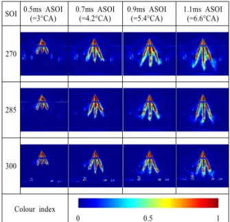
Fig. 5 Mie images during the compression stroke with swirl flow
SOI 0.5ms ASOI
(=3°CA) 0.7ms ASOI
(=4.2°CA) 0.9ms ASOI
(=5.4°CA) 1.1ms ASOI
(=6.6°CA)
270
285
300
Colour index
0 0.5 1
Fig. 6 Mie images during the compression stroke with tumble flow
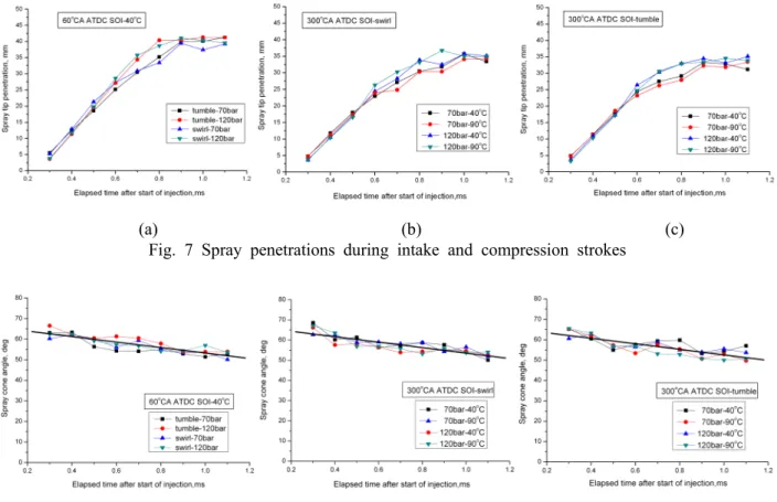
(a) (b) (c) Fig. 7 Spray penetrations during intake and compression strokes
Fig. 8 Spray cone angles during intake and compression strokes The most common technique to achieve mixture
stratification is by injecting the fuel during the compression stroke and after the closure of the inlet valve. In this study, three injection timings during the compression stroke have been selected 270°CA, 285°CA and 300°CA which were defined as medium and late injection timings. During this period, tumble motion was still existed but the swirl flow was decayed and at 300°CA, the turbulence intensity increased linearly across the cylinder while the weak main flow has moved towards the exhaust valve area. These tumbling/swirl velocity values are much smaller than those of early induction which may suggest that the injected spray pattern during the compression stroke can be less affected by the tumble motion.
Evolution spray pattern of start of injection at 270°CA, 285°CA and 300°CA after induction TDC, having the SCV fully closed (swirl), are displayed in Fig. 5. Not like the spray pattern of intake before, the axial and swirl mean velocities and
also the turbulence level were not so large to overcome the spray plumes momentum and therefore much less deformation and dispersion of fuel droplets. Till the elapsed time of 0.9ms ASOI, the spray plumes patterns were similar regardless of the SOI timing.
But, when the elapsed time goes over 0.9ms ASOI, the front shape of the tip of spray plumes can’t maintain its straight penetration and is distorted slightly perhaps due to RMS component of swirl flow. As start of injection timing retards, the growth of the spray penetration is restricted by the upward moving piston and higher chamber pressure. The spray penetration of 300°CA SOI was strongly affected and the shorter spray penetration can be observed than that of others.
The evolution of spray pattern under tumble flow condition is displayed in Fig. 6. Similar with the spray pattern under the swirl flow, the whole spray pattern was kept straight regardless of SOI.
As start of injection timing retards, growth of the spray plumes maintains its straight penetration
unlike that of the swirl flow.
3.3 Spray penetration and spray cone angle The spray penetration and spray cone angle of experiments results at different injection timing, injection pressure and coolant temperature at 1000 rpm are plotted in Fig. 7 and Fig. 8. The spray penetration of 60°CA SOI and Tcoolant= 40°C is shown in Fig. 7(a). The penetration is affected by fuel injection pressure so that at initial stage till 0.5ms ASOI, the spray penetration of 70bar is a little longer than those of 120bar this is mainly because the mechanical operational delay time of the injector at 120bar is longer.
But, the injected fuel droplets, possessed large momentum by the higher fuel pressure, and consequently penetrate more into the cylinder than the lower injection pressure as the time ASOI increases. From the elapsed time of 0.6ms ASOI, the spray penetration of 120bar becomes longer than that of 70bar. The penetration increases straight till 0.8ms ASOI and from 0.8ms ASOI, the penetration stops at about 40mm due to loss of droplets momentum.
The spray penetration of 300°CA SOI under swirl flow and tumble flow is respectively shown in Fig. 7(b) and Fig. 7(c). The spray penetration during compression stroke has similar trend to that of intake stroke. The penetration is also affected by fuel injection pressure. But additionally it is strongly affected by the chamber pressure (moving piston), which causes the maximum penetration of 35mm shorter than that of intake stroke. And after 0.9~1.0ms ASOI the spray tip starts to impinge on piston. So the injected fuel of the high pressure reaches on the piston earlier than that of the lower pressure.
Therefore it is required to carefully consider the extent of the fuel impingement according to spray penetration is small and not as noticeable as the fuel pressure. The plane (A-A) where the overall spray angle was calculated is shown in Fig. 2, and the angle was measured between the extreme edges of the two outer jet sprays near the injector tip where the effects of the cross-flow
was minimum.
Fig. 8 shows the spray cone angle during intake and compression stroke and at different injection pressures and coolant temperatures. The results showed that the overall spray angle remained constant and almost independent of injection pressure, chamber pressure and coolant temperature. And there is a small and gradual reduction in the overall spray cone angle with the elapsed time ASOI, which is similar for all conditions tested, so that making the overall spray cone angle smaller than that of the nominal value. This can be related to the complex flow structure inside the nozzle hole especially the presence of different types of cavitation8) depending on pressure difference across the nozzle due to the opening of the needle. In particular, there is a geometrical cavitation that forms on the upper part of the nozzle and can affect the trajectory of the exiting fuel jets by forcing them downwards.
4. Conclusion
Spray characteristics of a high pressure 6-hole multi-hole injector were investigated in an optical engine using Mie scattering. The results were obtained at an engine speed of 1000rpm and the effects of injection timing, in-cylinder charge motion, coolant temperature and injected fuel pressure were investigated. The most important findings are summarized below
1) To obtain a homogeneous and stoichiometric mixture, in-cylinder swirl has proved to be far more effective than the tumble flow during the intake stroke.The results showed a clear shift of the spray jets in the direction of the intake cross-flow.
2) The spray pattern of late injection during the compression stroke was little affected by tumble and swirl cross-flow. However, the effect of increased chamber pressure due to piston movement was considerable in limiting the spray jet penetration.
3) Fuel pressure promotes spray penetration although, during compression stroke, it is strongly affected by the upward moving piston causing an increase in the air density in the cylinder.
4) The overall spray cone angle was found to be constant and almost independent of injection pressure, chamber pressure and coolant temperature. A gradual reduction in the overall spray angle was also found with elapsed time after the start of injection, which could be related to the development of cavitation in the nozzle holes.
Acknowledgement
The authors wish to acknowledge Prof. C.
Arcoumanis, Dr. J. M. Nouri and Dr. Y. Yan who helped us proceed the experiments at The City University.
References
1. Fraidl, G. K., Piock, W. F., and Wirth, M., 1996, "Gasoline Direct Injection: actual trends and future strategies for injection and combustion systems", SAE 960465: pp. 95~111.
2. Wirth, M., Zimmermann, D., Friedfeldt, R., Caine, J., Schamel, A., Davies, M., Peirce, G.,Storch, A.,Ries-Müller, K., Gansert, K.P., Pilgram, G., Ortmann, R., Würfel, G. and Gerhardt, J., 2004, "A Cost Optimised Gasoline Spray Guided Direct Injection System for Improved Fuel Economy, Seminar on Fuel Economy and Engine Downsizing". Institution of Mechanical Engineers, One Birdcage Walk, London.
3. Preussner, C., Doring, Fehler, S., Kampmann, S., 1998, "GDI: Interaction between mixture preparation combution system, and injector performacne", SAE 980498.
4. Mitroglou N., Nouri, J. M., Yan Y., Gavaises M. and Arcoumanis, C., 2007, "Spray structure generated by multi-hole injectors for gasoline direct injection engines", SAE 2007-01-1417.
5. Mitroglou, N., Arcoumanis, C., Mori, K. and Motoyama, Y, 2005, "Mixture distribution in a multi-valve twin-spark ignition engine equipped with high-pressure multi-hole injectors", ICOLAD 2005, pp. 27~40.
6. Nouri J. M., Mitroglou, N., Yan Y. and Arcoumanis, C., 2007, "Internal flow and cavitation in a multi-hole injector for gasoline direct injection engines", SAE 2007-01-1405.
7. Karaiskos, I. E., 2005, "Spray structure and mixture distribution in a direct injection gasoline engine", PhD Thesis, University of London.
8. Nouri J. M., Mitroglou, N., Yan Y. and Arcoumanis, C., 2007, "Internal flow and cavitation in a multi-hole injector for gasoline direct injection engines", SAE 2007-01-1405.