Vol.21, No.4, (2019), pp.48~52 https://doi.org/10.9714/psac.2019.21.4.048
``
`
1. 서 론
고온 초전도 선재는 높은 임계온도, 적은 냉각 비용, 높은 운전전류와 같은 이점을 가지고 있어 [1], 고온 초전도 선재를 사용한 응용기기에 관한 많은 연구가 진행 중이다 [2, 3]. 그러나 기존 연구에 따르면 고온 초전도체 REBCO(Rare-Earth-Ba-Cu-O) 박막(film)과 벌크(bulk)는 외부 자기장 내에서 자기저항 및 홀 효과에 의한 전압이 측정된다 [4–12].
고자기장에 노출되는 고온 초전도 응용기기의 경우, 자기저항과 홀 효과에 의해 예측되지 않은 전압이 발생한다면, 초전도 응용기기의 퀜치(quench) 감지나 무절연 코일(no-insulation coil)에서 턴과 턴 사이에 흐르는 전류로 인한 자기장 균질도에 문제가 발생할 수 있다. 따라서 고온 초전도 선재를 이용하는 응용기기인 NMR/MRI 자석, 중이온 가속기의 사극자석 등에서 자석의 성능과 안정적인 운용을 위해 상용화된 고온 초전도 선재(high- temperature superconducting tape)의 자기저항 및 홀 효과에 관한 연구가 필요하다.
본 논문에서는 고자기장 응용기기에서 발생하는 알 수 없는 전압을 설명하기 위해 상용화된 REBCO 고온 초전도 선재의 홀 효과 및 자기저항 측정을 위한 실험을 진행하였다. 구리 전자석을 이용하여 초전도 선재에 자기장을 인가하는 장치를 제작하였고 액체질소 온도 (77 K) 조건에서 실험하였다.
자기저항 및 홀 효과는 구성하는 물질, 전하 수송자(charge carrier), 기하학적 구조 등에 따라 달라지기 때문에 희토류 원소가 다른 ㈜SuNAM의 GdBCO 기반 선재, ㈜AMSC의 YBCO 기반 선재를
비교하였다. 또한, 각 선재의 metal stabilizer 물질에 따른 자기저항 및 홀 효과에 의한 전압을 측정하였고, 측정된 전압을 통해 홀 계수와 자기 비저항을 계산하였고 분석하였다.
2. 자기저항 및 홀 효과 측정 실험
2.1. 이론
외부 자기장이 존재하는 공간에서 일반적인 도체에 전류가 흐를 때 전하 수송자에 로렌츠 힘(Lorentz force)이 발생한다. 그 결과 로렌츠 힘에 의해 전기장이 발생하는데 이 현상을 홀 효과(Hall effect)라 부르고 식 1과 같이 표현한다 [9].
𝐸⃗ 𝐻(𝐵) = −𝑅𝐻(𝐵)(𝐽 × 𝐵⃗ ) (1)
𝐸⃗ 𝐻 은 홀 효과로 인해 생성된 전기장을 의미하고 시료에 흐르는 전류 밀도 𝐽 에 자기장 𝐵⃗ 와 외적의 방향으로 작용한다. 𝑅𝐻 은 홀 계수(Hall coefficient)로 물질의 종류, 전하 수송자 등에 따라 다르다.
𝑉𝐻(𝐵) = ∫ 𝐸⃗ 𝐻(𝐵) ⋅ 𝑑 𝑙 (2)
식 2에서 𝑉𝐻 는 홀 전압(Hall voltage)을 의미한다.
𝑑 𝑙 은 홀 효과가 작용하는 미소 구간을 의미하고 본 실 험 에 서 는 전 압 탭 의 미 소 간 격 을 의 미 한 다 . 또한, 외부 자기장에 의해 전하 수송자(charge carrier)의 스핀 및 궤도 운동을 비롯한 복합적인 운동들로 인해 전류 방향과 나란하게 자기저항 효과라 부르는 저항 성분이 생성된다 [10, 13].
Hall voltage measurement with respect to internal layout of REBCO coated conductors in an external magnetic field
Young Gon Kima, Geonwoo Baeka, Seunghak Hana, Yojong Choia, Junseong Kima, Haeryong Jeonb, and Tae Kuk Koa,*
a Department of Electrical and Electronic Engineering, Yonsei University, Seoul, 03722, Korea
b Korea Basic Science Institute, Daejeon, 34133, Korea
(Received 8 October 2019; revised or reviewed 16 December 2019; accepted 17 December 2019)
Abstract
Recently, many studies have been reported on the magnetoresistance and Hall effect of REBCO thin films and bulk. The voltage interferes quench detection of high-temperature superconducting magnet and generates leakage current in no insulation high- temperature superconducting coil. Therefore, in this paper, experiments on magnetoresistance and Hall effect of commercial YBCO and GdBCO tapes have been carried out. As a result, anomalous voltages expected for the magnetoresistance and Hall effect of REBCO tapes were observed and analyzed. In addition, the voltage characteristics of REBCO have been identified, and the Hall coefficient are calculated for use in high magnetic field magnet applications.
Keywords: anomalous voltage, external magnetic field, Hall effect, magnetoresistivity effect, REBCO tape
* Corresponding author: [email protected]
Fig. 1. Illustration of how to measure the hall voltage using an external magnetic field.
Fig. 2. Internal alternating structure of stabilizer, metal, and REBCO layers in commercially available HTS tapes, (a) SuNam (GdBCO), (b) AMSC (YBCO).
외부 자기장에 의해 REBCO 박막과 벌크에 자기저항 및 홀 효과가 전압의 형태로 발생하는 것은 여러 논문에 의하여 밝혀졌다 [4–12]. 하지만 초전도 마그넷에 사용되는 REBCO 선재는 순수 초전도체가 아닌 substrate, 초전도체, silver, copper 등으로 구성되어 있기 때문에 벌크나 박막이 아닌 초전도 선재의 자기저항 및 홀 효과를 측정하는 실험이 필요하다.
2.2. 실험 환경
고온 초전도 선재의 자기저항 및 홀 효과 측정은 그림 1과 같이 외부 자기장이 선재 옆면인 y축에 입사하는 실험을 진행하였다. 고온 초전도 선재의 x축 방향으로 전류를 인가하면 외부 자기장에 의해 홀 전압은 선재의 z축 방향으로 발생한다. 따라서 홀 전압 측정을 위한 전압 탭은 그림 1과 같이 선재 z축 방향 양단에 위치한다. 또한, 그림 2와 같이 초전도 선재는 REBCO 층을 기준으로 증착 물질이 대칭적이지 않다. 따라서 REBCO 층에 가까운 면과 substrate 층에 가까운 면의 x축 방향 자기저항을 각각 측정하였다.
그림 2와 같이 1350 G에서 임계전류가 150 A 이상인 REBCO 선재를 사용하였다. 희토류 원소에 따른 차이를 확인하기 위하여, ㈜AMSC에서 제작된 4 mm YBCO 선재와 ㈜SuNAM에서 제작된 4 mm GdBCO 선재로 실험하였다. 또한, metal stabilizer 종류에 따른 특성을 비교하였고, copper나 SUS가 사용된 metal stabilizer에 따른 비교 실험을 진행하였다.
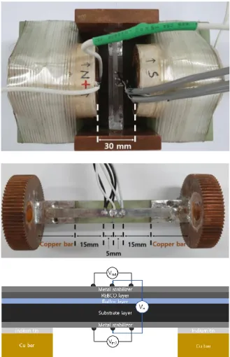
Fig. 3. (a) A picture combined REBCO tape and electromagnet for external magnetic field generation, (b) voltage tap location for REBCO tape magnetoresistance and Hall effect measurements. (c) the location of voltage taps for measuring magnetoresistance and Hall voltage.
상용화된 고온 초전도 선재의 자기저항 및 홀 효과 측정 실험을 위해 그림 3 (a)와 같이 초전도 선재 자기장 인가 장치를 제작하였다. 철심형 구리 전자석의 간격은 30 mm이고 중앙에 선재가 위치한다. DC 전류원을 이용하여 외부 자기장을 조절하였고 0 G부터 1350 G까지 0.84 G/s로 증가시켰다. 고온 초전도 선재의 전류는 연세대에서 연구 중인 공심형 고온 초전도 사극자석의 통전전류를 고려하여 50 A로 일정하게 유지하였다.
구리 터미널과 고온 초전도 선재의 substrate면을 인듐비스무트 합금으로 접합하였고, 그림 3 (b)와 같이 구리 터미널과 전압 탭은 15 mm 이상의 간격을 두었다. 홀 전압 측정을 위한 전압 탭은 선재 중심에 위치하고 자기저항 측정을 위한 전압 탭은 중심으로부터 5 mm 간격으로 양옆에 위치한다. 또한, 그림 3(c)와 같이 REBCO 층의 자기저항 전압 Vm1과 substrate 층의 자기저항 전압 Vm2 그리고 홀 전압 VH 측정을 위한 전압탭이 선재 윗면과 아랫면 그리고 중심에 위치한다. 전압 탭과 고온 초전도 선재는 접합의 용이성을 위해 인듐비스무트 합금보다 용융점이 높은 인듐주석 합금을 이용하여 접합하였다.
(a)
(b)
(c)
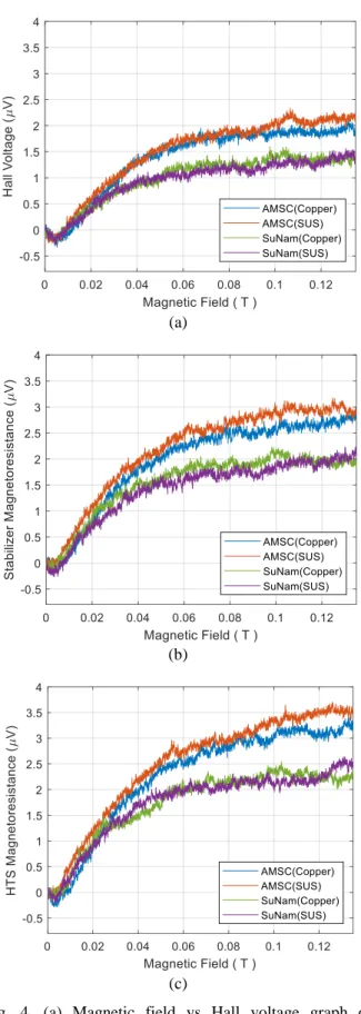
Fig. 4. (a) Magnetic field vs Hall voltage graph of commercialized REBCO tapes at 77 K. The voltage tap is located on the top and bottom of the REBCO tape.
(b) A graph of voltage varying with magnetic field due to magnetoresistance effect. The voltage taps are placed in the current direction at 10 mm intervals in the stabilizer layer.
(c) The voltage taps are located in the REBCO layer in the same manner as the method of measuring the magnetoresistance of the stabilizer layer.
Fig. 5. Hall coefficient of commercial HTS tapes at 77 K.
Hall coefficient is decreased in the magnetic field of 0.03 T or more. Hall coefficient is calculated by dividing Hall voltage by the magnetic field and the current.
3. 실험 결과 및 분석
3.1. 자기저항 및 홀 전압 측정 결과
그림 4 (a)는 전류 방향과 수직으로 발생하는 고온 초전도 선재의 윗면과 아랫면에서 측정된 홀 전압을 보여준다. 자기장이 증가함에 따라 모든 종류의 선재에서 홀 전압은 증가하는 경향을 보이고, YBCO 기반 초전도 선재의 홀 전압이 GdBCO 기반 초전도 선재의 홀 전압보다 크게 측정된다. 반면에 metal stabilizer에 따른 홀 전압의 차이는 거의 보이지 않는다. 또한, 0 T~0.01 T 자기장 범위에서 고온 초전도체의 특성인 음의 값을 가지는 홀 전압이 관측되었다. 그림 4 (b)는 전류 방향과 나란하게 발생하는 substrate 면의 자기저항에 의한 전압 그래프이다. AMSC 선재의 자기저항 효과가 SuNAM 선재에 비해 크게 측정되지만, metal stabilizer에 따른 차이는 거의 관측되지 않는다. 또한, 그림 4 (c)에서 보이듯 전류 방향과 나란하게 발생하는 REBCO 면의 자기저항에 의한 전압은 YBCO 선재가 GdBCO 선재보다 크게 측정된다. 모든 전압 측정 결과에서 metal stabilizer에 의한 영향은 거의 없는 것으로 보이지만, 자기저항 및 홀 효과에 의한 전압은 고온 초전도 선재의 희토류 원소에 따른 차이를 보인다.
3.2. 홀 계수 및 비저항
측정된 전압으로부터 식 1과 식 2를 이용하면 선재의 형상에서 홀 계수를 계산할 수 있다. 그림 5는 AMSC 선재와 SuNAM 선재의 계산된 홀 계수 RH를 보여준다. 홀 계수는 AMSC 선재가 SuNAM 선재보다 큰 경향을 보이고, 0.04 T 이상의 자기장에서 감소하는 경향을 보인다. 측정을 통해 구한 홀 계수는 식 1과 식 2를 이용하면 다양한 형상의 고온 초전도 응용기기에 적용하여 계산할 수 있다.
(a)
(b)
(c)
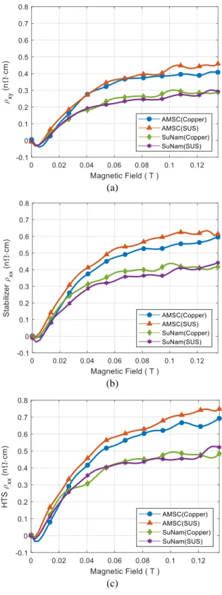
Fig. 6. (a) Hall resistivity, (b) magnetoresistivity of stabilizer layer and (c) HTS layer at 77 K.
그림 6 (a)는 전류가 x축으로 흐를 때 y축으로 발생하는 홀 비저항 𝜌𝑥𝑦 을 나타내는데 물질과 기하학적 구조에 따라 물성값이 다르다. 홀 비저항은 약한 자기장 (0~0.01 T) 내에서 음수로 측정되고 0.01 T 이상의 자기장에서는 세기에 따라 증가하는 경향을 보인다. 또한, YBCO 선재와 GdBCO 선재는 모두 약한 자기장 내에서 음의 값을 가지는 홀 비저항이 측정된다.
그림 6 (b)는 전류가 x축으로 흐를 때 x축 방향의 substrate 층에서 측정된 자기 비저항 𝜌𝑥𝑥 을 의미한다. 홀 전압과 다르게 모든 선재에서 유의미한 음의 비저항은 측정되지 않는다. 그림 6 (c)는 전류가 x축으로 흐를 때 x축 방향의 REBCO 층에서 측정된 자기 비저항 𝜌𝑥𝑥을 나타내고 자기장에 따라 가장 큰 증가 폭을 보인다. 선재별 자기장에 따른 전압과 같이 모든 비저항에서 metal stabilizer에 따른 차이를 보이지 않고, 일정 자기장 이상으로 증가함에 따라 측정된 모든 비저항은 증가하는 경향을 보인다.
REBCO의 변칙적인 음의 값을 가지는 홀 효과 (anomalous Hall effect)는 vortex와 super current의 상호작용으로 발생하는 것으로 추측된다 [14], [15]. YBCO와 GdBCO는 전하 운반자의 밀도, vortex의 엔트로피, 자화도 등의 물성이 다르므로 홀 전압 특성에서 차이가 발생한 것으로 보인다. 또한, 고온 초전도 선재에 흐르는 전류는 대부분 초전도 층에 흐르기 때문에 초전도체의 영향이 지배적이다.
따라서 동일한 초전도체에서 metal stabilizer에 흐르는 전류는 REBCO에 흐르는 전류보다 작기 때문에, metal stabilizer 간의 차이는 무시 가능할 크기로 측정된 것으로 보인다.
4. 결 론
기존 REBCO 박막과 벌크의 Tc 이하 액체질소 온도 77 K에서 외부 자기장에 의한 홀 효과와 자기저항에 관한 연구가 진행되었다. 본 논문에서는 REBCO를 사용한 상용화된 YBCO선재와 GdBCO 선재의 자기저항과 홀 효과에 의한 전압을 측정하였고, 측정된 자기저항과 홀 효과에 의한 전압은 외부 자기장에 따라 증가하는 경향을 보았다.
따라서, 고온 초전도 선재의 홀 효과는 REBCO를 사용한 고온 초전도 응용기기에 퀜치 검출에 영향을 줄 것으로 보인다. 하지만, 본 논문에서 인가된 최대 자기장은 1350 G로 다른 고온 초전도체의 연구들에 비해 작아서 고자기장 마그넷에 적용하기 위해서 추가적인 연구가 필요해 보인다. 또한, 고온 초전도체의 자기저항 및 홀 효과에 대해 이론적으로 확립되어 있지 않아 예측이 어렵지만, 선재의 홀 계수와 자기 비저항을 측정하여 홀 효과를 고려한다면, 기하학적으로 다른 여러 형태의 고온 초전도 응용기기의 원하지 않은 전압 연구에 활용할 수 있다고 사료된다.
ACKNOWLEDGMENT
This work was supported by “Human Resources Program in Energy Technology” of the Korea Institute of Energy Technology Evaluation and Planning (KETEP), granted financial resource from the Ministry of Trade, Industry & Energy, Republic of Korea, and by the National Research Foundation of Korea(NRF) grant funded by the Korea government(MSIP) (Nos. 20184030202270 and 2017R1A2B3012208)
REFERENCES
[1] S. R. Foltyn, L. Civale, J. L. MacManus-Driscoll, Q. X. Jia, B.
Maiorov, H. Wang, and M. Maley, “Materials science challenges for high-temperature superconducting wire,” Nature Materials, vol. 6, pp. 631-642, 2007.
[2] Drew W. Hazelton, Venkat Selvamanickam, Jason M. Duval, David C. Larbalestier, and William Denis Marki, "Recent Developments in 2G HTS Coil Technology," IEEE Transactions on Applied Superconductivity, vol. 19 , no. 3, pp. 2218-2222, 2009.
[3] Y. Wang and H. Song, “Influence of turn-to-turn resistivity and coil geometrical size on charging characteristics of no-electrical- insulation REBCO pancake coils,” Supercond. Sci. Technol., vol. 29, no. 7, pp.10-20, 2016.
[4] K. Maki, “Hall effect in dirty type 2 superconductors,” Phys. Rev.
Lett., vol. 23, no. 21, pp. 23–25, 1969.
[5] M. Galffy and E. Zirngiebl, “Hall-effect of bulk YBa2Cu3O7−δ,”
Solid State Commun., vol. 68, no. 10, pp. 929–933, 1988.
[6] T. T. Yasuhiro Iye and SHigeru Nakamura, “Hall effect in high temperature superconductors near Tc,” Physica C, vol. 159, pp.
616–624, 1989.
[7] S. J. Hagen, C. J. Lobb, R. L. Greene, M. G. Forrester, and J. H.
Kang, “Anomalous Hall effect in superconductors near their critical temperatures,” Phys. Rev. B, vol. 41, no. 16, pp. 11630–11633, 1990.
[8] S. J. Hagen, C. J. Lobb, and M. Eddy, “Flux-flow Hall effect in superconducting Tl2Ba2CaCu2O8 films,” Phys. Rev. B, vol. 43, no.
7, pp. 6246–6248, 1991.
[9] P. W. Eckels and J. H. Parker, “The Hall effect in superconductor stability,” Cryogenics (Guildf)., vol. 32, no. 5, pp. 490–493, 1992.
[10] H. D. Drew, “The ac Hall effect in high-Tc superconductors,” J.
Phys. Condens. Matter, vol. 8, no. 48, pp. 10037–10048, 1996.
[11] W. M. Woch, et al., “Magnetoresistance, Irreversibility Fields, and Critical Currents of Superconducting 2G Tape,” J. Supercond. Nov.
Magn., vol. 30, no. 3, pp. 569–574, 2017.
[12] P. Benetatos and M. C. Marchetti, “Plasticity in current-driven vortex lattices,” Phys. Rev. B - Condens. Matter Mater. Phys., vol.
65, no. 13, pp. 1–10, 2002.
[13] R. S. W. Go¨b and W. Lang, “Magnetoresistance of a YBa2Cu3O7 Corbino disk: Probing geometrical contributions to the unconventional normal-state magnetoresistance of high-temperature superconductors,” Phys. Rev. B, vol. 57, no. 14, pp. 191–194, 1998.
[14] D. I. Khomskii and A. Freimuth, “Charged vortices in high temperature superconductors,” Phys. Rev. Lett., vol. 75, no. 7, pp.
1384–1386, 1995.
[15] A. T. Dorsey, “Vortex motion and the Hall effect in type-II superconductors: A time-dependent Ginzburg-Landau theory approach,” Phys. Rev. B, vol. 46, no. 13, pp. 8376–8392, 1992.