Feasibility Study on the LTOP Accident during Low Power & Shutdown Period
Ho-Gon Lim, Jin-Hee Park, Seung-Cheol Jang, Jae-Joo Ha
Korea Atomic Energy Research Institute, Integrated Safety Assessment Div., 150 Dukjin-dong, Yuseung-gu, Daejeon 305-353, Korea [email protected]
1. Introduction
The low temperature over-pressure (LTOP) accident can be caused by an over-charging of the RCS (mass inflow) or a loss of the shutdown cooling of the RCS (energy inflow) during this period of Korean nuclear power plant (NPP) of Combustion Engineering (CE) design [1,2].
If the LTOP prevention valves fail to close after the release of the RCS water, it will be an initiator of the loss of coolant accident (LOCA). Also, when the LTOP prevention valves fail to open, the RCS pressure will further increase to reach the set-point of the pressurizer safety valve (PSV). Since the shutdown cooling system (SCS) is installed and being operated at these accident situations, the subsequent pressure increase after the LTOP prevention valve failure will cause a SCS pipe line rupture because the design pressure of the SCS pipe line is low when compared to the PSV set-pressure. This accident scenario may be an initiator of the interfacing system loss of coolant accident (ISLOCA).
In the present study, we simulated these LTOP accidents using the thermal-hydraulic reactor safety analysis code, MARS [3]. Based on the simulated results, we also developed the event trees of these accidents.
2. T/H Analysis for LTOP Accident
As an initiator of the initiating event in the LP/SD, the LTOP accident should be analyzed properly according to their accident sequences.
The first and second solid operations are classified as a part of the plant operating state (POS) 3 and 12 of the LP/SD PSA respectively. Since the POS 3 is more severe than the POS 3, the simulation in the POS 3 is only addressed in this paper. A detailed description of each solid operation and the T/H analysis are given below
2.1 POS 3
Two types of LTOP accident are considered during this period, mass inflow by an over-charging of the RCS and an energy inflow by a loss of the shutdown cooling system (LOSCS). Each accident is analyzed below.
The boundary conditions for the simulation are given in Table 1[4].
Table 1 Initial & Boundary Conditions of POS 3
RCS pressure 2.75 MPa
RCS temperature 419.15 oK
LTOP valve A open set pressure 3.58 MPa LTOP valve A close set pressure 3.23 MPa LTOP valve diameter 0.1524 m (6 inch) PSV open set pressure 17.2 MPa
PSV close pressure 14.1 MPa
PSV diameter 0.089 m (3.5 inch)
Mass inflow
Two accident sequences were simulated, the case of an available LTOP prevention valves and that of the LTOP prevention valve’s failure. Fig. 2 shows the simulation results 0 400 800 1200 1600 2000 0 5 10 15 20 RC S Pr e ss u re (M pa ) Time(sec) LTOP valve available LTOP valve unavailable LTOP valve set-pressure
PSV set-pressure
Fig. 1. The behavior of the RCS pressure for a LTOP accident by a mass inflow in the POS 3 Energy inflow
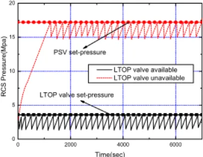
The simulation is performed with the same nodalization used in the mass inflow scenario. As in the mass inflow case, two accident sequences are simulated, the case of a LTOP prevention valve available and that of a LTOP prevention valve failure. Fig. 2 shows the simulation results. 0 2000 4000 6000 0 5 10 15 20 R C S Pres su re(M pa) Time(sec)
LTOP valve available LTOP valve unavailable LTOP valve set-pressure
PSV set-pressure
Fig. 2. The behavior of the RCS pressure at LTOP accident by energy inflow in the POS 3 3. EVENT TREE CONSTRUCTION
Transactions of the Korean Nuclear Society Autumn Meeting Busan, Korea, October 27-28, 2005
The accident sequences analysis for the POS 3 LTOP accident was performed for a mass and an energy inflow.
Mass inflow
Fig. 6 shows the event tree for the LTOP accident by the mass inflow.
Mass inflow Flow control Valve status RCS status success O.K
Stuck close To ISLOCA
fail
Stuck open To MBLOCA
Fig. 3. Event tree for the LTOP accident by mass inflow in the POS 3
The frequency of each initiator in Fig. 3 can be quantified using the following equation.
SO CC LTOP LOCA
f
P
P
f
=
M•
•
(1) SC CC LTOP ISLOCAf
P
P
f
=
M•
•
(2) WherefLOCA : LOCA frequency
fISLOCA : ISLOCA frequency
fLTOPm : Frequency of LTOP by mass inflow
PCC : Probability for the operator not to control
charging flow
PSO : Probability of LTOP valve stuck open
PSO : Probability of LTOP valve stuck close
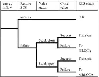
Energy inflow
Fig. 4 shows the event tree for the LTOP accident by an energy inflow. energy inflow Restore SCS Valve status Close valve RCS status success O.K Success Transient Stuck close failure Failure To Success ISLOCA Transient Stuck open Failure To MBLOCA
Fig. 4. Event tree for the LTOP accident by energy inflow in the POS 3
The frequency of each initiator in Fig. 4 can be quantified using the following Boolean equation.
SV SO SCS LTOP LOCA
f
P
P
P
f
=
E•
•
•
(3) SV SC SCS LTOP ISLOCAf
P
P
P
f
=
E•
•
•
(4) WherefLOCA : LOCA frequency
fISLOCA : ISLOCA frequency
fLTOPm : Frequency of LTOP by energy inflow
PSCS : Probability for the operator not to restore the SCS
or operate redundant SCS
PSO : Probability of LTOP valve stuck open
PSC : Probability of LTOP valve stuck close
PSV : Probability for the operator to close the SCS
suction
4. CONCLUSIONS
The present study addressed a LTOP accident progression according to the causes of the accident in the POS 3. It was anticipated that the LTOP accident in the POS 12 is relatively resistible for the LTOP accident while the one in the POS 3 can be an initiator for a LOCA and an ISLOCA. Based on the results of the T/H analysis, an event tree was also developed for the POS 3.
A subsequent numerical quantification should be addressed by assigning a specified value for the valves and the operator actions. Also, the effects of a LTOP accident during the dynamic ventilation of the POS 12 should be analyzed.
ACKNOWLEDGMENTS
This work was performed under the Long-term Nuclear R&D Program sponsored by the Ministry of Science and Technology.
REFERENCES
[1] Korea Electric Power Corporation, “Korea Standard
Nuclear Power Plant Safety Analysis Report”,
[2] KHNP, “Yong-Gwang Second Nuclear Power Plant
Operation Manual”, Vol. 2 1995
[3] Jeong, J. -J., Ha, K. S., Chung, B. D., Lee, W. J.,
“ Development of A Multi-dimensional Thermal-Hydraulic
System Code, MARS 1.3.1,” Annals of Nuclear Energy
26(18), 1161-1642, 1999
[4] Young-Seok Son, Jee-Young Shin, Ho-Gon Lim, Jin-Hee Park and Seung-Cheol Jang, “Thermal-hydraulic calculations using MARS code applied to low power and shutdown probabilistic safety assessment in a PWR”, Nuclear Engineering and Design, Volume 235, Pages 1571-1581, 2005