Contents lists available atScienceDirect
Nuclear Materials and Energy
journal homepage:www.elsevier.com/locate/nmeModelling of the effect of ELMs on fuel retention at the bulk W divertor of
JET
K. Heinola
⁎,a,b, T. Ahlgren
a, S. Brezinsek
c, T. Vuoriheimo
a, S. Wiesen
c, JET Contributors
1 aDepartment of Physics, University of Helsinki, P.O. Box 64, Helsinki 00560, FinlandbInternational Atomic Energy Agency IAEA, Vienna A-1400, Austria cForschungszentrum Jülich GmbH, Jülich D-52425, Germany
A R T I C L E I N F O Keywords: ELM Fuel retention Multi-scale computing JET A B S T R A C T
Effect of ELMs on fuel retention at the bulk W target of JET ITER-Like Wall was studied with multi-scale cal-culations. Plasma input parameters were taken from ELMy H-mode plasma experiment. The energetic intra-ELM fuel particles get implanted and create near-surface defects up to depths of few tens of nm, which act as the main fuel trapping sites during ELMs. Clustering of implantation-induced vacancies were found to take place. The incoming flux of inter-ELM plasma particles increases the different filling levels of trapped fuel in defects. The temperature increase of the W target during the pulse increases the fuel detrapping rate. The inter-ELM fuel particle flux refills the partially emptied trapping sites and fills new sites. This leads to a competing effect on the retention and release rates of the implanted particles. At high temperatures the main retention appeared in larger vacancy clusters due to increased clustering rate.
1. Introduction
The JET tokamak with its ITER-Like Wall (ILW) project[1]provides a unique opportunity to study the plasma-material interactions (PMI), such as transient heat loads, erosion, melting and melt layer motion, deposition, global material migration, and fuel retention taking place in operating the next-step fusion device ITER. Efforts for a comprehensive PMI model is an ongoing and actively studied topic with ILW. The ILW plasma-facing components (PFCs) comprise of main chamber limiters made of bulk beryllium (Be) and of divertor armour tiles either made of bulk tungsten (W), or W-coated carbon-fibre composite (CFC) tiles. The understanding and control of the PMIs, such as short-term[2]and long-term[3,4]fuel retention, and migration and deposition of the eroded wall material[4–9]are of vital importance for economical operation of a future fusion reactor.
The post-mortem analyses of the JET-ILW PFCs retrieved from the JET vessel after the first operational ILW campaign 2011–2012 mapped the global distribution of the deposits and fuel retention inside the machine ([3,5–7,10,11] and references therein). The global fuel re-tention rate was found to have decreased in JET-ILW by a factor > 18 as compared to operations with the previously installed all-carbon wall of JET (JET-C) [3]. Gas balance measurements performed during the first ILW campaign have shown a factor 10–20 reduction in the
long-term fuel retention measurements as compared to JET-C[2]. A more detailed experimental study on the local fuel recycling at the JET-ILW plasma strike points showed the evolution and dynamics of near-surface retention, implantation, outgassing and retention of fuel on W being affected by the surface temperature evolution during the plasma loading[12]. In that work, using subsequent plasma discharge series for steady-state plasmas in L-mode the W target temperature was observed to increase from 65∘C up to ∼ 350∘C owing to power deposition during
plasma discharges (duration ∼ 20 s) and only inertial cooling between subsequent discharges ( ∼ 20 min between pulses). This temperature change resulted in decrease of the short-term fuel retention in W di-vertor by 1/3 during the subsequent pulses. The effect of fast time-scale events on fuel retention in ILW W was studied with a series of identical H-mode plasmas with edge-localized modes (ELMs)[12]. The intra-ELM loads increase the particle and heat loads on the W target, and it was shown the ELM-induced temperature increase on the deposit-free bulk W target to exceed 1400∘C at the end of the pulse.
Present work scrutinizes the ELM-induced effects on W target computationally with the concept of sequential multi-scale calculations. Objective is in the local fuel retention by studying computationally the bulk W divertor target properties during H-mode plasmas with type I ELMs. The method used solves numerically a set of rate theory equa-tions (RE) describing the dynamics of the ELM-induced events and fuel
https://doi.org/10.1016/j.nme.2019.03.013
Received 31 July 2018; Received in revised form 9 February 2019; Accepted 15 March 2019
⁎Corresponding author.
E-mail address:[email protected](K. Heinola).
1See the author list of X. Litaudon et al. Nucl. Fusion 57, 102001 (2017).
Available online 29 March 2019
2352-1791/ © 2019 The Authors. Published by Elsevier Ltd. This is an open access article under the CC BY-NC-ND license (http://creativecommons.org/licenses/BY-NC-ND/4.0/).
retention occuring in the bulk and on the target surface [13,14]. Equations are parametrised with first-principles calculations using electron density functional theories (DFT), with molecular dynamics (MD) simulations, and with binary collision approximation (BCA) cal-culations. The length and time scales in the present methodology can vary from Å to meters, and from femtoseconds to minutes, respectively. The limitation of the present RE method [13]is that the monitored concentrations (e.g. plasma particles, defects) are presented one-di-mensionally as a function of depth. As an advantage, there is no lim-itation in the number of particles and other monitored entities, the modelled time and length scales can be extended to macroscopic scales, and the simulations can be executed with low computational cost. Thus, the RE method applied[13]is presently the only computational ap-proach suitable for simulating ELM-induced fuel retention, ELM-in-duced defect dynamics and evolution on a fusion plasma-pulse scale by including the real physical processes taking place in the bulk of the target.
2. Methodologies
2.1. Fusion plasma experiment
Fuel recycling and dynamics at the W divertor target of JET-ILW has been studied with dedicated H-mode plasma experiments with type I ELMs in Ref.[12]. It was found that the resulted fuel content in the W target depends on the fuel particle impact energy and on the flux of the particles. Moreover, the dynamics is largely influenced by the tem-perature evolution of the target. In JET-ILW there is no active cooling of the PFCs, which results in large variation in the target temperature during plasma operations. The complex interplay of fuel retention, re-cycling, implantation, and outgassing can be investigated with various diagnostics of JET-ILW[15–18]via assessing the temperature evolution of the target, and the plasma particle fluxes, recycling, and impact energies at the target. The experiment comprised of 351 identical di-verted ELMy H-mode pulses (JET pulse numbers (JPNs) 83623–83974 with auxiliary heating 11 MW and gas injection 1022D s 1), with the
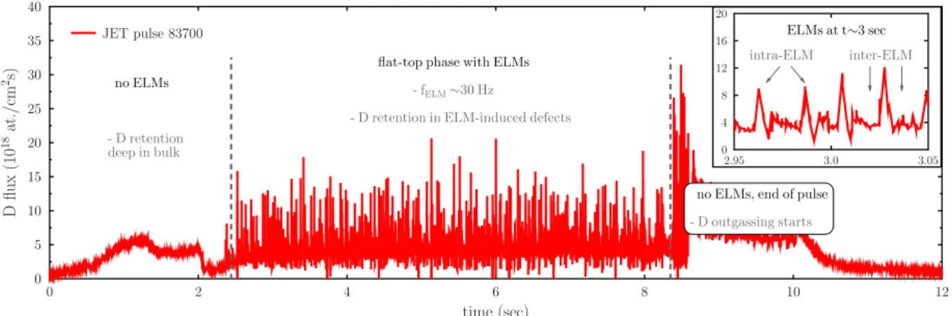
inner strike point on tile 3 (W-coated CFC) and the outer strike point (OSP) on tile 5 (bulk W). Pulse JPN83700 was chosen as a reference pulse for present work (Fig. 1).
An extensive analysis on the properties of the ELMs carried out in Ref.[12]showed the averaged D flux and energy to be ∼ 3.1 × 10¹⁹
cm 2s 1 and ∼ 3 keV during an ELM (intra-ELM), respectively, and
∼ 1 × 1019 cm 2s 1 and 200 eV in-between ELMs (inter-ELM). The
ELMs appeared on the flat-top phase of the pulse with a frequency fELM≈ 30 Hz (Fig. 1). The duration of the ELM footprint, characterized
by the heat load pattern, on the W target is ∼ 6 ms with a sharp rise of
the D flux for 2 ms followed by a flux decay for 2 ms < t < 6 ms[12]. Integrating over the averaged ELM D flux profile one gets a D im-plantation dose of (1.3 ± 0.3) × 1016cm 2per single ELM. For
com-parison, using fELM≈ 30 Hz an estimated inter-ELM period of ∼ 27 ms
results to a D implantation dose ∼ 2.7 × 1017cm 2between ELMs. A
part of the energetic 3 keV intra-ELM dose gets backscattered from the target surface due to the high mass difference between the projectile (D) and the target (W) atoms, but the majority gets implanted in the target, and may create implantation-induced - or ELM-induced - defects in the bulk, such as mono-vacancies (V1) and self-interstitials (I1)[13].
The ELM-implanted D diffuses from the implantation zone, or gets trapped to any of the defects in the bulk (ELM-induced defects, intrinsic defects and impurities, grain boundaries, etc). The out-diffused D can be seen as outgassing and desorption. Once the target temperature gets elevated during the pulse and subsequent ELMs, the thermodynamic energy stored in the target increases the energy levels of the trapped particles inducing D release, which is seen as out-diffusion and fuel recycling at the target. In Ref.[19]it was noted the W target plate of JET-ILW representing an additional fuel particle sink for a few ms, which can be defined as required refill-time after an ELM crash. Un-derstanding all these events taking place in the bulk of the target, re-quires examination at the atomic level. Hence, applying a modern multi-scale computational method provides atomistic level insight to the ELM-scale fuel retention events, and further, the same methodoly can be extended covering all the ELM events taking place throughout the corresponding plasma pulse. In this work, the effect of ELMy H-mode plasma on D fuel retention on W target has been examined by using real experimental ILW plasma pulse data at the target as input for computations to study the trapping, release and recycling phenomena of fuel particles. In the following section, the computational metho-dology applied in this work is described and the formulation is given. 2.2. Computational method and simulation setup
The RE simulation method used is based on solving a set of rate theory equations describing all the physical and chemical processes in the target material. These include D plasma particle implantation, im-plantation-induced defect creation, diffusion of the plasma particles and defects, trapping to defects and to impurities carbon (C) and oxygen (O), release from and retrapping to defects and impurities, diffusion of plasma particles and defects, and clustering and dissociation of defects or particle-defect systems. The present RE method has been described in depth in Refs.[13,14]and in the following only the main features are summarized. The concentration C for each examined distinct system, or entity - as function of depth and time - is given by the following coupled partial differential equations[20–22]:
Fig. 1. The JET-ILW ELMy H-mode plasma pulse used in the RE calculations. D flux is measured with a Langmuir probe at the outer strike point on bulk W target
= + ± ± = = C X t t D C x t x S x t k D C x t C x t ( , ) ( , ) ( , ) ( , ) exp ( , ), N N 2 2 , 1 2, 1 EA kT, (1)
where α, β, γ and δ stand for hydrogen, vacancy (V), self-interstitial atom (I), impurities (here C and O), and combinations of all of them. In total there are N distinct entitites, which are monitored simultaneously. The first term on the right-hand side ofEq. (1)is the diffusion of an entity α with a diffusion constant Dα. The second term Sαis the source,
such as intra-ELM implantation of D and the corresponding creation of implantation-induced defects. Third term describes all the exothermic events, such as trapping of D and clustering of defects, with a corre-sponding sink strength,k2,. The last term is for endothermic processes,
such as detrapping of D and dissociation processes of defects described with a pre-exponential factor νδ, and an activation energy EA,δneeded
for the system δ to break up. DFT calculations were used in determining the fundamental properties of W, such as the bulk, surface, and the point defect properties of mono- and di-vacancies (V1 and V2), and
interstitials (I1)[23–26]. Further, DFT was used to determine the
hy-drogen properties in W - diffusion ( =D0 4.8×10⁸m2/s andEm=0.26 eV)[25], and binding energies (Eb) to vacancies[24,27], and to C and O
impurities (1.25 eV and 1.19 eV, respectively) [14]. An assessment using the difference in the zero-point energies (ΔZPE) was applied for determining the energy needed for D to detrap from a defect as
= + +
Et Eb Em ZPE(more details in Ref.[14]).
As described inSection 2.1, the simulation input parameters for the source term S were real ELMy H-mode plasma parameters at the OSP on the bulk W outer target plate of the ILW divertor. The D flux data as measured with a Langmuir probe on bulk W divertor tile 5, stack C, were taken as is without reducing the number of particles. The D impact energies were varied between the reported [12]averaged inter-ELM energy (200 eV/D) and the intra-ELM energy (3 keV/D). The resulted profiles for D implantation and the implantation-induced defects, and the subsequent collision cascades were calculated with BCA[28]and MD[23,29], respectively. The surface temperature evolution was cal-culated with the heat flux obtained from Langmuir probe measured D flux (Fig. 2) by numerically solving the one-dimensional heat diffusion throughout the bulk W target. The inter-ELM impact energy is not sufficient for creating any lattice damage due to the high displacement energy of W (90 eV[30]). Also, the low inter-ELM implantation dose (Section 2.1) together with the increasing sample temperature does not create local defects due to hydrogen supersaturation, such as blistering [31]. In the present calculations, all the lattice defects were created during intra-ELM impacts. The evolution of the ELM-induced defects
(V1, I1) was monitored in the simulations, and clustering of V1s up to
V2Di( = …i 1 6) was included.
Hydrogen traps easily to impurities in metals, which is often ne-glected in time-dependent simulations. The main impurity, excluding molybdenum, in a bulk W sample is C with concentration of ∼ 10 µg/g (typical high purity 99.99% polycrystalline W by Plansee AG), corre-sponding to about 1025C at./m3. From this value a constant C
con-centration of 5 × 1018 cm 3was chosen to be used in these
calcula-tions. Similarly, using real impurity values for O in W, a constant concentration of 2 × 1018cm 3 was taken as O impurity level in the
bulk W.
An earlier study on D retention (implantations with 1.5 keV/D and 6.4 × 1014cm 2s 1) in single-crystalline W and in four different types
of polycrystalline W showed 50% of the implanted D being retained in each W type similarly far beyond the implantation zone in unspecified lattice imperfections[32]. A later study with similar findings in single-crystalline W suggested these imperfections to be mostly intrinsic im-purities[33]. Our earlier extensive RE simulations of experimental D implantations in polycrystalline W concluded that the typical number of intrinsic grain boundaries cannot exclusively explain the observed long range retention, but the intrinsic number of impurities, such as C and O, must play a role in the long-range trapping[13]. In the present work, the RE calculations study D retention covering the ELM-induced near-surface implantation zone and the long-range region in the bulk. In addition to the aforementioned D trapping to point defects, trapping to intrinsic impurities are included but the effect of grain boundary trapping remains as part of a future work. That work comprises of D trapping to and diffusion along the grain boundaries in W. However, more DFT data is required for simulating reliably the effect of grain boundaries to D retention in W with RE. Further, clustering of vacancies to V3, V4,…will most likely play an important role in D retention in the
implantation-damaged zone of W. The effect of vacancy clustering to hydrogen trapping during ELMs will also be included in the future work.
3. Results
The D flux to the OSP (Fig. 1) shows two distinctive phases, or re-gions of the pulse. The time interval 0 < t < 2.4 s, which has no ELMs, and the subsequent flat-top phase lasting for 6 s with ELMs. Further, the flat-top phase can be divided to intra-ELM and inter-ELM phases. During the plasma phase without ELMs, the impact energy of the in-coming D is 200 eV per ion, which is high enough allowing the particles the penetrate the surface (if not backscattered), but not enough for creating any additional lattice damage in the bulk. However, the RE simulations show that the penetrated D particles do not stop in the bulk, but diffuse rapidly back to surface, or deeper in the bulk where they get trapped to the impurities C and O. After the first second of plasma exposure this trapped D profile is at depth > 3μm, and reaches 7 µm at 2.4 s. The amount of free D on solute sites at 2.4 s is highest near the target surface ∼ 7 × 1016 cm 3, and the free D profile shows a
de-caying tail towards the bulk and goes to zero at < 6µm.
The plasma flat-top phase including ELMs takes place after 2.4 s. The intra-ELM impact energy reaches 3 keV/D whereas the inter-ELM impact energies remain an order of magnitude lower at 200 eV/D. The intra-ELM energy is sufficient for creating implantation-induced da-mage in the target. In the RE calculations the defects created are the primary defects V1and I1, which were allowed to diffuse and trap D. As
was calculated inSection 2.1a single ELM of duration ∼ 6 ms on the average transports (1.3 ± 0.3) × 1016cm 2of D to the target. An
ex-ample on the effect of this dose in the bulk is visualized inFig. 3. The ELM creates approx. 1011cm 2new V
1’s instantaneously to
near-sur-face region with a concentration profile maximum at a depth ∼ 10 nm. These defects get gradually filled during the first 2 ms by the incoming D. Also, the number of already existing V1’s with different filling levels
of D (V1Di; = …i 1 6), can be seen to increase during the ELM. By the end Fig. 2. Target temperature evolution as calculated from the D flux to the W
target. At time > 2.4 s the temperature increases gradually, and the ELMs in-duce a pulsed increase to the temperature with ΔT ∼ 100 K reaching tem-peratures ≳ 1400 K in the end of the pulse.
of the ELM (2 ms < t < 6 ms) as the incoming D flux decreases from its maximum value back to its background inter-ELM level and the tem-perature is increased due to heat absorbtion, the detrapping of D from V1Di’s takes place which is seen as a decrease in the D population of
V1’s. However, this detrapping flux is quickly balanced by the incoming
inter-ELM flux of D, and the detrapping-retrapping processes appear to find an equilibrium during the inter-ELM phase. The time required for finding an equilibrium is 4 5 ms, which corresponds to the reported experimental refill-time at the OSP of JET-ILW[19]. As a result, the post-ELM retention in the target is higher by ∼ 1014D cm 2compared
to the pre-ELM retention. This corresponds to < 1% of D retention per an averaged ELM. The complex intra-ELM filling and populating defects with D followed by emptying-filling processes during the inter-ELM phase takes place in the subsequent ELMs until the end of the pulse. A snapshot of the flat-top phase with longer timescale including multiple ELMs is shown in Fig. 4. Each ELM creates new vacancies which eventually increase the amount of retained D in the target by popu-lating V1’s with different filling levels of D. It is important to note, that
during the pulse the target temperature increases, which increases the D release rate from the defects, but which in turn competes with the re-trapping rate and with the amount of new D coming from the plasma into the bulk. Moreover, since the defects considered in this work trap the D in low numbers (retention < 1%), the flux of free D back to the target surface shows no delay as compared to the incoming D flux. The experimentally observed ∼ 8 ms delayed secondary D peak related to local recycling at the target[12]remains missing in the current RE simulations. Future work comprises of ELM studies with clustering of vacancies, which may play a role in the experimentally observed de-layed D recycling phenomena.
As the temperature keeps increasing the free V1become mobile and
the clustering to V2 takes place as V1+V D1 i V D2 i and
+ + i
V1 V1 V2 D V D2 i with = …i 1 6. Clustering of V’s further into larger clusters (V , V ,3 4 …) are part of a future work.Fig. 5shows the formation and evolution of V1Di’s and V2Di’s during the full pulse. Also
is shown the evolution of D trapped to impurities C and O. The for-mation of V1’s and V2’s filled with different levels of D starts to take
place as a direct influence of the ELMs. The number of V1’s and V2’s
increase during the flat-top phase until the target temperature reaches level, where the diffusion of V1overrides the filling of V1with D. This
Fig. 3. An example on the dynamics of vacancy creation, and trapping and
release of D from vacancies during a single ELM at 3.6 s < t < 3.64 s of the plasma pulse (ELM duration ∼ 6 ms). This ELM results in target surface max-imum temperature TELMmax 834K and ΔT ∼ 100 K. Top: The ELM creates ∼ 1011 cm 2new mono-vacancies (V
1), which together with the existing V1are filled
with the incoming D particles. Beyond the ELM peak (> 6 7 ms) the filling levels of V1Dientities ( = …i 1 6) get stabilized, and there are no empty V1left.
Bottom: Evolution of all the D-filled V1during a single ELM. The total amount
of V1Dientities ( = …i 1 6) after this ELM is ∼ 1014cm 2(see text for details). The subfigure shows the ranges of ELM-implanted D with 3 keV, and the re-sulted defect (V1, I1) distributions.
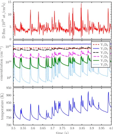
Fig. 4. Example on the effect of multiple ELMs to bulk W target (time interval
3.5 s < t < 4.0 s). Top: Incoming D flux as measured with Langmuir probes at the OSP. Centre: Dynamics of the V1filling levels due to retention, trapping and
retrapping of D. Bottom: Temperature evolution at the OSP.
Fig. 5. Effect of ELMs on the evolution of D trapping in and release from small
vacancies (V1and V2). Also shown the effect of C and O impurities to D
trap-ping. As the temperature increases, the formation of V2s takes place as the V1s
and V1s with D cluster. After the pulse only a fraction of D is retained in the V1
can be seen at ∼ 900 K (t ∼ 4.5 s) as a sudden increase in the formation of V2accompanied with a corresponding decrease in the number of V1.
This is a result of dynamical interplay between the creation of new V1’s,
D filling vacancies, and V1’s becoming increasingly mobile resulting in
abundance of V2’s. However, as the target temperature increases even
further to ∼ 1100 K (t ∼ 6 s), the D detrapping rate from V2propagates
leaving more unfilled V2behind, which in turn face prompt dissociation
at high temperatures[26]. In the end of the pulse there is only a small fraction of D left in vacancies, whereas the majority of the retained D is trapped to the impurities C and O (Fig. 5). These concentration profiles of D trapped to C and O extend to several µm’s deep. A similar trapping profile is expected to be at the grain boundaries extending throughout the bulk [13]. A more detailed grain boundary trapping study is in-cluded in a future work. To summarize, the ELM-induced dynamical D retention and release events take place in the near-surface region of few tens of nm’s, whereas the long-range and long-term D trapping extends deep in the bulk. This long-range trapping profile has been also ob-served experimentally in the post-mortem analyses (see e.g. Ref.[4] and references therein), which might be a combination of trapping to impurities, grain boundaries and other intrinsic long-range defects. However, the present calculations do not show the experimentally ob-served near-surface D concentration to remain after the pulse. Further calculations are required, and it may be that the near-surface D con-centration originates from the ELM-induced effects where the trapped D is in large-sized vacancy-like clusters (V3, V4, ...). Computational
stu-dies of ELM-induced defects including larger vacancy cluster sizes with hydrogen trapping properties are part of a future work.
4. Summary and conclusions
To summarize, plasma fuel retention at bulk W target during an ELMy H-mode pulse of JET-ILW has been studied computationally with multi-scale RE calculations. Real plasma parameters at the target, such as the D flux and impact energies, were used as input from a series of ELMy H-mode plasma experiments. D retention, diffusion, detrapping and retrapping, ELM-induced defect creation, and intrinsic impurities in W were included in the calculations. Due to inertial cooling of JET-ILW the resulted temperature evolution plays a critical role in fuel retention and in the ELM-induced defect evolution. During an ELM, a complex interplay takes place between the defects created and the retention, detrapping and retrapping of the incoming fuel partiles. An averaged D implantation dose per ELM is (1.3 ± 0.3) × 1016cm 2,which creates
approximately 1011cm 2 vacancies in the target. However, these
va-cancies get occupied with different filling levels of D in the ELM time scale. Further, as the temperature increases during the ELM, the for-mation of larger vacancy clusters, i.e. di-vacancies, takes place via mobilization and clustering of the mono-vacancies. The number of larger vacancy clusters and the amount of D trapped in the clusters increase during the pulse as the target temperature rises. At ≳ 900 K the number of D-filled V1starts to vanish, whereas the formation of larger
vacancy systems as D-filled V2keeps on increasing. This is the result of
ELM-induced V1becoming highly mobile in ELM timescales due to the
high target temperature. It has been shown in Ref.[26]the V2in W
having similar diffusion properties as the V1, and that the dissociation
probability of a V2increases exponentially with temperature. As a result
of these properties, at temperatures ≳ 1100 K the amount of D-filled V2
starts to decrease rapidly. The high temperature prevents the formation of new V2D systems, since the diffusion of the ELM-induced vacancies
becomes greater than the lifetime of the V2 clusters. It is worth to
highlight, the present work does not assess the formation of even larger vacancy clusters of V3, V4, .... It has been shown in Ref.[13]the
for-mation large-sized W vacancy clusters to take place in the near-surface region of couple of tens of nm during an ELM-relevant D implantation with few keV’s in W. Further, in Refs.[23,26]it was shown the large-sized vacancy clusters in W to be increasingly stable as the cluster size increases. Therefore, formation of large-sized vacancy clusters in W
may take place during ELMs, and which can survive the high heats absorbed in the target during ELMy pulses. Moreover, it is likely that these large-sized vacancy clusters trap fuel particles efficiently. The inner surfaces of the vacancy-type defects represent a surface-like trapping site for fuel particles. Thus, the high energy required for D surface-to-bulk motion in W[24]prevents the D of detrapping from large-sized vacancy-type defects even at very high temperatures. The effect of W main impurities C and O was seen to play a crucial role in D trapping and cannot be neglected. Even the typical levels of impurity concentrations may retain fuel particles at very high target tempera-tures. This is due to the impurity concentration profiles extending throughout the target providing a large trap reservoir for D. However, in the present work the assessment for D trapping to impurities was in its simplest form and no multiple filling levels were studied. Still one can conclude the impurities to play an important role in the long-term trapping due to the relatively high concentration levels. Another im-portant factor affecting the fuel retention are the grain boundaries present in every polycrystalline material. Fuel trapping to W grain boundaries and the effect of grain boundary diffusion is part of a future work. As a final remark, the present studies on the effect ELMs at the target are connected to the plasma effects at the pedestal. The evolution of ELMs in time and the coupling of particle and heat transport in the pedestal in between ELMs are part of the pedestal model under devel-opment[34].
Acknowledgments
This work has been carried out within the framework of the EUROfusion Consortium and has received funding from the Euratom research and training programme 2014–2018 under grant agreement No 633053. The views and opinions expressed herein do not necessarily reflect those of the European Commission. Grants of computer time from the Center for Scientific Computing (CSC) in Espoo, Finland, and from University of Helsinki, Finland, are gratefully acknowledged. Supplementary material
Supplementary material associated with this article can be found, in the online version, at10.1016/j.nme.2019.03.013.
References
[1] G.F. Matthews, P. Edwards, T. Hirai, M. Kear, A. Lioure, P. Lomas, A. Loving, C. Lungu, H. Maier, P. Mertens, Phys. Scripta T128 (2007) 137.
[2] S. Brezinsek, T. Loarer, V. Philipps, H. Esser, S. Grünhagen, R. Smith, R. Felton, J. Banks, P. Belo, A. Boboc, Nucl. Fusion. 53 (8) (2013) 083023.
[3] K. Heinola, A. Widdowson, J. Likonen, E. Alves, A. Baron-Wiechec, N. Barradas, S. Brezinsek, N. Catarino, P. Coad, S. Koivuranta, et al., Phys. Scripta T167 (2016) 014075.
[4] K. Heinola, A. Widdowson, J. Likonen, T. Ahlgren, E. Alves, C.F. Ayres, A. Baron-Wiechec, N. Barradas, S. Brezinsek, N. Catarino, et al., Phys. Scripta 2017 (T170) (2017) 014063.
[5] A. Widdowson, E. Alves, C.F. Ayres, A. Baron-Wiechec, S. Brezinsek, N. Catarino, J.P. Coad, K. Heinola, J. Likonen, G.F. Matthews, Phys. Scripta T159 (2014) 014010.
[6] J.P. Coad, E. Alves, N.P. Barradas, A. Baron-Wiechec, N. Catarino, K. Heinola, J. Likonen, M. Mayer, G.F. Matthews, P. Petersson, Phys. Scripta T159 (2014) 014012.
[7] M. Mayer, S. Krat, W. van Renterghem, A. Baron-Wiechec, S. Brezinsek, I. Bykov, P. Coad, Y. Gasparyan, K. Heinola, J. Likonen,et al., ps T167(2016).
[8] M. Mayer, S. Krat, A. Baron-Wiechec, Y. Gasparyan, K. Heinola, S. Koivuranta, J. Likonen, C. Ruset, G. de Saint-Aubin, A. Widdowson, Phys. Scripta 2017 (2017) 014058.
[9] J.W. Coenen, G.F. Matthews, K. Krieger, D. Iglesias, P. Bunting, Y. Corre, S. Silburn, I. Balboa, B. Bazylev, N. Conway, Phys. Scripta 2017 (2017) 014013.
[10] J. Likonen, K. Heinola, A.D. Backer, S. Koivuranta, A. Hakola, C.F. Ayres, A. Baron-Wiechec, P. Coad, G.F. Matthews, A. Widdowson, Phys. Scripta T167 (2016) 014074.
[11] H. Bergsåker, I. Bykov, Y. Zhou, P. Petersson, G. Possnert, J. Likonen, S. Koivuranta, A. Widdowson, Phys. Scripta T167 (2016).
[12] S. Brezinsek, S. Wiesen, D. Harting, C. Guillemaut, A.J. Webster, K. Heinola, A.G. Meigs, M. Rack, Y. Gao, G. Sergienko, Phys. Scripta T167 (2016) 014076. [13] T. Ahlgren, K. Heinola, K. Vörtler, J. Keinonen, J. Nucl. Mater. 427 (2012) 152.
[14] K. Heinola, T. Ahlgren, J. Nucl. Mater. 438 (2013) S1001.
[15] I. Balboa, G. Arnoux, T. Eich, B. Sieglin, S. Devaux, W. Zeidner, C. Morlock, U. Kruezi, G. Sergienko, D. Kinna, Rev. Sc. Instrum. 83 (2012) 10D530. [16] Ph.Mertens, H.Altmann, T.Hirai, V.Philipps, G.Pintsuk, J.Rapp, V.Riccardo,
B.Schweer, I.Uytdenhouwen, U.Samm, J. Nucl. Mater. 390–391 (2009) 967. [17] C. Guillemaut, A. Jardin, J. Horacek, A. Autricque, G. Arnoux, J. Boom,
S. Brezinsek, J.W. Coenen, E.D.L. Luna, S. Devaux, Plasma Phys. Controlled Fusion 57 (2015) 085006.
[18] C. Guillemaut, A. Jardin, J. Horacek, I. Borodkina, A. Autricque, G. Arnoux, J. Boom, S. Brezinsek, J.W. Coenen, E.D.L. Luna, Phys. Scripta T167 (2016) 014005. [19] S. Brezinsek, J. Nucl. Mater. 463 (2015) 11.
[20] A. McNabb, P.K. Foster, Trans. Metal. Soc. AIME 227 (1963) 618. [21] M.I. Baskes, W.D. Wilson, Phys. Rev. B 27 (1983) 2210.
[22] S.M. Myers, P. Nordlander, F. Besenbacher, J.K. Nørskov, Phil. Mag. A 48 (1983) 397.
[23] T. Ahlgren, K. Heinola, N. Juslin, A. Kuronen, J. Appl. Phys. 107 (3) (2010) 033516.
[24] K. Heinola, T. Ahlgren, Phys. Rev. B 81 (2010) 073409. [25] K. Heinola, T. Ahlgren, J. Appl. Phys. 107 (11) (2010) 113531.
[26] K. Heinola, F. Djurabekova, T. Ahlgren, Nucl. Fusion. 58 (2) (2018) 026004. [27] K. Heinola, T. Ahlgren, K. Nordlund, J. Keinonen, Phys. Rev. B 82 (2010) 094102. [28] J.F. Ziegler, J.P. Biersack, M.D. Ziegler, SRIM - The Stopping and Range of Ions in
Matter, V15, SRIM Co., 2015. http://www.srim.org/
[29] K. Nordlund, Comput. Mater. 3 (1995) 448.
[30] Standard Practice for Neutron Radiation Damage Simulation by Charged-Particle Irradiation, American Society for Testing and Materials, ASTM International, West Conshohocken, PA, 2009. ASTM E521 - 96 (2009).
[31] W. Wang, J. Roth, S. Lindig, C.H. Wu, J. Nucl. Mater. 299 (2001) 124. [32] V. Alimov, B. Scherzer, J. Nucl. Mater. 240 (1996) 75.
[33] A.A. Haasz, M. Poon, R.G. Macaulay-Newcombe, J. Nucl. Mater. 290–293
(2001) 85.
[34] S. Wiesen, M. Groth, M. Wischmeier, S. Brezinsek, A. Jarvinen, F. Reimold, L. Aho-Mantila, Nucl. Mater. Energy 12 (2017) 3.