Proportional enlargement of movement by using
an optically driven multi-link system with an
elastic joint
Yu Jin Jeong1, Tae Woo Lim1, Yong Son1, Dong-Yol Yang1,*, Hong-Jin Kong2, Kwang-Sup Lee3
1Department of Mechanical Engineering, Korea Advanced Institute of Science & Technology (KAIST), Science Town, Daejeon, 305-701, Korea
2Department of Physics, Korea Advanced Institute of Science & Technology (KAIST), Science Town, Daejeon, 305-701, Korea
3Department of Polymer Science and Engineering, Hannam University, Daejeon, 306-791, Korea *[email protected]
Abstract: Diverse movements using optical manipulation have been
introduced. These are generally performed in the focal region of the laser beam. To achieve a wider range of movements based on precise motion transformation, an effective method for optical manipulation that overcomes the important obstacles such as small optical trapping forces, friction, and the viscosity of fluids is required. A multi-link system with an elastic joint is introduced that provides precise motion transformation and amplification. By considering the physical properties of the structure and the optical trapping force, an elastic micron-scale joint with the simple shape of a thin plate was designed. As a further example of a multi-link system with an elastic joint, a double 4-link system for motion enlargement was designed and fabricated. By performing experimental evaluations of the fabricated structures, it was confirmed that multi-link systems with an elastic joint were effective tools for precise motion transformation through optical manipulation.
©2010 Optical Society of America
OCIS codes: (350.4855) Optical Tweezers or optical manipulation; (190.4180) Multiphoton
processes; (230.4000) Microstructure fabrication; (230.4685) Optical microelectromechanical devices.
References and links
1. E. Higurashi, O. Ohguchi, T. Tamamura, H. Ukita, and R. Sawada, “Optically induced rotation of
dissymmetrically shaped fluorinated polyimide micro-objects in optical traps,” J. Appl. Phys. 82(6), 2773–2779 (1997).
2. M. E. J. Friese, T. A. Nieminen, N. R. Heckenberg, and H. Rubinsztein-Dunlop, “Optical alignment and spinning of laser-trapped microscopic particles,” Nature 395(6702), 621–621 (1998).
3. M. E. J. Friese, H. Rubinsztein-Dunlop, J. Gold, P. Hagberg, and D. Hanstorp, “Optically driven micromachine elements,” Appl. Phys. Lett. 78(4), 547–549 (2001).
4. P. Galajda, and P. Ormos, “Complex micromachines produced and driven by light,” Appl. Phys. Lett. 78(2), 249–251 (2001).
5. P. Galajda, and P. Ormos, “Rotors produced and driven in laser tweezers with reversed direction of rotation,” Appl. Phys. Lett. 80(24), 4653–4655 (2002).
6. E. Higurashi, R. Sawada, and T. Ito, “Optically driven angular alignment of microcomponents made of in-plane birefringent polyimide film based on optical angular momentum transfer,” J. Micromech. Microeng. 11(2), 140– 145 (2001).
7. L. Paterson, M. P. MacDonald, J. Arlt, W. Sibbett, P. E. Bryant, and K. Dholakia, “Controlled rotation of optically trapped microscopic particles,” Science 292(5518), 912–914 (2001).
8. D. G. Grier, “A revolution in optical manipulation,” Nature 424(6950), 810–816 (2003). 9. J. Leach, H. Mushfique, R. di Leonardo, M. Padgett, and J. Cooper, “An optically driven pump for
microfluidics,” Lab Chip 6(6), 735–739 (2006).
#125798 - $15.00 USD Received 22 Mar 2010; revised 21 May 2010; accepted 21 May 2010; published 11 Jun 2010
10. G. Knöner, S. Parkin, T. A. Nieminen, V. L. Y. Loke, N. R. Heckenberg, and H. Rubinsztein-Dunlop, “Integrated optomechanical microelements,” Opt. Express 15(9), 5521–5530 (2007).
11. A. Terray, J. Oakey, and D. W. M. Marr, “Microfluidic control using colloidal devices,” Science 296(5574), 1841–1844 (2002).
12. A. Terray, J. Oakey, and D. W. M. Marr, “Fabrication of linear colloidal structures for microfluidic applications,” Appl. Phys. Lett. 81(9), 1555–1557 (2002).
13. C. H. Nam, D. Lee, D. Hong, and J. Chung, “Manipulation of nano devices with optical tweezers,” Int. J. Precis. Eng. Man. 10(5), 45–51 (2009).
14. Y. Tanaka, H. Kawada, S. Tsutsui, M. Ishikawa, and H. Kitajima, “Dynamic micro-bead arrays using optical tweezers combined with intelligent control techniques,” Opt. Express 17(26), 24102–24111 (2009).
15. S. Maruo, K. Ikuta, and H. Korogi, “Submicron manipulation tools driven by light in a liquid,” Appl. Phys. Lett.
82(1), 133–135 (2003).
16. S. Maruo, K. Ikuta, and H. Korogi, “Force-controllable, optically driven micromachines fabricated by single-step two-photon micro stereolithography,” J. Microelectromech. Syst. 12(5), 533–539 (2003).
17. S. Maruo, and H. Inoue, “Optically driven micropump produced by three-dimensional two-photon microfabrication,” Appl. Phys. Lett. 89(14), 144101 (2006).
18. P. J. Rodrigo, L. Kelemen, D. Palima, C. A. Alonzo, P. Ormos, and J. Glückstad, “Optical microassembly platform for constructing reconfigurable microenvironments for biomedical studies,” Opt. Express 17(8), 6578– 6583 (2009).
19. C. Basdogan, A. Kiraz, I. Bukusoglu, A. Varol, and S. Doğanay, “Haptic guidance for improved task performance in steering microparticles with optical tweezers,” Opt. Express 15(18), 11616–11621 (2007). 20. C. Pacoret, R. Bowman, G. Gibson, S. Haliyo, D. Carberry, A. Bergander, S. Régnier, and M. Padgett,
“Touching the microworld with force-feedback optical tweezers,” Opt. Express 17(12), 10259–10264 (2009). 21. T. Asavei, T. A. Nieminen, N. R. Heckenberg, and H. Rubinsztein-Dunlop, “Fabrication of microstructures for
optically driven micromachines using two-photon photopolymerization of UV curing resins,” J. Opt. A, Pure Appl. Opt. 11(3), 1–7 (2009).
22. S. Maruo, and K. Ikuta, “Submicron stereolithography for the production of freely movable mechanisms by using single-photon polymerization,” Sens. Actuators A Phys. 100(1), 70–76 (2002).
23. T. W. Lim, Y. Son, D. Y. Yang, H. J. Kong, K. S. Lee, and S. H. Park, “Highly effective three-dimensional large-scale microfabrication using a continuous scanning method,” Appl. Phys. A: Mater. 92(3), 541–545 (2008).
24. S. H. Park, T. W. Lim, D. Y. Yang, N. C. Cho, and K. S. Lee, “Fabrication of a bunch of sub-30-nm nanofibers inside microchannels using photopolymerization via a long exposure technique,” Appl. Phys. Lett. 89(17), 173133 (2006).
1. Introduction
Optical manipulation is an attractive technique for mechanical and biological applications such as optical tweezers, micro-pumps, and micro-needles. Since optical manipulation is conducted by remote control without any electrical actuating structures or mechanical contact, it has been usefully applied in micro-fluidic systems. In addition, by using optical scanners, advantages such as nano-scaling, high speed, and diverse motion control can be achieved with optical manipulation techniques.
There have been a number of recent reports of the development of optical manipulators [1–21]. Optical manipulators employ the torque or trapping forces that are generated at the focus of a laser beam. The extremely small torque at the focus, on the order of 10−17 Nm, which is induced by two major mechanisms, namely the change in angular momentum that results from the effects of polarized light on a birefringent material and the light scattering from an object with a helical shape, has been effectively applied to rotors and micro-pumps [1–10]. The trapping force has been used in the patterning of nano/micro-beads [11– 14]. When light collides with a particle, its momentum changes due to its change in path, and a force with a certain direction is applied to the particle in accord with the conservation of momentum for the whole system. The direction of the force applied to the particle is determined by the relative positions of the laser focus and the particle. The particle is then moved toward the focus of the incident ray. The resulting translation and rotation of parts of micro-structures have enabled micro-gears, micro-tweezers, and micro-needles to be realized [15–21]. These results imply that optical manipulators have the potential to realize so-called “nano-robots” that can implement cell capture, cell transport, and drug injection, etc.
#125798 - $15.00 USD Received 22 Mar 2010; revised 21 May 2010; accepted 21 May 2010; published 11 Jun 2010
Thus far, the range of motion in optical manipulation has been limited to the focal plane of the laser beam. There have been relatively few studies of techniques for optical movements such as multiple-motion, conversion of direction, and the amplification of displacement or force. For the implementation of such motion control, a mechanical system that enables precise motion transformation is required.
Conventional connecting methods for optical manipulation are generally based on pin-joints, which have also generally been utilized in previous studies of moving parts. However, the tolerance of pin-joints is not suitable for nano-scale motion control. In addition, if the multi-link system is linked by a pin-joint, the structure can become twisted due to the tolerance between the supporting and driving parts, which renders the system difficult to move. Even when it is able to move, errors in control increase as the number of joints increases, so that precise control becomes more difficult. These errors might be reduced by improving the process and materials. However, some slight tolerance and friction are unavoidable, and these factors are significant shortcomings of nano-scale motion control. Moreover, the optical trapping force is not sufficiently strong that the friction in a conventional pin-joint can be disregarded.
In this paper, we describe a multi-link system with an elastic joint that enables the precise transformation of optically driven motion. The optical trapping force was measured experimentally by performing a bending test with a cantilever. An elastic micron-scale joint was designed that takes into account the very small order of the optical trapping force and the concentration of the deformation onto the joint. We used two-photon stereolithography (TPS) processes for the fabrication of the multi-link system with an elastic joint. TPS is suitable for fabricating various types of movable devices as there is no need to assemble the supporting and driving parts [21,22]. As an example of a multi-link system, a unit system composed of double 4-link structures with an elastic joint was tested with the proportional enlargement of movement. The proportionally enlarged movement of the observation point was estimated with FEM simulation and then tested experimentally.
2. Experimental system
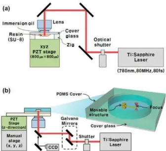
Figure 1(a) shows a schematic diagram of the two-photon stereolithography (TPS) system for the fabrication of 3D micro-structures [21–23]. In the TPS system, a Ti:sapphire laser mode-locked at 80 MHz and a 780 nm wavelength (with pulses of less than 100 fs) is utilized as the light source. The laser beam is tightly focused into the resin volume by using a high numerical aperture (NA: 1.4, with immersion oil) objective lens. The focus of the laser beam is fixed at a given position during the fabrication. A thin glass plate with a droplet of resin (a mixture of SU-8 and photo acid generator) on its surface is then moved by controlling the movements in the x, y, and z directions of a piezoelectric stage with a resolution of 0.1 nm. After the scanning process, the nonpolymerized resin is removed by rinsing with a developer (PGMEA). 3D structures can be fabricated with this single process. A high-magnification CCD camera is used for the optical adjustment of the focused beam, and also for the monitoring of the fabrication process.
After the fabrication of the movable structures, the substrate was sealed by using polydimethylsiloxane (PDMS) slabs with inlet and outlet holes and a cavity. The PDMS cavity was then filled with PGMEA solution to eliminate the flow of solution. Figure 1(b) shows the optical manipulating system. Unlike in the TPS system, which requires a high intensity of photons for two-photon absorption, a continuous wave Ti:sapphire laser was used as the light source. For the precise manipulation of the fabricated movable structure, a beam scanning method that uses a Galvano mirror was employed. This method is commonly used in the manipulation of optical trapping structures because of its ability to produce precise manipulations that are free from tremors in the substrate. In beam scanning systems, however, the working area is limited to the focal plane of the objective lens, which is one important obstacle to overcome in the area of optical manipulation.
#125798 - $15.00 USD Received 22 Mar 2010; revised 21 May 2010; accepted 21 May 2010; published 11 Jun 2010
Fig. 1. Schematic diagrams of (a) the two-photon stereolithography system for the 3D fabrication of movable nano/micro structures, and (b) the optical manipulation system.
3. Optical manipulation with an elastic joint
Fig. 2. (a) CAD model of a single link connected by a pin-joint. The tolerance at the joint causes error. (b), (c), and (d) CCD images of the link during rotation under optical manipulation.
A single link connected by a pin-joint was fabricated by using the TPS process and then optically driven as shown in Fig. 2. The gap between the pin and the hole was set at 500 nm. When the gap was smaller than 500 nm, unintended nano-rod structures were generated between the structures due to the accumulation effect in the weakly polymerized region [24], which can interrupt motion. The length of the link is 30 µm, and the trapping point is located at a distance of 10 µm from the center of the pin-joint. When the link was driven by focusing the laser at the trapping point, the observation point at the end of the link did not exhibit perfect rotational movement with a fixed center point due to the tolerance of the pin-joint.
For the evaluation of the motion achieved with the elastic joint proposed in this work, a single link connected by the elastic joint was tested. First, the optical trapping force was measured by using a cantilever; the dimensions of the link and the joint were then designed according to the results for this force. In this study, a simple nano-scaled thin plate design,
#125798 - $15.00 USD Received 22 Mar 2010; revised 21 May 2010; accepted 21 May 2010; published 11 Jun 2010
which is commonly called a single-layered leaf spring, was chosen for this joint. The movement of the observation point was then used to estimate the movement of the trapping point.
3.1 Measurement of the optical trapping force
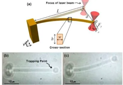
The optical trapping force was measured via a bending test with a cantilever. The high laser power of 5 mW was used for large deformation and stable observation without disturbance of the surrounding fluids; the use of a laser power that exceeds 5 mW would damage the fabricated structures. As shown in Fig. 3(a), a spherical trapping point was placed at the end of the cantilever. To reduce any errors due to deflection in the z-direction, the height of the cantilever was four times larger than its width.
Fig. 3. (a) Schematic diagram of the beam bending test with a cantilever for the measurement of the optical trapping force. CCD images of (b) the cantilever in the initial state, and (c) the cantilever bent by optical manipulation.
When the focus of the laser beam is adjusted onto the trapping point, which is then moved perpendicularly, the cantilever bends a certain distance. If the displacement of the focus is larger than a critical distance, the bent cantilever returns to its original state of elastic deformation. From this maximum displacement of the trapping point, the optical trapping force can be obtained. Figures 3(b) and 3(c) show the initial state and the deflection of the cantilever respectively, as obtained with a CCD camera during the experiment.
First, the diameter of the spherical trapping point that provided the maximum trapping force was determined to be 3 µm by carrying out tests for spheres with diameters of 1, 3, and 5 µm. Thus a sphere with a diameter of 3 µm was used as the trapping point in this study. The trapping forces for the cantilever with the cross-sectional dimension (a width of 0.31 µm and a height of 1.15 µm) were obtained. It was assumed that the deflection of the cantilever is affected dominantly by the trapping force in y direction (Fy)
1 3
3 3
sec( ) sec tan
2 y EI F F L L δ δ θ − ≈ ⋅ = × , (1)
The trapping force (F) was obtained from Eq. (1), where δ is the maximum displacement of the trapping point in the y direction, θ is the slope at the end of the cantilever, L is the length of the cantilever (30 µm), E is the elastic modulus of photo-cured SU-8, which was found to be 4.67 GPa by using a nano-indentation test, and I is the moment of inertia of the cantilever
#125798 - $15.00 USD Received 22 Mar 2010; revised 21 May 2010; accepted 21 May 2010; published 11 Jun 2010
( 3
/ 12
w h for a square). The deflection of the cantilever was measured by increasing the laser power. The scanning speed was set at 1 µm/s, which is slow enough that the influence of the forces of the surrounding fluids can be disregarded. For a laser power of 5 mW, the trapping force was measured to be 13.2 nN.
3.2 Design of the elastic joint
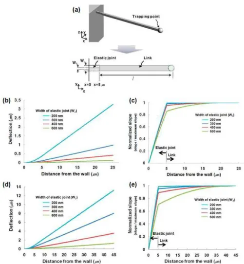
Fig. 4. (a) CAD model of a cantilever composed of a single link and an elastic joint. The trapping point is located at the end of the link. The width and the height of the link are both 1.2 µm, and the height of the joint is 1.2 µm. (b) to (e) The deflection and the normalized slope at each point of the cantilever for joints of various widths when force is applied at the trapping point for links with lengths of (b), (c) 20 µm and (d), (e) 40 µm. Most deformation occurs at the elastic joint. When the width of the joint is as small as one fourth of the width of the link with a length of 20 µm, the joint deforms elastically and little deformation of the link is observed. For a link with a length of 40 µm, the elastic joint needs to be smaller than a sixth of the width of the link.
A cantilever composed of a single link and an elastic joint was designed as shown in Fig. 4(a). The length of the link and the joint were set at 40 µm and 5 µm respectively. The cross-section of the link was set at 1.2 х 1.2 µm2. The joint should be designed to be thin enough to have the concentrated deflection. If there is deflection of the link as well as of the joint in a link system composed of many links and joints, it becomes difficult to estimate the exact position of an objective part. The concentrated deflection according to the width of the joint
#125798 - $15.00 USD Received 22 Mar 2010; revised 21 May 2010; accepted 21 May 2010; published 11 Jun 2010
was estimated through the finite element method (FEM) simulation (ABAQUS). Figure 4(b) shows the deflection at each point of the cantilever with a length of 20 µm for joints of various widths, when 5 nN was applied at the trapping point. The normalized slope increases significantly at the joint, as shown in Fig. 4(c). When the width of the joint is as small as a quarter of the width of the link, the joint deforms elastically and deformation of the link is rarely observed; the slope in the joint contributes 98% of the slope at the end of the cantilever. As the length of the link increases, the width of the joint needs to be thinner. For example, in the case of the link with a length of 40 µm, most of the deformation of 98% is concentrated on the joint when the ratio of the width of the joint versus the width of the link is 1:6, as shown in Figs. 4(d) and 4(e).
3.3. Evaluation of the unit elastic joint structure
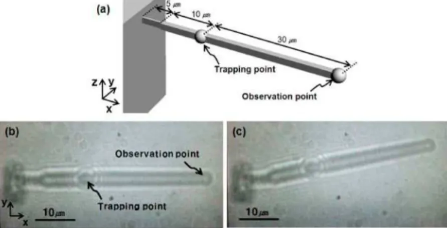
By considering the design parameters obtained above, a cantilever with one degree of freedom for rotation was fabricated and driven. The width ratio of the joint and the link was set at 1:4 (300 nm for the joint, 1.2 µm for the link); the link component of the cantilever then operates almost as a rigid body. The length of the link component is 40 µm. The trapping point and the observation point are located 10 µm from the joint and at the end of the link respectively. The cantilever was driven under a laser power of 5 mW and a driving speed of 8 µm /s.
To evaluate the fabricated structure, the experimental locus of the observation point was compared to the analytical locus. As shown in Fig. 5(a), elastic deformation occurs only at the joint, and highly repetitive movement was observed. The loci nearly coincide, and the error in the y direction was about 50 nm on average. This error might be due to the slight flow of the surrounding fluid.
Fig. 5. (a) CAD model of a cantilever composed of a single link and an elastic joint. The trapping point and the observation point are located 10 µm from the joint and at the end of the link respectively. CCD images of (b) the cantilever with a joint in the initial state, and (c) the cantilever bent by optical manipulation. Only the joint deforms elastically.
4. Multi-link system with elastic joints
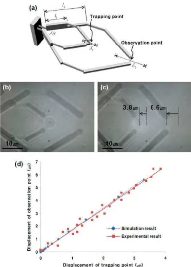
As an example of the use of a joint multi-link system, a multi-link system for the enlargement of movement is proposed, as shown in Fig. 6(a). The proposed structure is composed of double 4-link structures with a ratio of 1:2 in length; these are partially attached to each other. The initial angle (θ) is 74°. The trapping point is located at the edge of the inner 4-link system, and the observation point is located at the edge of the outer 4-link system. By moving the inner 4-link structure, the outer 4-link structure deforms simultaneously. The amplification ratio of the displacements (δ2/δ1) is principally dependent on the ratio of the lengths of the links (l2/l1). For the amplification ratio to depend only on the ratio of the
#125798 - $15.00 USD Received 22 Mar 2010; revised 21 May 2010; accepted 21 May 2010; published 11 Jun 2010
lengths, the design of the elastic joint would need to be optimized so as to induce only a single rotational motion such as in a hinge.
Fig. 6. (a) CAD model of a double 4-link system with an elastic joint for enlargement of the displacement. CCD images of the link system (b) in the initial state and (c) after optical driving. (d) The experimental results and the FEM simulation results for the displacement of the trapping point versus the displacement of the observation point. The movement of the trapped point is precisely transferred by the elastic joint. The ratio was estimated from the geometry of the link system.
To evaluate the effectiveness of the precise motion transformation, the experimental results were compared with the results obtained with FEM simulation. The displacements of the trapping point and the observation point were measured as shown in Figs. 6(b) and 6(c). For an optical drive of 3.8 µm at the trapping point, the amplification ratio of the displacement was estimated to be 1.70 from the results of the FEM analysis and found from the experimental measurements to be approximately 1.66. Thus the movement of the trapped point was transferred precisely by the elastic joint. As shown in Fig. 6(d), the experimental results are in good agreement with the FEM simulation, with a small error of 2.4% on average. This conclusion implies that the optical manipulation working area can be increased to an area larger than the focal region. In addition, the limitations on various and multiple motions can be overcome by using the proposed method.
#125798 - $15.00 USD Received 22 Mar 2010; revised 21 May 2010; accepted 21 May 2010; published 11 Jun 2010
5. Conclusions
In this paper, a multi-link system with an elastic joint was proposed in order to overcome some current limitations on optical manipulation. The small optical trapping force of the laser was determined indirectly by using a cantilever with a width of hundreds of nm and measuring its deflection. Under a laser power of 5 mW, and for a trapping point with a diameter of 3 µm, the trapping force was measured to be 13.2 nN by performing a beam bending test. Considering the physical properties of the material and the trapping force, the appropriate relative dimensions of the link and the joint for concentration of the deformation onto the joint were determined. A system for magnifying the displacement with an enhancement ratio of 1:1.7 and an error within 2.4% was fabricated and evaluated as a test of this approach. The most important feature of the movable device with an elastic joint proposed in this paper is that the movement of this device can be estimated accurately. This advantage means that rotational and linear motion can be amplified by a certain ratio, which enables movement on a large scale. Thus the limitations of the laser scanning range in optical manipulation, which is within several tens of micrometers, can be overcome. Motion transformation with optical manipulation was successfully demonstrated in this study. It is expected that many applications for active devices can be derived from optically driven multi-link structures with elastic joints.
Acknowledgment
This study was supported by the Nano R&D program through the National Research Foundation of Korea funded by the Ministry of Education, Science and Technology (20090082831).
#125798 - $15.00 USD Received 22 Mar 2010; revised 21 May 2010; accepted 21 May 2010; published 11 Jun 2010