1. INTRODUCTION
A Parallel manipulator typically consists of a moving platform that is connected to a fixed base by several serial chains, called limbs. In general, parallel manipulators have some advantages of high speed, payload, accuracy and stiffness over serial manipulators. Among various parallel manipulators, the 6-DOF Stewart-Gough platform has attracted the most interests of researchers and industries, since all the linear actuators are under only tensional/compressive forces. [1,2] However, the manipulator has some disadvantages such as complex forward kinematics, small workspace, and requiring many parts.
To overcome the above shortcomings, parallel mani- pulators with fewer than six degrees of freedom have been investigated.[3~12] Low-DOF parallel manipulators have the advantages of relatively simple forward-kinematics, larger workspace, lower inertia, and requiring less parts over 6-DOF counterparts. A low-DOF parallel manipulator costs less than a 6-DOF counterpart and, hence, it may be more economic to employ such manipulators for applications for which 6-DOF is not necessary. Among low-DOF parallel manipulators, 3-DOF translational parallel manipulators[6~9] and 3-DOF rotational parallel manipulators[10,11] have been focused.
In the first design stage of manipulators requiring high speed, accuracy, and stiffness, the stiffness analysis may be very essential and the most important step. For 6-DOF parallel manipulators, various methods of the stiffness analysis have been published.[12~14] However, the stiffness analysis for low-DOF parallel manipulators has been a little investigated. Among the research results, Zhang and Gosselin[15~18] analyzed low-DOF parallel manipulators with passive constraining limbs. However, the method of using virtual joints is not systematic. It is well known that the Jacobian and stiffness
matrices of a 6-DOF parallel manipulator are 6×6 matrices. However, it is not clear as to what is the best way to express the Jacobian and stiffness matrices of a low-DOF parallel manipulator. For the Jacobian matrix, Joshi and Tsai[19] presented that a 6×6 Jacobian matrix including actuations and constraints should be used in order to analyze all the singularities and to prevent an erroneous design.[20,21] Since the stiffness matrix is basically based on the Jacobian matrix, the stiffness matrix should contain the information on the stiffness due to actuations and constraints and should be a 6×6 matrix even in a low-DOF parallel manipulator.
In this work, the reciprocal screws of actuations and constraints are determined by using the theory of reciprocal screws. The reciprocal screws are the reaction forces due to actuations and constraints, which eventually result in the infinitesimal deflections of joints and links in a serial chain. Using the 6×6 Jacobian matrix from the statics relation, the stiffness matrix becomes the sum of the stiffness matrices of actuations and constraints. The joint stiffness values can be precisely determined by modeling the compliance of joints and links in each serial chain. The stiffness values of a joint can be precisely determined by using the analytic or experimental data of bearings, and the stiffness matrix for revolute and prismatic joints becomes a 6×6 diagonal matrix, where one diagonal element about the rotation axis or along the sliding direction is zero. The links in a serial chain are modeled as Euler-Bernoulli beams. Summing the elastic deformations in all the parts, the total compliance matrix of a serial chain can be obtained. Since the total compliance matrix is generally singular, it is impossible to get the inverse matrix. Instead, multiplying the total compliance matrix by the reciprocal screws yields finite deflections about or along the reciprocal screws. From the finite deflections, the compliance values of springs can be obtained.
Stiffness Analysis of a Low-DOF Parallel Manipulator including the Elastic
Deformations of Both Joints and Links (ICCAS 2005)
Han Sung Kim,* Chang-Rok Shin,* Jin-Ho Kyung,
**Young-Ho Ha,
***Han-Sik Yu,
****and Poong-Soo Shim
***** * School of Mechanical and Automation Engineering, Kyungnam University, Masan, Korea(Tel : +82-55-249-2627; E-mail: [email protected])
** Robot & Control Group, Korea Institute of Machinery & Materials, Daejeon, Korea (Tel : +82-42-868-7885; E-mail: [email protected])
*** Gyeongnam Regional Innovation Agency, Changwon, Korea (Tel : +82-55-264-7815; E-mail: [email protected])
**** Executive Director, EM Korea Co., LTD
***** General Manager, R&D Support Center, World Industries Ace
Abstract: This paper presents a stiffness analysis method for a low-DOF parallel manipulator, which takes into account of elastic deformations of joints and links. A low-DOF parallel manipulator is defined as a spatial parallel manipulator which has less than six degrees of freedom. Differently from the case of a 6-DOF parallel manipulator, the serial chains in a low-DOF parallel manipulator are subject to constraint forces as well as actuation forces. The reaction forces due to actuations and constraints in each limb can be determined by making use of the theory of reciprocal screws. It is shown that the stiffness model of an F-DOF parallel manipulator consists of F springs related to the reciprocal screws of actuations and 6-F springs related to the reciprocal screws of constraints, which connect the moving platform to the fixed base in parallel. The 6×6 stiffness matrix is derived, which is the sum of the stiffness matrices of actuations and constraints. The six spring constants can be precisely determined by modeling the compliance of joints and links in a serial chain as follows; the link can be considered as an Euler beam and the stiffness matrix of rotational or prismatic joint can be modeled as a 6×6 diagonal matrix, where one diagonal element about the rotation axis or along the sliding direction is zero. By summing the elastic deformations in joints and links, the compliance matrix of a serial chain is obtained. Finally, applying the reciprocal screws to the compliance matrix of a serial chain, the compliance values of springs can be determined. As an example of explaining the procedure, the stiffness of the Tricept parallel manipulator has been analyzed. Keywords: stiffness analysis, low-DOF parallel manipulator, joint and link stiffness, reciprocal screw, statics relation
2. STATICS ANALYSIS
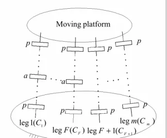
In this work, a low-DOF spatial parallel manipulator with
F-DOF (3≤ F<6) is considered. As shown in Fig. 1, it is assumed that the moving platform is constrained by
m
number of serial-kinematic chains and each limb may have at most one actuator. The limbs having an actuator are indexed first such as i=1 K,2, ,F , and the other limbs without actuator are indexed as i=F+1,F+2,K,m. Let the degree-of-freedom associated with all the joints of the ith limb be defined as the connectivity, Ci, of that limb.
[22,23] Each limb constrains the moving platform by 6−Ci number of constraints, and the total number of all the independent constraints should be six.
For the statics analysis, let us consider the case that an external wrench is applied on the moving platform. For a low-DOF parallel manipulator, the wrench is equilibrated with the reaction forces by F number of actuators and 6-F number of constraints. In order to determine the reaction forces by actuators and constraints, we will use the theory of reciprocal screws.[22,24,25] First, the instantaneous twist of the moving platform needs to be expressed as a linear combination of the unit twists of 1-DOF joints consisting of each limb by, [26]
∑
= = Ci j i j i j P 1 , , ˆ ˆ S T θ&for i=1,2,K,m (1) where TˆP and Sˆ denote the twist of the moving platform and the unit twist expressed in the axis coordinate,[24] and
i j,
θ
&denotes the joint rate. The subscripts, i and j denote the limb number and the joint number in the ith limb, respectively.
As the follows, the reciprocal screws in the ith limb can be determined. [19] First, those screws that are reciprocal to all the joint screws form a (6−Ci) reciprocal screw system,
defined as the reciprocal screws of constraints. Let
ˆs
c ,,kidenote the kth reciprocal screw of constraints of the ith limb. Taking the orthogonal product of both sides of Eq. (1) with each of the
(
6
−Ci)
reciprocal screws of constraints,)
6
(
−Ci reciprocal screws of constraints can be identified byFig. 1 Structure of an F-DOF parallel manipulator.
(Note: a: active joint, p: passive joint)
0
ˆ
ˆ
T,, p= i k c T sfor
k=1
,
2
,
K,
(
6
−Ci)
(2)where
sˆ
denotes the unit screw expressed in the ray coordinate.[24]Second, when the actuators of the ith limb are locked, the dimension of the reciprocal screw system increases by n
(n=0or 1). Those screws that are reciprocal to all the passive joint screws form a (6−Ci+n) reciprocal screw system. Clearly, this (6−Ci+n) reciprocal screw system includes the (6−Ci) reciprocal screw system identified earlier as a subset. Hence, additional reciprocal basis screws that are reciprocal to all the passive joint screws and don’t belong to the (6−Ci) system are defined as reciprocal screws of actuations,
ˆs
a,i, and can be determined by0
ˆ
ˆ
, p′= T i aT s (3)where T
ˆ
p′ is a linear combination of the unit twists of passive joints.From the procedure, we can determine six independent reciprocal screws. Ignoring the gravity, an external wrench is equilibrated with the reaction forces by actuators and constraints along the reciprocal screws given by
)] ˆ ˆ ( ) ˆ ˆ [( ] ˆ ˆ [ ˆ , 6 , , 6 , , 1 , , 1 , 1 , 6 , 1 , 6 , 1 , 1 , 1 , 1 , , , 1 , 1 , m i C c m i C c m c m c i C c i C c c c F a F a a a − − − − + + + + + + + + + = s s s s s s w
τ
τ
τ
τ
τ
τ
L L L L (4)where the wrench expressed in the ray coordinate is T
T T, ]
[
ˆ f m
w
=
when f andm
denote the force and moment vectors at the end-effector.τ
a andτ
c denote the magnitudes of the reaction forces by actuators and constraints, respectively. Eq. (4) may be rewritten in the forms of matrices and vectors byτ τ τ
wˆ
=
Ja a+
Jc c=
J (5)where the Jacobian matrix of actuations and the Jacobian matrix of constraints are given by[19]
[
]
F F a a a R J = ∈ 6× , 1 , ˆ ˆ s s L and (6)[
]
6(6 ) , 6 , , 1 , 1 , 6 , 1 , 1 , ˆ ˆ ˆ ˆ F m i C c m c i C c c c R J × − − − ∈ = s L s L s L s . (7)The overall Jacobian matrix is obtained by
[
]
∈
6×6=
J
J
R
J
a c . (8) In Eq. (5), 1 , 1 , , , ] [ ∈ × = T F F a a a τ Lτ Rτ denotes the actuator vector,
1 ) 6 ( , 6 , , 1 , 1 , 6 , 1 , 1 , , , , , , , ] [ − × − − ∈ = T F m i C c m c i C c c c τ Lτ LLτ Lτ R τ denotes
the reaction vector by constraints, and =[ , T]T∈R6×1
c T a τ τ
τ is
the overall joint vector.
3. STIFFNESS ANALYSIS
In this paper, it is assumed that the moving platform is rigid and the major sources of compliance come from the flexibility of the bearings, links, mechanical transmission mechanisms and control systems.[22] The reciprocal screws may be classified into three categories; zero-pitch reciprocal
platform
Moving
a
)
(
leg
F
C
F)
(
1
leg
C
1)
(
1
leg
F
+
C
F+1)
(
leg
m
C
mp
p
p
p
p
a
p
p
p
screw, infinitesimal-pitch reciprocal screw, and finite-pitch reciprocal screw expressed respectively by
×
=
s
r
s
sˆ
,
=
s
0
sˆ
,
+
×
=
s
s
r
s
s
h
ˆ
. (9)where
s
is the unit directional vector of a screw, r is the position vector from the reference frame to a screw, and h is the pitch of a screw. The physical meanings of zero- and infinite-pitch reciprocal screws are pure force and pure couple. Although the reciprocal screw may be a nonzero finite-pitch screw in a special case, it is not considered in this work.When pure force is exerted on a limb with some compliance, it generates infinitesimal translational motion along the line of the force. On the other hand, when pure couple is applied to a limb, it generates infinitesimal rotational motion about the axis of the couple. Hence, the infinitesimal translational and rotational motions can be modeled as the deflection of a linear spring placed along the line of the force, and the deflection of a rotational spring with the axis of the couple, respectively. As seen in the previous section, it can be modeled that the moving platform is supported by six independent springs, since there exist six reciprocal screws in a general case. Among the springs, F springs are related to the actuations and 6-F springs are related to the constraints. Let
i a
k
, (i=
1,2,L,F) be defined as the spring constant of actuations, andk
c,i (i=
F+
1,L,6) be defined as that of constraints. The relation between the force and deflection of springs can be expressed by[ ]
a a a k qτ
=
δ
, and τc=
[ ]
kcδ
qc (10) where[ ]
ka and[ ]
kc denote the diagonal matrices with the diagonal elements ofk
a,i andk
c,i, respectively, anda q
δ
andδ
qc are the infinitesimal displacement vectors of actuations and constraints. By applying the principle of virtual work, the following equation can be obtained byc T c a T a T D τ q τ q wˆ
δ
ˆ =δ
+δ
(11) whereδ
Dˆ =[δ
xT,δ
θT]T denotes the infinitesimal twist expressed in the axis coordinate, whenδ
x andδ
θ are the infinitesimal translational and rotational displacements at the end-effector. Substituting Eq. (5) into Eq. (11) yieldsc T c a T a T c T c T a T aJ D τ J D τ q τ q τ
δ
ˆ+δ
ˆ =δ
+δ
(12) Since Eq. (12) is valid for any value of τa and τc, one can write D qδ
ˆδ
T a a=J , andδ
qδ
Dˆ T c c =J . (13)Substituting Eq. (10) into Eq. (11) gives c c T c a a T a T D q k q q k q wˆ
δ
ˆ =δ
[ ]δ
+δ
[ ]δ
. (14) Using Eq. (13), Eq. (14) can be rewritten byD D D D D wˆ δˆ δˆ [ ] δˆ δˆ [ ] Tδˆ c c c T T a a a T T J k J J k J + = . (15)
Since Eq. (15) is also valid for any value of
δ
Dˆ, the stiffnessmapping between applied wrench and infinitesimal twist at the end-effector is obtained in terms of the stiffness matrix, K
D
wˆ =K
δ
ˆ (16)where the overall stiffness matrix is obtained with the sum of the stiffness matrices of actuations and constraints given by
T c c c T a a a
k
J
J
k
J
J
K
=
[
]
+
[
]
(17)Using the overall Jacobian matrix, the overall stiffness matrix may be simplified by T
J
k
J
K
= [ ] (18) whereJ
=[
J
aJ
c]
and = ] [ 0 0 ] [ ] [ c ak
k
k
.It is noted that the stiffness matrix for a low-DOF parallel manipulator has a similar form with a full-DOF parallel manipulator.[12-13] The stiffness matrix of a full-DOF parallel manipulator is expressed only with the stiffness matrix of actuations, since any constraints do not exist. On the other hand, the stiffness matrix of a low-DOF parallel manipulator should be expressed with the stiffness matrices of actuations and constraints. Hence, the intuitive approach of using a partial stiffness matrix may lead to erroneous results.
4. COMPLAINCE MODELING OF SERIAL CHAINS In this section, we present a method to determine the spring constants related to actuations and constraints in a serial chain. In deriving the compliance model of a serial chain, the flexibility in joints and links is considered. First, without loss of generality, only revolute and prismatic joints are considered, since a spherical joint is equivalent to three intersecting non-coplanar revolute joints, a universal joint is equivalent to two intersecting revolute joints, a cylindrical joint is equivalent to the sum of a revolute joint and a prismatic joint along the revolute joint axis, and so on. The compliance matrix of a 1-DOF joint is given by
=
a r r a l r l r l Jc
c
c
c
c
c
C
, , , , , ,0
0
0
0
0
0
0
0
0
0
0
0
0
0
0
0
0
0
0
0
0
0
0
0
0
0
0
0
0
0
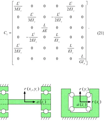
θ θ θ (19)where the axis of a joint is aligned with the z-axis of a local frame, and the radial direction of a joint is placed on the xy plane of a local frame as shown in Fig. 2. The subscripts,
l
and
θ
denote the linear and rotational stiffnesses, and the following subscripts,a
andr
denote the axial and radial directions. It is noted thatc
θ,a=∞, for a revolute joint, and∞ =
a l
c
, , for a prismatic joint.Second, the links in a serial chain are considered as Euler-Bernoulli beams, implying that the shear effect and inertia of rotation of the beam section are ignored, and beam sections stay plane and perpendicular to the neutral axis. Forces and moments elastically deform the tip of each link.
The elastic deformations at the tip of a link are written as follows: y y x x x
M
EI
L
F
EI
L
2
3
2 3+
=
δ
x x y y yM
EI
L
F
EI
L
2
3
2 3−
=
δ
, zF
zAE
L
=
δ
, x x y y xM
EI
L
F
EI
L
+
−
=
2
2θ
, y y x x yM
EI
L
F
EI
L
+
=
2
2θ
, z p zM
GI
L
=
θ
(20)where
A
andL
are the area and length of a link,E
is the modulus of the longitudinal elasticity,G
is the modulus of the transverse elasticity.I
x,I
y andI
z are the moment of inertias about the x, y, and z axes, respectively.I
p is the polar moment of inertia. Then, the compliance matrix of a link is given by − − = p y x x y x y y x L GI L EI L EI L EI L EI L AE L EI L EI L EI L EI L C 0 0 0 0 0 0 0 0 0 2 0 0 0 2 0 0 0 0 0 0 0 0 2 0 3 0 0 2 0 0 0 3 2 2 2 3 2 3 . (21) ) , ( xi yi r ) ( zi a ) ( yi r ) ( xi r ) ( zi aFig. 2
Compliance model of 1-DOF joints.
i z i y i x 1 + i z 1 + i y 1 + i x x δ z δ y δ x θ y θ z θ 1 + ′ i x 1 + ′ i y 1 + ′ i z L i Link
Fig. 3
Compliance model of a link.
The infinitesimal twist at the ith joint or the ith link expressed in the ith local frame can be expressed by
i i i i i iδDˆ =C wˆ (22) where i
iC denotes the compliance matrix of the ith part expressed in the ith local frame and iwˆi denotes the wrench applied on the ith part expressed in the ith local frame. Expressing the infinitesimal twist and wrench with respect to the moving frame (P) gives
i i P i i T D Dˆ δˆ δ = and i i T P i i T w wˆ = − ˆ (23)
where the transformation matrix of screws from the ith frame to the moving frame is given by
= × R R p R T P i P i i P P i P i 3 3 0 ˆ (24) where PR
i denotes the rotation matrix from the ith frame to the moving frame and Ppˆi denotes the skew-symmetric matrix representing the vector from the origin of the moving frame to that of the ith local frame expressed in the moving frame. The total deflection of a serial chain can be calculated by the sum of all the deflection in joints and links given by
∑
= = n i T P i i i P iT C T 1 ˆ ) ( ˆ w D δ . (25)Therefore, the compliance of a serial chain expressed in the moving frame can be written by
∑
= = n i T P i i i P iT C T C 1 ) ( . (26)The joint compliance values related to the reciprocal screws of actuations and constraints are calculated by
f x⋅ =δ l c and cθ =δθ⋅m (27) where f =1 and m =1. 5. EXAMPLE
In this section, the stiffness of the Tricept manipulator is analyzed, in order to explain the suggested method. As shown in Fig. 4, the Tricept manipulator has three actuated SPS (Spherical-Prismatic-Spherical) limbs and one passive UP (Universal-Prismatic) limb.[5,17] The limbs with actuators are numbered first and the passive limb is indexed as i=4. Since the connectivity of the three actuated SPS limbs is six, there exist no reciprocal screws of constraints in the three actuated limbs. Also, there exists no reciprocal screw of actuations in the passive limb.
The reciprocal screw of actuations of the ith limb 3
2, 1,
for i= is a zero-pitch screw passing through the two centers of spherical joints,
× = i i i i a s b s sˆ,
for i=1,2,3 (28)
where si is a unit vector along the prismatic joint and i
i =
PB
b .Since the connectivity of the passive limb is
C
4=3, theinfinitesimal twist of the end-effector can be expressed as a linear combination of three instantaneous twists:
4 , 3 4 , 3 4 , 2 4 , 2 4 , 1 4 , 1
ˆ
ˆ
ˆ
ˆ
S
S
S
T
p=
θ
&
+
θ
&
+
d
&
(29)where
−
×
=
4 , 1 4 , 1 4 , 1ˆ
s
s
p
S
, −
×
=
4 , 2 4 , 2 4 , 2ˆ
s
s
p
S
,
=
0
s
S
3,4 4 , 3ˆ
,and p=OP. The reciprocal screws of constraints can be obtained as follows: × − = 4 4 1 , ˆ s p s sc
,
× − = 5 5 2 , ˆ s p s sc,
= 6 3 , ˆ s 0 sc (30) where s4=s2,4×s3,4,
s5=s2,4, and
s6=s1,4×s2,4.
Therefore, the Jacobian matrices of actuations and constraints can be obtained by
×
×
×
=
3 3 2 2 1 1 3 2 1s
b
s
b
s
b
s
s
s
aJ
, (31)
×
×
=
6 5 5 4 4 5 4s
s
b
s
b
0
s
s
cJ
(32)where
b4=b5=−p.
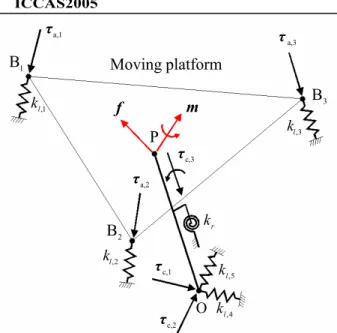
As shown in Fig. 5, each actuated limb can be modeled as a linear spring along the prismatic joint, since the reciprocal screw of actuations is pure force. Similarly, for the two reaction forces and one reaction moment, the passive limb can be modeled as two linear springs and one rotational spring. Using Eq. (18), the stiffness matrix of the Tricept manipulator can be obtained by + × × × × =
∑
∑
∑
∑
= = = = T r i T i i l i i i T i l i i i T i i l i i T i l i k k k k k K 6 6 5 1 5 1 5 1 5 1 ) ]( )[ ( ] )[ ( ) ]( [ ] [ s s s b s b s s b s b s s s (33)where
[
k
l]
=
diag
[
k
l,1,
k
l,2,
k
l,3,
k
l,4,
k
l,5]
andk
r denotes the rotational spring constant.The next step is to find the six spring constants from the information on the compliance of the joints and links consisting serial chains. First, the compliance of an SPS chain
is modeled. It is noted that the chain is symmetric about the line,
A
iB
i. So, it is convenient to align the z axes of all the frames along the line. The moving coordinate frame locates at the center of the upper spherical joint. Since the spherical joint can be considered as three intersecting non-coplanar revolute joints, the compliance matrix of a spherical joint expressed in the corresponding local frame can be modeled as]
,
,
,
,
,
[
∞
∞
∞
=
S l S l S l Sdiag
c
c
c
C
. (34)In a similar manner, the compliance matrix of a linear actuator expressed in the corresponding local frame is given by
]
,
,
,
,
,
[
, , , , , , L a L r L r L a l L r l L r l Ldiag
c
c
c
c
c
c
C
=
θ θ θ . (35) where L a lc
, is the compliance of a linear actuator, and the other diagonal elements are the compliances of a prismatic joint. The fixed link length and area are defined asL
1 and1
A
, the moving link length and area are defined asL
2 and 2A
, and the total limb length isL
. The total compliance of an SPS serial chain is the sum of compliances of the lower andupper spherical joints, linear actuator, and fixed and moving links. The compliance along the line,
A
iB
i, can be easily calculated by E A L E A L c c k c S l L a l i l i l 2 2 1 1 , 1 , , = = +2 + + − , for i=1,2,3. (36) Second, the total compliance of the UP serial chain is thesum of compliances of the universal joint, prismatic joint and the fixed and moving links. Expressing the compliance of the universal joint in the
O
−
x
uy
uz
u yields] , , , , , [ , , , , U z U z l U p l U p l U diagc c c c C = ∞∞ θ (37) where U p l c, and U z l
c, are the linear compliances of the xy plane and the z-axis, and U
z
cθ, is the rotational compliance about the z-axis. The z-axis of the local frame of the prismatic joint is along the limb,
OP
. The compliance of the prismatic joint is given by]
,
,
,
,
,
[
, , , , , P a P r P r P r l P r l Pdiag
c
c
c
c
c
C
=
∞
θ θ θ . (38)Using Eqs. (26) and (27), the compliances related to the reciprocal screws of constraints, i.e., τc,1
,
τc,2, and
τc,3can be obtained by (refer to Fig. 5)
Fig. 4 Kinematic model of a Tricept parallel manipulator.
1
B
1s
x
y
u
v
w
P
p
ib
2B
3B
2A
3A
joint
-S
joint
-P
joint
-U
s
1,4 3s
4 , 2s
2s
4 , 3s
ia
O
joint
-S
joint
-P
1A
platform
Moving
Fig. 5 Stiffness model of a Tricept parallel manipulator.
x
y
z
P
2L
1L
yθ
θ
x)
(
x
ux
y
z
uz
uy
O
xθ
Fig. 6 Definition of the local frames of an UP serial chain.
)] 2 cos( ) ( [ 2 1 , , , , 2 1 , , 1 4 , 4 , y U z l U p l U z l U p l P r P r l l l k c c LL c c c c c = − = − θ + + + − θ 2 1 , , , 1 5 , 5 , k c c c LL c P r U p l P r l l l = − = + − θ )] 2 cos( ) ( [ 2 1 , , , , , 1 6 , y P r P a U r U a U z r l k c c c c c c = − = θ + θ + θ + θ − θ θ (39)
It is noted that in Eq. (39), only joint compliances are considered.
6. CONCLUSION
In this paper, the stiffness analysis for a low-DOF parallel manipulator using the theory of reciprocal screws and considering the elastic deformation in joints and links by the reciprocal screws is presented. For an F-DOF parallel
manipulator, it is derived that there exist F number of
reciprocal screws related to actuations and 6-F number of
reciprocal screws related to constraints. The stiffness matrix for a low-DOF parallel manipulator becomes the sum of the stiffness matrices of actuations and constraints. The practical values of spring constants are obtained by modeling the compliances of joints and links in each serial chain. Finally, the methodology is applied to the 3-DOF Tricept parallel manipulator. In the further works, this analytic method will be used in the design optimization of a parallel-kinematic machine tool and the effectiveness of the suggested stiffness analysis method will be verified through experiments.
ACKNOWLEDGMENTS
This work was supported by MOCIE(Ministry of Commerce, Industry and Energy Republic of Korea) and Gyeongsangnam-do.
REFERENCES
[1] Stewart, D., 1965, “A Platform with Six Degrees of Freedom,” Proc. Institute of Mechanical Engr., London,
England, Vol. 180, pp. 371~386.
[2] Gough V. E., and Whitehall S. G.., 1962, “Universal Tire Test Machine,” Proceedings 9th Int. Technical Congress F.I.S.I.T.A., Vol. 117, pp.117~135.
[3] Clavel, R. 1988, “Delta, a Fast Robot with Parallel Geometry,” 18th International Symposium on Industrial Robots, Sydney, Australia, pp. 91-100.
[4] Pierrot, F., Reynaud, C., and Fournier, A., 1990, “DELTA: A Simple and Efficient Parallel Robot,”
Robotica, Vol. 8, pp. 105~109.
[5] Siciliano, B., 1999, “The Tricept Robot: Inverse Kinematics, Manipulability Analysis and Closed-Loop Direct Kinematics Algorithm,” Robotica, Vol. 17, pp.
437~445.
[6] Tsai, L. W. and Joshi, S., 2000, “Kinematics and Optimization of a Spatial 3-UPU Parallel Manipulator,”
ASME Journal of Mechanical Design, Vol. 122, No. 4,
pp. 439~446.
[7] Wenger, P., and Chablat, D., 2000, “Kinematic Analysis of a New Parallel Machine Tool: The Orthoglide,”
Advances in Robot Kinematics, Edited by J. Lenarcic
and M. L. Stanisic, Kluwer Academic Publishers, London, pp. 305~314.
[8] Kim, H. S., and Tsai, L. W., 2003, “Design Optimization of a Cartesian Parallel Manipulator,” Journal of Mechanical Design, Vol. 125, No. 1, pp. 43~51.
[9] Kim, H. S., and Tsai, L. W., 2002, “Evaluation of a Cartesian Parallel Manipulator,” 8th International Symposium on Advances in Robot Kinematics, 24~28
June, Caldes de Malavella, Spain, pp. 21~28.
[10] Gosselin, C. M., and Angeles, J., 1989, “The Optimum Kinematic Design of a Spherical Three-Degree-of- Freedom Parallel Manipulator,” ASME Journal of Mechanisms, Transmissions, and Automation in Design,
Vol. 111, No. 2, pp. 202~207.
[11] Fang, Y. F., and Tsai, L. W., 2004, “Structure Synthesis of a Class of 3-DOF Rotational Parallel Manipulators,”
IEEE Trans. on Robotics Automation, Vol. 20, No. 1, pp.
117~121.
[12] Gosselin, C., 1990, “Stiffness Mapping of Parallel Manipulators,” IEEE Transaction on Robotics and Automations, Vol. 6, pp. 377~382.
m
f
1 , lk
1B
2B
3B
3 , lk
platform
Moving
P
c,1τ
a,1τ
a,3τ
c,3τ
a,2τ
c,2τ
2 , lk
5 , lk
4 , lk
rk
O
[13] Griffis, M., and Duffy, J., 1993, “Global Stiffness Modeling of a Class of Simple Compliant Couplings,”
Mechanism and Machine Theory, Vol. 28, No. 2, pp.
207~224.
[14] Tahmasebi, F. and Tsai, L. W., 1995, “On the Stiffness of a Novel Six-Degrees-of-Freedom Parallel Manipulator,” Journal of Robotic Systems, Vol. 12, No.
12, pp. 845~856.
[15] Zhang, D., and Gosselin, C. M., 2001, “Kinetostatic Modeling of N-DOF Parallel Mechanisms with a Passive Constraining Leg and Prismatic Actuators,”
ASME Journal of Mechanical Design, Vol. 123, pp.
375~381.
[16] Zhang, D., and Gosselin, C. M., 2002, “Kinetostatic Modeling of Parallel Mechanisms with a Passive Constraining Leg and Revolute Actuators,” Mechanism and Machine Theory, Vol. 37, pp. 599~617.
[17] Zhang, D., and Gosselin, C. M., 2002, “Kinetostatic Analysis and Design Optimization of the Tricept Machine Tool Family,” ASME Journal of Manufacturing Science and Engineering, Vol. 124, pp.
725~733.
[18] Zhang, D., and Gosselin, C. M., 2002, “Parallel Kinematic Machine Design with Kinetostatic Model,”
Robotica, Vol. 20, pp. 429~438
[19] Joshi, S. A., and Tsai, L. W., 2002, “Jacobian Analysis of Limited-DOF Parallel Manipulators,” Journal of Mechanical Design, Vol. 124, pp. 254~258.
[20] Zlatanove, D., Bonev, I., and Gosselin, C., 2002, “Constraint Singularities as C-Space Singularities,”
Proceedings of the 8th Advances in Robot Kinematics,
edited by J. Lenarcic and F. Thomas, Kluwer Academic Publishers, pp. 183~192.
[21] Han, C., Kim, J., Kim J., and Park, F. C., 2002, “Kinematic Sensitivity Analysis of the 3-UPU Parallel Mechanism,” Mechanism and Machine Theory, Vol. 37,
pp. 787~798.
[22] Tsai, L. W., 1999, Robot Analysis: The Mechanics of Serial and Parallel Manipulators, John Wiley & Sons,
New York, NY.
[23] Tsai, L. W., 2000, Mechanism Design: Enumeration of Kinematic Structures According to Function, CRC Press,
pp. 221~247.
[24] Duffy, J., 1996, Statics and Kinematics with applications to Robotics, Cambridge University Press.
[25] Ball, R. S., 1990, A Treatise on the Theory of Screws,
Cambridge University Press, Cambridge.
[26] Mohamed, M. G., and Duffy, J., 1985, “A Direct Determination of the Instantaneous Kinematics of Fully Parallel Robot Manipulators,” ASME J. Mech., Transm., Autom. Des., Vol. 107, pp. 226~229.
[27] Yoon, W.K., Suehiro, T., and Tsumaki, Y., 2004, “Stiffness Analysis and Design of a Compact Modified Delta Parallel Mechanism,” Robotica, Vol. 22, pp.