Conceptual Thermal-Hydraulic Design and Analytical Assessment
of Spent Fuel Storage Pool for the Integral Reactor
Min-Hwan Kim, Jong-In Kim, Sung-Kyun Zee,
Korea Atomic Energy Research Institute, P.O.Box 105, Yuseong, Daejeon, Korea, 305-350, [email protected]
1. Introduction
KAERI has developed a design concept of the fuel handling system the integral reactor under development[1][2][3]. The fuel handling system is composed of fresh fuel handling subsystem, reactor refueling subsystem, and spent fuel handling subsystem. The concern of this paper is focused on spent fuel handling system, especially spent fuel storage pool. Spent fuel pool has racks that store spent fuels unloaded from reactor core. The main function of spent fuel storage pool is not only to safely store spent fuel in the rack but also to maintain its temperature state within a given design limit.
The purpose of this paper is to introduce the design concept of spent fuel storage pool for the integral reactor and to determine the temperature state of cooling water with different options of fuel lack loading using analytical method.
2. Thermo-hydraulic design description of spent fuel storage pool
Spent fuel storage pool is intended to install and store SFC(spent fuel channel) after unloading from the reactor, canisters with leaky SFC, and canisters with spent CEA(control element assembly) and ICI(in-core instrumentation). When selecting the parameters and dimensions of the spent fuel storage pool, taken into account were total required pool capacity and necessary spent fuel channel storage conditions.
The spent fuel storage pool is shown in Figure 1. Spent fuel storage pool is a concrete rectangular cavity filled with water, where the walls and bottom are lined with stainless steel. Spent fuel racks are installed into spent fuel storage pool in vertical position. The pool houses eight identical racks, each designed to store 295 leak-tight spent fuel channel, five canisters with spent CEA and ICI and six canisters with leaky SFC, which allows arranging six cores unloaded under schedule (6×295pcs.) and two cores unloaded off schedule (2×295pcs.), as well as 40 canisters with spent CEA and ICI and 48 canisters with leaky SFC.
In case of external pipeline leakage, normal operation and prevention of the pool draining, nozzles for cooling water supply/removal are provided, laid in the upper part of the spent fuel storage pool.
Water circulation in spent fuel storage pool is provided under dynamic effect of downflows coming out of the feedwater tube, and convective heated water upflows coming out of the spent fuel storage racks. Combined effect of the discharge jet downflow and ascending currents at the spent fuel storage rack outlet causes the development of natural circulation circuit in the lower part of the spent fuel storage pool, where the racks are located. In the natural circulation circuit cooling water is supplied to the downcomer section between the rack and the pool wall, spreads over the bottom and then is supplied to SFC inlet. After being heated in the heat-generating part of SFC, water ascends and is supplied through bypass slots in SFA suspension to annular channel between the suspension and the guide tube.
Heated water flows to the inter-tube space from the annular channel through upper bypass slots. From this space the water ascends through the holes in the rack upper plate into the space above the racks in form of local convective jets. In this space the ascending spreading heated water jets mix with the descending and broadening cooling water flow jet, which is forcedly supplied to the spent fuel storage pool, and then return as mixing currents to the downcomer section of the natural circulation circuit.
Racks(2x4) Nozzles for cooling Water supply Nozzles for cooling water removal
Guide Tube
SFC Bypass Slots
Racks(2x4) Nozzles for cooling Water supply Nozzles for cooling water removal
Guide Tube
SFC Bypass Slots
Figure 1. Configuration of spent fuel storage pool
3. Analytical estimations of spent fuel storage pool thermo-hydraulic parameter
The purpose of analytical estimations is to determine temperature state of cooling water in spent fuel storage pool with different options of fuel rack loading and to verify whether the temperature state satisfies with design requirement, bulk average pool temperature should be maintained no higher than 49℃ under normal spent fuel pool heat load conditions including refueling and 60℃ under conditions of maximum heat generation.
During spent fuel reloading the reactor core containing 295 fuel channels is fully unloaded. Scheduled refueling cycle is 3 years and emergency off-loads are assumed to be 0.5 year and 1 year after previous normal discharge. Duration of SFC storage in reactor is 10 days, after its shutdown before reloading into spent fuel storage pool. Duration of one core SFA unloading from reactor is 5 days. Therefore scheduled unloading of all SFA, which have operated for 3 years in reactor, into any of 8 pool racks is completed in 15 days after reactor shutdown. The residual heat release rate of one just-unloaded core located in the rack is 125 kW.
3.1 Analysis procedure
In case of forced supply of descending water flow to spent fuel storage pool through the feed pipe, the temperature of cooling water supplied to downcomer section of natural circulation circuit in approximations was calculated on the basis of the following ratios
Transactions of the Korean Nuclear Society Autumn Meeting Busan, Korea, October 27-28, 2005
[
t L t]
Ltind = inSFSP+( −1)⋅ outrack
where tind , tinSFSP and toutrack are cooling water temperature at the inlet of downcomer section, supplied to spent fuel storage pool, and at spent fuel storage rack outlet. L=m&f m&SFSP is relative mass flow rate of descending convective currents near the inlet of natural circulation circuit downcomer section where m&f is for descending broadening water flow taking into account descending mixing currents and m&SFSPis for cooling water supplied through feed pipe to spent fuel storage pool.
Temperature of cooling water removed from spent fuel storage pool was calculated according to expression
SFSP р SFSP in SFSP out t Q c m t = + ∑ ⋅& ,
where toutSFSPis temperature of cooling water removed from spent fuel stoage pool, QΣ is total residual heat release rate of all cores located in spent fuel storage pool.
Heatup of cooling water circulating through fuel storage rack in natural circulation mode was calculated on the basis of balance ratio: rack р rack h Q с m t = ⋅& ∆ ,
where ∆th, °С is heatup of cooling water in spent fuel storage
rack, Qrack is residual heat release rate of SFC located in spent
fuel storage rack, and m&rackis mass flow rate of cooling water circulating through spent fuel storage rack in natural circulation conditions.
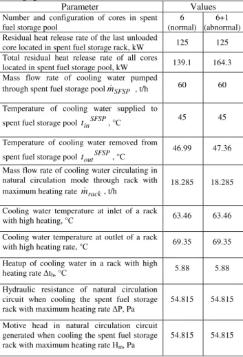
Table 1 Thermal-hydraulic parameter for spent fuel storage pool
Parameter Values
Number and configuration of cores in spent fuel storage pool
6 (normal)
6+1 (abnormal) Residual heat release rate of the last unloaded
core located in spent fuel storage rack, kW 125 125 Total residual heat release rate of all cores
located in spent fuel storage pool, kW 139.1 164.3 Mass flow rate of cooling water pumped
through spent fuel storage poolm&SFSP , t/h 60 60 Temperature of cooling water supplied to
spent fuel storage pool tinSFSP, °С
45 45
Temperature of cooling water removed from spent fuel storage pool toutSFSP, °С
46.99 47.36 Mass flow rate of cooling water circulating in
natural circulation mode through rack with maximum heating rate m&rack, t/h
18.285 18.285
Cooling water temperature at inlet of a rack
with high heating, °С 63.46 63.46 Cooling water temperature at outlet of a rack
with high heating rate, °С 69.35 69.35 Heatup of cooling water in a rack with high
heating rate ∆th, °С 5.88 5.88
Hydraulic resistance of natural circulation circuit when cooling the spent fuel storage rack with maximum heating rate ∆Р, Pa
54.815 54.815
Motive head in natural circulation circuit generated when cooling the spent fuel storage rack with maximum heating rate Нm, Pa
54.815 54.815
Hydraulic resistance of natural circulation circuit in the pool was determined taking into account local hydraulic resistance and pressure losses to overcome friction resistance in structural elements of circulation paths:
∆Р = i h k i W D l ⋅ ⋅ ⋅ + Σ =
Σ
ς λ ρ 2 2 1 ,Flow rate of cooling water circulating through a rack with high heating rate in natural circulation mode was calculated by iterative analysis based on the condition of achieving equal hydraulic resistance of natural circulation circuit and motive head developed in this circuit :
∆Р = Нm =
(
j j)
n j h g⋅ ⋅∑
= ρ 1 ,where Нm is motive head of natural circulation circuit, ρj is
cooling water density at j-th section of natural circulation circuit, and hj is height of j-th section of natural circulation
circuit.
3.2 Analysis results
Thermal-hydraulic parameters of spent fuel storage pool were considered when it contains:
- six cores unloaded under schedule
- six cores unloaded under schedule and one just-unloaded core (off schedule), which has operated in reactor for 0.5 year
Table 1 summarizes the results of analysis of flow rate, heat release rate and temperature state of cooling water in spent fuel storage pool with different number of unloaded cores.
4. Conclusion
The calculated thermal-technical characteristics of the spent fuel storage pool allow drawing the following conclusions.
Maximum total residual heat load is observed when there are six cores unloaded under schedule plus one just-unloaded core (off schedule) after 0.5 years of operation in the core. In this case, maximum residual heat load from SFA reaches 164.3 kW.
If total residual heat releases from SFC arranged in the spent fuel storage pool are maximum and if water with the inlet temperature of 45ºC is pumped to the pool at the flow rate of 60 t/h, the maximum temperature of cooling water at the pool outlet does not exceed 47.4°C, which means current design satisfies the design requirement with enough margin. Maximum local temperature of cooling water at the outlet of the spent fuel storage rack with maximum heating rate, which is loaded with just-unloaded SFC, amounts to 69.4°С, much lower value than local boiling.
ACKNOWLEDGEMENT
This study has been carried out under the Nuclear R&D Program by MOST
REFERENCES
[1] M. H. Kim et al, Conceptual Design of New Fuel Storage and Handling Subsystem for the Integral reactor, Proceedings of the Korean Nuclear Society Spring Meeting, 2005. [2] J. S. Lee et al, Reactor Refueling System Conceptual Design for Integral Reactor, Proceedings of the Korean Nuclear Society Spring Meeting, 2005.
[3] J. Y. Yu et al, Conceptual Design of Spent Fuel Storge and Handling for SMART-P Plant, Proceedings of the Korean Nuclear Society Spring Meeting, 2005.