Journal of International Conference on Electrical Machines and Systems vol. 3, no. 4, pp. 422~427, 2014 422
Simple LED driver with Constant Current Control
Seong-Mi Park*, Sung Geun Song**, and Sang Hun Lee***
Abstract
– In this paper, simple LED driver is proposed. The proposed driver has simpleconstruction having series capacitor, bridge rectifier, and adjustable regulator IC. Constant current control is possible with the use of TL431Z. The proposed in this paper, current is greater than the rating of the load, the current controller device measures the increased current in the circuit, and turned-on so that the current will be shared. Thus current control device makes the circuit more reliable, longevity as well as increase the luminous efficacy of the LED light. The simulation and experimental results are presented to show the validity of the proposed circuits.
Keywords:
LED driver, LED lights driver structure, Current control device1. Introduction
LED lighting industry provides various effects as well as sources of technology based on practical use of LED technology in order to develop the industry from the perspective of the lower price, the higher efficiency, the higher function, the deeper reliance. In comparison with some other light sources, LED has merits such as long lifetime, pollution free, and high energy efficiency [1]-[2].
In recent years, the research and development of technology to use the LED element has been actively conducted in luminaires. This must be precisely controlled output current to drive the lighting LED. This is because the brightness of the LED is changed in proportion to the current. However, LED is a device having a current characteristic changes exponentially with respect to changes in the forward voltage. Therefore, by adjusting the voltage coupled in series to a method for driving multiple LED is the most effective. However, this method is that the number of the LED forward voltage of the LED can be connected in series has been accumulated is limited disadvantage. This problem can be solved by connecting the LED in parallel, but each LED voltage-current characteristic is dependent by fair Error or a temperature characteristic [3]-[6].
LED driver is one of the most popular lighting scheme devices among the illumination systems. As the LED
lighting system is introduced, these are very popular among the various other lighting schemes because of its longevity and efficiency, improved luminance, eco-friendliness and low maintenance requirements.
A constant current is required to drive the LED. LED is that the light output intensity is changed in proportion to the current flow, and the forward voltage drop is different depending on the temperature becomes. Therefore, the LED
driver is needed to drive the LED. LED driver
circuits can be accomplished mainly by constant current controlled methods. The brightness of the LED is related to the amount of current through the circuit designed. Brightness can be maintained by using various configurations but cost effectiveness is the major concern [7]-[9].
In this paper, simple LED driver is proposed. However , conventional type of simple LED drivers exit. The proposed driver has simple construction having dropper circuit, bridge rectifier, and adjustable regulator IC. Constant current control is possible with the use of TL431Z. The proposed simple LED driver is capable to provide the reliable service at economical price.
The proposed in this paper, current is greater than the rating of the load, the current controller device measures the increased current in the circuit, and turned-on so that the current will be shared. Thus current control device makes the circuit more reliable, longevity as well as increase the luminous efficacy of the LED light.
2. LED driver systems
2.1 Exiting Simple LED driver
* Dept. of Mechatronics, Korea Lift College, Korea. ([email protected])
** Energy Convergence Research Center, KETI, Korea ([email protected])
*** Dept. of Automatic Electrical Engineering, Youngnam University College, Korea. ([email protected])
In the conventional simple LED driver, the circuit is simple, and a current control device for the constant current control has not been applied.
AC supply is applied, it passes through series capacitor which acts as impedance and some portion of voltage is dropped on it and the desired difference voltage is appeared across the input terminal of the bridge rectifier. The DC ripple low voltage is appeared on the output side of the bridge rectifier and passes through the filter capacitor for smoothing current to pass the LED light.
Fig.1 represents the serial capacitor in LED driver circuit to supply the voltage to the input of the rectifier diodes. The LED short-circuit current is determined by the capacity of the series capacitor (Cs); the rated current is determined by the series capacitor capacity and bridge diode threshold voltage. Vs is the supply voltage, Vc is the voltage across
the series capacitor and Vf is the voltage across the input
bridge diode. For the conduction of bridge diode, the input voltage Vf should be greater than the output voltage Vo to
deliver the power to the LED module.
s
v
CS + Co LD1 ZD1 FD +v
c + fv
+ ov
iS iD ioFig. 1. Exiting simple LED driver circuit
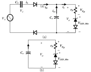
The conduction (Vf>Vo) mode and non-conduction (Vf<Vo) mode of bridge rectifier is shown in fig. 2 (a), (b) respectively. (a) (a) s
v
Co VLED_Min + ov
iD io rD ico + VrD + CS iS cv
Co + ov
VLED_Min + VrD + rD (b)(a) Conduction mode (b) Non-Conduction mode
Fig. 2. Modes of series capacitor type LED driver circuit
Fig. 3 shows the waveform behavior of the series capacitor LED driver circuit. When the threshold voltage of LED is greater than the input voltage of full-bridge diode, at that moment the diode current is blocked, as shown as M0 and M2. When the threshold voltage of LED is smaller than the input voltage of full-bridge diode, it conducts, shown as M1 and M3. M0 M1 M2 M3 M0 vf -vf vs vc vo c) a) b) 0 1 2
Fig. 3. Waveforms of series capacitor type LED driver
The equivalent circuit of conduction and non-conduction mode is shown in fig. 2 (a) and (b) respectively. During the conduction mode the electrolytic capacitor operates in charge and discharge cycles. During non-conduction mode, the capacitor discharge through the LED load. During conduction mode (a),
)
sin( t
V
V
V
V
s
c
f
(1))
cos(
)
sin(
)
(
c
v
t
dt
t
dv
c
dt
dv
c
t
i
s m m s c s s
(2)As rD is assumed to be zero, at that moment the bridge
diode and the voltage source is assumed to be ideal when, during one cycle of the AC power supply each equivalent circuit is shown in fig. 2 (a),
The current bridge diode conduction interval (12) is determined from the relationship between the input and the voltage drop of the LED in the equations (3)
) ( sin 2 1 1 1 Vm VLEDrate T (3)
At that time, the absolute value of the input current is equal to LED output current at an average of one cycle,
T s s m ratec
V
t
dt
T
dt
t
i
T
I
0 2 1)
cos(
1
)
(
1
(4)The equation to design the current limiting capacitor is given by ra te m s s
I
dt
t
V
C
c
2 1)
cos(
2
rate LEDrate mI
V
V
2
2
2
2
2.2 Proposed capacitor type LED driver
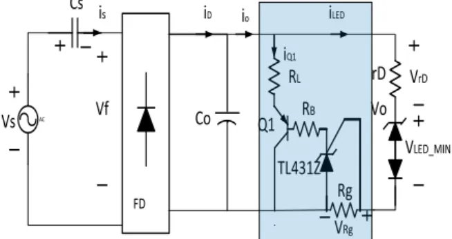
In the proposed simple LED driver, the existing circuit is further advanced by adding the current controlling device TL431Z, by which the reliable current control is possible in the designed circuit.
In the proposed circuit, the current regulating IC (TL431Z) is inserted between the capacitor filter and the LED light. The main function of this regulating IC is to control the flow of the current in the circuit as the specific design. In the given design, the maximum current output rating is 700[mA]. When the current through LED light exceeds 700[mA], the regulating IC, sensed the exceeding current and switched ON the IC and the current is sharing between IC itself and the LED light. Thus the IC continuously, monitors the regulating current in the circuit and provides the reliable protection. In the proposed simple LED driver, the existing circuit is further advanced by adding the current controlling device TL431Z, by which the reliable current control is possible in the designed circuit shown in fig. 4. AC FD Cs Vs Co RL RB Rg rD VLED_MIN Q1 TL431Z VRg VrD is iD io iLED Vf Vo iQ1
Fig. 4. Proposed simple LED driver circuit
LED current control is possible by using a small low current control device TL431Z by adding in the existing circuit. LED drive circuit consists of the series capacitor,
diode bridge, filter capacitor and LED series configuration as a load. Fig. 5 shows the relationship between the forward current and the forward voltage of the LED module used in this paper.
For representing the voltage, ideal diode forward voltage source and a dynamic resistance rD represents the equivalent
circuit. Dynamic resistance rD can be obtained by the
following equation. g D
n
R
I
V
r
*
)
(
(5) Where,n: Number of LED modules in series; Rg: : Current measuring resistor
Fig. 5.V-I curve of LUW H9GP module (Osram) In fig. 6, output current i0 can be expressed as the sum
of LED current( I LED ) and Q1 (IQ1).
LED Q
I
I
I
0
1
(6) IQ1 can be obtained by using equation 7.s o o D LEDMIN s
sc
I
I
r
V
V
(
*
)
(7) The output current-limiting resistor (RL) can becalculated by the equation (8)
max 0 Q L
I
V
R
(8) The current flow is shown in a small low-cost LED drive circuit of figure 6, where the maximum loss is in the Q1 of current (IQ1). AC FD Cs Vs Co RL RB Rg LED Q1 TL431Z VRg is iD io iLED Vf Vo iQ1 ILED LossFig. 6. Concept of current flow in a small simple LED drive
3. The Simulation and Experimental Results
In this section, To verify the feasibility of the proposed simple LED driver, a simulation circuit using PSIM was configured as shown in Fig. 7.
3.1 Simulation Results
(a) Schematic diagram by PSIM
(b) Result waveforms by PSIM
Fig. 7. Schematic diagram and layout of the proposed circuit by PSIM
3.2 Experimental Results
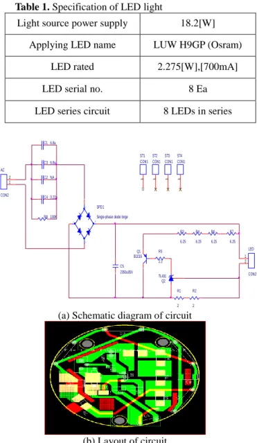
LUW H9GP (Osram)LED light is used for the experiment and the specification details are provided on table 1.
Table 1. Specification of LED light
Light source power supply 18.2[W]
Applying LED name LUW H9GP (Osram)
LED rated 2.275[W],[700mA]
LED serial no. 8 Ea
LED series circuit 8 LEDs in series
AC CON2 1 2 C3 6.8u + -~ ~ SPD1 Single-phase diode brige
R6 6.25 R7 6.25 R8 100K C5 2350u35V LED CON2 1 2 C1 6.8u C4 0.22u C2 NA ST3 CON1 1 ST2 CON1 1 ST1 CON1 1 ST4 CON1 1 Q2 TL431 R1 2 R2 2 R3 6.25 R4 6.25 Q1 B1016 R5 2.2
(a) Schematic diagram of circuit
(b) Layout of circuit
Fig. 8. Schematic diagram and layout of the circuit by
capture
The LED driver’s PCB with detail parts as shown in the fig. 9 , which maximum power is 2[W]. The specification of the LED light source is 150[mA], 12[V].
Fig. 9. PCB for simple LED driver
When the supply voltage is applied, the current flows in the circuit normally up to LEDs specified design. When the voltage is increased in the circuit, the current also gradually
increases. Fig. 10 shows the waveform during applying the voltage, 170Vrms (When Vsupply = 170 Vrms, ILED= 688mA,
IQ = 0). In fig. 11, As current in the circuit increases due to various reasons like increase in voltage or increase in temperature, the current also increase gradually,
When the current exceeds the designed value i.e. more than 700[mA], the current measuring register senses the increased current in the circuit and turn ON the device TL431Z. After TL431Z is turned ON, the surplus current i.e. more than 700[mA], share between TL431Z and LED lightsource, as shown in fig. 11 and fig. 12 respectively.
Fig.10. When Input Voltage is 170 Vrms, ILED = 688mA
and IQ = 0
Fig.11. When Input Voltage is 194 Vrms, ILED = 703mA and
IQ = 20%
Fig.12. When supply voltage Vs=233 Vrms, ILED =
710mA and, IQ= 45% ON
4. Conclusion
In this paper, TL431Z is introduced as the main device for current controlling. The specification of the LED load is 26[V], 700[mA]. When the current exceeds the rated current of the load, the current controller devices (TL431Z) senses the increased current in the circuit and turns it ON and shares the excess current through the device itself and the LED load. The device TL431Z continuously monitors the whole system. Thus current control device (TL431Z) makes the circuit more reliable, longevity as well as increase the luminous efficacy of the LED light.
The proposed LED driver is successfully developed with some positive expectations:
Circuit configuration is small and efficient so it is cost-effective. Uses a fraction of the power < 20[W] compared to traditional light. -Greater Energy-Efficiency - Lower Energy Costs. Since configuration is small, maintenance cost is also low. Wide range of applicable area due to compactness in size.
References
[1] W. Y. Han , H. S. Park,“Half-Bridge LLC Series Resonant Converter for driving LED Lamp”, The Korea Academia-Industrial Cooperation Societ, vol.11, no,11, pp.4483-4488, Nov 2010
[2] M. I. Heo, W. J. Yoo,“A Study on the activation of fusion technology through LED lighting industry”, The Korea Institute of illuminating and Electrical Installation Engineers vol.26, no.26, pp.1-5 1229-4691, Apr 2012
[3] Y. Hu and M. M. Jovanovic, “A New Current-Balancing Method for Paralleled LED Strings,” IEEE Applied Power Electronics Conference and Exposition(APEC), pp. 705-712, March, 2011.
[4] H. Mu, G. Li and J. Liu, “A High Precision Constant Current Source Applied in LED Driver,” Symposium on Photonics and Optoelectronics, pp. 1-4, May. 2011.
[5] Y. Hu and M. M. Jovanovic, “LED Driver with Self-Adaptive Drive Voltage,” IEEE Transactions on Power Electronics, vol. 23, no. 6, pp. 3116-3125, Nov. 2008.
[6] S. J. Yun, T. J. Oh, A. R. Cho, S. R. Ki, I. C. Hang, “Design of an Active Current Regulator for LED Driver IC”, The Korea Institute of Electrical Engineers, vol.61, no.4, pp.612-616 , Apr 2012
[7] H, S, Yoo, “Design of a high-power-factor LED driver with constant current regulation”, Seoul: Graduate School, Korea University, 2013
[8] Y. G. Jeong, S. I. Lee, J. K. Yang, D. H. Park “Analysis of Constant Current the LED Driving Circuit according to the Frequency characterization” The Korea Institute of Electrical Engineers, vol.2010 no.11, pp.120-120 , 2010 [9] H. Mu, G. Li and J. Liu, “A High Precision Constant
Current Source Applied in LED Driver,” Symposium on Photonics and Optoelectronics, pp. 1-4, May. 2011.
Seong-Mi Park received her B.S., M.S.,
and Ph.D. in Electronics and Computer Engineering from Chonnam National University, Gwangju, Korea, in 1986, 2001 and 2011, respectively. From 2004 to 2006, she was a Visiting Professor with the Department of Computer Engineering, Chonnam National University. Since 2013, she has been an Assistant Professor with the Department of Mechatronics Engineering, Korea Lift College, Geochang, Korea. Her current research interests include motor control, mechatronics and micro-machine automation.
Sung-Geun Songwas born in Gwangju, Korea. He received his B.S., M.S., and Ph.D. in Electrical Engineering from Chonnam National University, Gwangju, Korea, in 1998, 2000 and 2007, respectively. From 2001 to 2004, he was a Research Scientist at PROCOM system, Ltd., Korea. From 2004 to 2005, he was a Research Scientist at SEO ELECTRONICS CO., LTD., Korea. Since 2008, he has been with for KETI (Korea Electronics Technology Institute), where he is currently working at the Gwangju Regional Headquarters. His current research interests include power electronics, motor drives, digital signal processing, tractions, and their control systems.
Sang-Hun Lee was born in Busan,
Korea, in 1974. He received his B.S and M.S. degrees in Electrical Engineering from KyungSung University, Busan, Korea, in 2000, 2002, respectively. He
received his Ph.D degrees in
Mechatronics Engineering from Pusan National University, Busan, Korea, in 2006. He worked a Junior Researcher of Technology& Researcher at KTE, from 2002 to 2004, He has been with Kyungsung University, Busan, Korea, as a Researcher in the Advanced Electric Machinery & Electronics Center since 2006. Since 2014, he has been a Assistant Professor with the Department of Electrical Automatic Engineering, Yeungnam College of Science & Technology, Daegu, Korea. His major research field is Electrical Motor Drive with Power Electronics.