GEOTECHNICAL DESIGNS OF THE SHIP IMPACT PROTECTION SYSTEM FOR
INCHEON BRIDGE
SUNG-MIN CHOi), SEUNG-TAK OH ii), SANG-IL PARK iii), AND SUNG-HWAN KIM iv) ABSTRACT
The Incheon Bridge, which was opened to the traffic in October 2009, is an 18.4 km long sea-crossing bridge connecting the Incheon International Airport with the expressway networks around the Seoul metropolitan area by way of Songdo District of Incheon City. This bridge is an integration of several special featured bridges and the major part of the bridge consists of cable-stayed spans. This marine cable-stayed bridge has a main span of 800 m wide to cross the vessel navigation channel in and out of the Incheon Port. In waterways where ship collision is anticipated, bridges shall be designed to resist ship impact forces, and/or, adequately protected by ship impact protection (SIP) systems. For the Incheon Bridge, large diameter circular dolphins as SIP were made at 44 locations of the both side of the main span around the piers of the cable-stayed bridge span. This world’s largest dolphin-type SIP system protects the bridge against the collision with 100,000 DWT tanker navigating the channel with speed of 10 knots. Diameter of the dolphin is up to 25 m. Vessel collision risk was assessed by probability based analysis with AASHTO Method-II. The annual frequency of bridge collapse through the risk analysis for 71,370 cases of the impact scenario was less than 0.5×10⁻⁴ and satisfies design requirements. The dolphin is the circular sheet pile
structure filled with crushed rock and closed at the top with a robust concrete cap. The structural design was performed with numerical analyses of which constitutional model was verified by the physical model experiment using the geo-centrifugal testing equipment. 3D non-linear finite element models were used to analyze the structural response and energy-dissipating capability of dolphins which were deeply embedded in the seabed. The dolphin structure secures external stability and internal stability for ordinary loads such as wave and current pressure. Considering failure mechanism, stability assessment was performed for the strength limit state and service limit state of the dolphins. The friction angle of the crushed stone as a filling material was reduced to 38° considering the possibility of contracting behavior as the impact.
Key Words : Ship Impact Protection, Incheon Bridge, Annual Frequency of Bridge Collapse, Vessel Collision 1 INTRODUCTION
1.1 Incheon Bridge
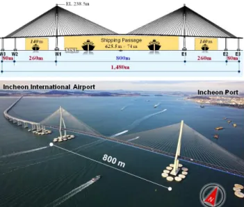
The Incheon Bridge, the longest bridge of Korea, is an 18.4 km long sea-crossing bridge connecting the Incheon International Airport with the expressway networks around the Seoul metropolitan area by way of New Songdo City, a new developing International Free Economic Zone (IFEZ). As a world-famous hub airport, the Incheon International Airport is the world’s 2nd and 10th busiest airport in terms of international passengers and cargo handling, respectively. This bridge is an integration of several special featured bridges and the major part of the bridge consists of cable-stayed spans. This marine cable-stayed bridge has a main span of 800 m wide to cross the vessel navigation channel in and
out of the Incheon Port. Figure 1. Location and route map of the Incheon Bridge
i) Principal Research Engineer of Research Institute, Korea Expressway Corporation (KEC), South Korea
ii) Ph.D. candidate, Director General of Construction Management Division, Korea Expressway Corporation, South Korea
ii) Head of Research Institute, Korea Expressway Corporation, South Korea
Figure 2. Cable stayed bridge across the navigation channel in and out of the Incheon Port
Constructions were fulfilled from 1 July 2005 to 19 October 2009 (52 months). Total cost of the project was about 2.1 billion USD. The competent authority of the Incheon Bridge construction project was Korea Expressway Corporation (KEC), a government corporation in charge of planning, construction, and management of national expressways under the commission of the Ministry of Land, Transport, and Maritime affairs (MLTM).
1.2 Ship Impact Protections of the Bridge
A bridge across the waterway can be merely an obstacle from the viewpoint of ship navigations. So, in waterways where ship collision is anticipated, bridges shall be designed to resist ship impact forces, and/or, adequately protected by a kind of ship impact protection (SIP) systems including dolphins, berms, islands, fenders, or other sacrificial devices (AASHTO, 1997; 2007). Typical ship impact protection systems for the bridge are shown in Figure 3.
Figure 3. Various types of the SIP system
The curved shape of the Incheon Bridge route shown in Figure 1 and Figure 2 was inevitable to accept the government request to locate the bridge 3 km away to the south from the Incheon Port for the safety of vessels passing under the bridge. The competent maritime authority also demanded a protective facility around the piers to resist against collision of very large vessel (up to 100,000 DWT) with the 10 knots speed. 2 DESIGN OF SHIP IMPACT PROTECTIONS 2.1 Specifications
The Incheon Bridge was designed to comply with AASHTO LRFD (load & resistance factor design) Bridge Design Specification according to the Project Performance Requirement (PPR) by the agreement between the government and the concessionaire. For the SIP design, additional several specifications were adopted. They are AASHTO’s Guide Specification and Commentary for Vessel Collision Design of Highway Bridges, US Army Corps of Engineers’ Manual: Design of Sheet Pile Cellular Structures, British Standard: 6349 Maritime Structures, and Korean Design Criteria for the Port and Fishery Harbor. In compliance with the agreements for the project and related specifications, SIP system should protect the Incheon Bridge against the collision with 100,000 DWT tanker navigating the channel with speed of 10 knots. The 100,000DWT design ship combined with the AASHTO formula for the impact velocity that is given in the PPR for design of the impact protection is used for design of the protection in the primary impact direction parallel with the navigational channel (Cho, 2009; Cho et al., 2009). 2.2 Type, Materials and Behavior of the SIP
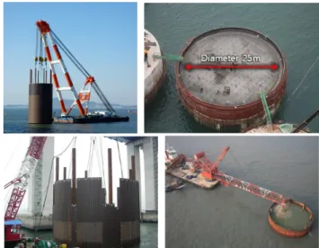
Dolphin type SIP which consists of steel sheet piled wall and infilling aggregates were selected for this project. Large diameter circular dolphins were made at 44 locations of the both side of the main span around the piers of the cable-stayed bridge portion. Figure 4 shows the alignment of dolphins. Diameter of the dolphin is up to 25 m.
This dolphin is a kind of circular cell structure filled with aggregates. It has been used for harbor facilities and cofferdam constructions. Figure 5 presents the previous cases of this structure as cofferdams.
Figure 5. Cell structures for the cofferdam construction Cross-section and materials of the SIP structure for the Incheon Bridge are described in Figure 6. Scale of the SIP can be roughly guessed from the maquette of SIP dolphins enclosing the pylon’s pile cap in the Figure 6.
Figure 6. Cross-section, plan of the SIP structure
Figure 7. Dolphin’s deformation due to the ship collision The dolphin as SIP for the Incheon Bridge is the circular sheet pile structure filled with crushed rock and closed at the top with a robust concrete cap. Cap consists of segmental concrete facing, top slab concrete, and fender. So, the dolphin structure formed shall secure external stability and internal stability for ordinary loads such as wave and current pressure. Schematic deformation characteristics of the dolphin structure which was penetrated into the seabed ground are depicted in Figure 7. SIPs are sacrificial structures
that will be partly or fully destroyed in the event of a severe impact. The stopping capability of the dolphins involves huge deformations, non-linear soil behavior and dynamic soil-structure interaction. Considering failure mechanism, stability assessment was performed for the strength limit state and service limit state.
Circular wall of the dolphin cell was made of straight web type steel sheet pile (thickness 12.7 mm, length 500 mm). Steel of the sheet pile was classified as S355GP of EN10248. Its yield strength (fy) and tensile
strength (fu) were 355 Mpa and 480 Mpa respectively.
Minimum interlocking strength was 5,500 kN/m and minimum tensile strain was 17 %.
Figure 8. Dimension of the straight web sheet pile
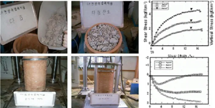
Gravels and crushed stones were decided as in-filling material. Diameter of the filling material was up to 200 mm (Figure 9). Brief results of large scale tri-axial compression test for the crushed stone are summarized in Figure 10. The friction angle of the crushed stone as a filling material was reduced to 38° considering the possibility of contracting behavior as the impact (Cho, 2009).
Figure 9. Grain size distribution of the filling material
Figure 10. Large scale tri-axial compression test of the crushed stone as filling material
2.3 Subsurface Conditions and Geotechnical Considerations to the Design
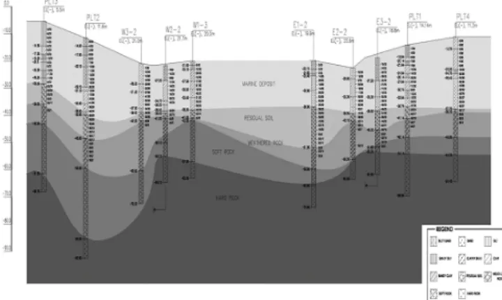
Geotechnical investigations including in-situ tests were performed along the bridge alignment to find the engineering characteristics of the seabed soils. Ground profile at the SIP area may be summarized as from the surface: marine deposits (clay, silt and sand; thickness 15-26 m), residual soils (sand; thickness is up to 17 m), weathered rock (RQD is 0 to 20 %; thickness is up to 20 m), and soft rock (bedrock). See Figure 11.
Figure 11. Ground profile at the SIP area along the bridge route
Sheet pile was penetrated into the residual sand soil layer to secure the stability of the structure and to resist against the collision impact (Figure 6). Clay layers at the upper layer of the seabed have relatively low shear strength. The silt layers in the marine deposits are non-plastic, or low-plastic. N blows of the standard penetration test of the sandy layer were measured as from 0 to 40. The residual layers consist of silty sand and small amount of rock fragments. N blows of the standard penetration test of this layer range from 20 to 100. Due to the highly variable soil conditions (variation from borehole to borehole) all boreholes in the vicinity of the SIPs were considered in order to produce representative design profiles for the individual SIP structures.
A total of nine different design profiles were developed for the design of the 44 Ship Impact structures for both drained and undrained conditions The design profiles were developed based on the available field information of SPT testing in soils and pressuremeter testing in the rock. Field tests were supplemented by laboratory tests, 10 triaxial UU test and 3 triaxial CU tests. Deformation parameters were inferred from well winnowed international empirical correlation rules based on the classification tests (Lars Hauge et al., 2009).
Considering the inherent nature of the ship impact phenomenon, the un-drained shear strength of the seabed soil is important. Based on two consolidated un-drained tri-axial tests on sandy silt it was concluded
that the soil would exhibit negative pore pressure development (equivalent to dilation in drained conditions). Hence, these deposits were conservatively assumed to be drained in the design. In general the choice of soil profiles entailed a balanced evaluation of the most onerous combinations in terms of bearing capacity, side resistance and settlements. Thus the characteristic soil profiles are associated with choices of maximum possible amount of clay in particular with depth. In order to function according to the design much attention was given to the fill inside the dolphins and to the associated water level fluctuations in the fill material. Thus, the interaction between the vertical effective stress and the wall friction was studied in detail. Both analytical and numerical models were used for the analysis of the different limit states, strength limit state, service limit state and extreme limit states (Lars Hauge et al., 2009).
Geotechnical stability analysis for this structure was divided into 2 groups. The first is an external stability evaluation against the sliding, overturning, bearing capacity, and settlement. The other is an internal stability analysis for the seam failure (interlock fail) and the shear failure of filling gravel.
2.4 Geotechnical Modeling and Analysis
Numerical modeling by FEM scheme was used to find the detailed behavior of the dolphin structure. And geo-centrifugal experiments using reduced structure in the laboratory were also carried out to verify the numerical model. The centrifugal tests with simplified geometry conditions presented the insight in the relevant failure modes, the soil-structure-water interaction in the event of a real time modeled impact, and the necessary backbone data for verification of the numerical 3D modeling with actual conditions.
Thanks to this centrifuge test, the global quasi-static force response of the dolphins for direct comparison with the response predicted by 3D FEM analysis was obtained. The global response in dynamic impact scenarios for comparison with the quasi-static experimental results was also found. And it was possible to find the local force-indentation relationship for deep impact causing local indentation and even damage of the sheet piles (Kim et al., 2007).
The physical model tests considered the behavior of a single circular dolphin with very simplified albeit realistic soil stratification using homogeneous layers. Thus, emphasis was placed on achieving reproducible testing conditions allowing high credibility of output and well defined conditions for comparison with the numerical 3D calculations. A fine grained Baskarp sand (grain size 0.15 mm) was used in this centrifuge model. 7 quasi-static and 11 dynamic model tests for 2 different prototype dolphins were carried out. Figure 12 shows the centrifuge model setup and the equipment.
Figure 12. The centrifugal setup using a reduced model
Figure 13. FEA mesh: displacement contour before the impact (left) and right after the impact (right)
Designs were performed with numerical analyses of which constitutional model was verified by the physical model experiment using the geo-centrifugal testing equipment. The 3D non-linear FE models were used to analyze the structural response and energy-dissipating capability of dolphins which were deeply embedded in the seabed. As a result of comparison between numerical analyses and model tests, a very convincing correspondence was observed along the entire displacement range and it seems that assessing dolphin behavior by FEM model give more conservative results than actual dynamic behavior (Figure 14).
Figure 14. Comparison of the FE analysis and the test In order to be able to treat the large number of design situations and soil profiles the bearing capacity calculations were also checked using 2D FEA program. It was evaluated that this would provide a conservative estimate compared with the much more cumbersome and time consuming 3D analysis. However, for the ship impact it was considered imperative to be able to quantify and qualify the behavior by 3D dynamic analyses using 3D FEA program (Figure 15).
Figure 15. A result of 2D FE analysis
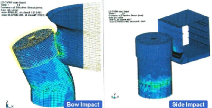
Dolphin structure itself was also evaluated during the ship impact according to the types of the vessel impact. Figure 16 shows the example of dolphin displacement at the impact by the ship bow and ship side respectively.
Figure 16. Displacement shape of the dolphin 3 RISK ANALYSIS
Design process flow of the SIP structure is described in Figure 17. Total design was divided into 3 parts: traffic analysis, risk analysis, and structural (geotechnical) analysis.
Figure 17. Design procedure of the SIP
Vessel collision risk was assessed by probability based analysis with AASHTO Method-II. Annual frequency of bridge collapse (AF) was computed for each bridge component and vessel classification. The AF can be taken as multiplication value of the annual
number of vessel, the probability of vessel aberrancy, the geometric probability of a collision between an aberrant vessel and a bridge pier, and the probability of bridge collapse due to a collision with an aberrant vessel. For the design of the Incheon Bridge as a critical structure, the maximum AF shall be less than 0.0001. The computed AF of the Incheon Bridge through the risk analysis for 71,370 cases of the impact scenario was less than 0.5×10⁻⁴ and satisfies design requirements
(Figure 18).
Figure 18. Calculated annual frequency of collapse after installation of the SIP dolphins
4 CONCLUSION
The marine cable-stayed bridge span of the Incheon Bridge has a main span of 800 m wide to cross the vessel navigation channel in and out of the Incheon Port. Large diameter circular cell type dolphin structures as ship impact protections were made at 44 locations of the both side of the main span around the piers of the cable-stayed bridge span. This world’s largest dolphin-type SIP system protects the bridge against the collision with 100,000 DWT-vessel.
Vessel collision risk was assessed by probability based analysis with AASHTO Method-II. The annual frequency of bridge collapse through the risk analysis for the impact scenario satisfies design requirements. The design of the structure was performed with numerical analyses of which constitutional model was verified by the physical model experiment using the geo-centrifugal testing equipment. 3D non-linear finite element models were used to analyze the structural
response and energy-dissipating capability of dolphins which were deeply embedded in the seabed. The dolphin structure secures external stability and internal stability for ordinary loads such as wave and current pressure. Considering failure mechanism, stability assessment was performed for the strength limit state and service limit state of the dolphins.
Figure 18. Constructions of the SIP dolphins REFERENCES
1) AASHTO (1994), Guide Specification and Commentary for Vessel Collision Design of Highway Bridges
2) AASHTO (2007), LRFD Bridge Design Specification, 4th Edition, American Association of State Highway and Transportation Officials, Washington DC.
3) Cho, Sung-Min (2009), “Geotechnical Engineering Progress with the Incheon Bridge Project”, Proceedings of the
International Symposium on Urban Geotechnics: Development and Future of Incheon Metropolitan City,
Korean Geotechnical Society
4) Cho, Sung-Min and Yoo, Cungsik (2009), “Incheon Bridge Construction - Geotechnical Challenges”, ISSMGE Bulletin, International Society for Soil Mechanics and Geotechnical Engineering, Vol.3, Issue 2, pp.16-24
5) Cho, Sung-Min et al., (2009), “Incheon Bridge: Facts and the state of the art”, Proceedings of the International
Commemorative Symposium for the Incheon Bridge, Incheon,
Korea, pp.18-28
6) Kim, Byung-Sun et al., (2009), “Construction of the ship-impact protective dolphin in Incheon Bridge project”,
Proceedings of the International Commemorative Symposium for the Incheon Bridge, Incheon, Korea, pp.564-571
7) Kim, J.H., Kim, Z.C., Shin, H.Y., Cho, S.M., Schaminee, P.E.L, and Gluver, H. (2007), “Centrifuge testing for the design of ship impact protection of Incheon Bridge Project”,
Proceedings of the 16th International Offshore and Polar Engineering Conference, Lisbon, Portugal, pp.1613-1618.
8) Lars Hauge, Henrik Gluver, Oliver Kübler, Jørgen Steenfelt, Jens-Erik Jepsen, and Erik Yding Andersen (2009), “Ship Impact Protection Design for the Incheon Bridge”,
Proceedings of International Commemorative Symposium for the Incheon Bridge, Incheon, Korea, pp. 466-487