Current Status of the LMR Core Thermal Hydraulic Design and Analysis Methodology
for the KALIMER Development
Y. G. Kim, H. Song, Y. I. Kim Korea Atomic Energy Research Institute 150 Dukjin-dong, Youseong, Daejeon 305-353, Korea, Phone: 042-868-2966, Fax: 042-861-9605, E-mail: [email protected]
1. Introduction
KALIMER, a pool-type sodium cooled reactor with a metallic fueled core, has been developed at KAERI. Various core concepts were designed and analyzed in the core design technology development group. Recently KALIMER-600 breakeven core of a single enrichment which uses no blanket has been studied. In this context, the K-CORE system, an integrated system for the KALIMER core design and analysis, has been developed to provide major data links among the principal core nuclear and thermal hydraulic design modules. This paper describes the current status of the core thermal hydraulic design and analysis methodology for the KALIMER core development.
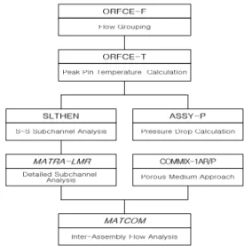
2. Core Thermal Hydraulic Conceptual Design Tools The overall tools for the core thermal hydraulic design and analysis, which is used in the KALIMER core conceptual design, are summarized as shown in the figure 1, i.e., flow grouping and peak pin temperature calculation, pressure drop calculation, steady state and detailed subchannel analyses, and inter-assembly flow analysis. These tools are expected to be extensively used for a basic data production during the conceptual design phase [1]. 2.1 Core Flow Grouping
Coolant flow controls, i.e., orificing flow restrictions, are located at the inlet receptacles into which the assemblies are inserted at the nosepiece ends, or at the lower part of the fuel assembly just after the inlet holes. Sodium coolant flow has to be supplied to the assemblies based on the peak pin linear heat generation rate to ensure the structural integrity of the fuel, claddings and ducts. Small flow control is not expected with these controls and thus the flow groups are limited in their numbers.
In the conceptual design phase, the reflector, shield and IVS assemblies are not considered for flow grouping because their flow rates are very small and their powers do not change significantly throughout their lifetime to complicate their detailed orificing. The flow grouping for these regions will be expanded later with more elaborated
heating calculations, coupled neutron and gamma heating calculations.
Figure 1. KALIMR core thermal hydraulic analysis tools 2.2 Peak Pin Temperature Calculation
The temperatures which influence the design conditions have to be checked with the limit values to insure the safe operation of the reactor. For example, the equalized cladding midwall temperature at a normal operation is limited to 650℃ for HT9M to ensure the structural integrity of the cladding materials. The peak fuel surface temperature is limited to 700℃ to avoid a liquefaction of a low melting temperature alloy formed by an inter diffusion of the cladding iron and fuel uranium and TRU. Liquefaction greatly accelerates the cladding internal wastage rates and shortens the pin lifetime. Hot channel factors are introduced in the temperature predictions to account for the design, analysis, fabrication and operational uncertainties and variations. 2σ uncertainty factors based on CRBR analyses are employed in the KALIMER core thermal hydraulic conceptual design. 2.3 Pressure Drop Calculation
The pressure drop in the assembly of maximum coolant flow, and thus the core pressure drop have to be checked
Transactions of the Korean Nuclear Society Autumn Meeting Busan, Korea, October 27-28, 2005
to see if they are within the allowable value range, once the flow grouping and peak pin temperature calculations were performed.
For the wire wrapped rod bundle assemblies, three developed models are used in the bundle pressure loss calculations, i.e., the Novendstern model, Chiu-Rohsenow-Todreas (CRT) model, and Cheng-Todreas (CT) model. For the other parts of the assembly, pressure drop calculation modules are set up using simple formulas of sudden/smoth expansion and contraction modeling.
In this conceptual design stage, the estimated core pressure drop is calculated with a 20 % uncertainty. But this estimation was done with a rough pressure drop modeling, and it is expected to have further improvements of pressure drop modeling.
2.4 Subchannel Analysis
The core wide coolant and fuel temperature profiles are efficiently calculated using the simplified energy equation mixing model and the subchannel analysis method, SLTHEN code, which is a multi-assembly, steady-state subchannel analysis code based on the above simplified energy equation mixing model [2]. The momentum coupling between coolant channels is indirectly taken into account using the enhanced eddy diffusivity and the swirl velocity ratio with the experimental modeling developed for the wire wrap spacing rod assemblies. This code provides temperature maps for all the pins in all the assemblies and thus facilitates core wide failure probability studies.
The detailed subchannel analysis is performed with the MATRA-LMR code [3] which is developed for liquid metal reactors based on COBRA-IV-I and MATRA [4]. MATRA-LMR solves the mass, axial and transverse momentum, and energy equations.
3. Inter-Assembly Flow Analysis
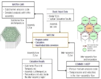
In the LMR core, flow redistribution can be occurred in the inter-assembly region of the core. The hotter counter flow from the upper center region of the LMR core may have a significant effect on the thermo-mechanical integrity of the duct wall. A combined method was developed using the subchannel analysis and the porous media approach. The objective of the method is to obtain the temperatures of a subassembly duct walls, strongly influenced by the inter-assembly flow redistribution in the core. The procedure consists of the subassembly calculation and the cylindrically modeling core calculation as shown in the figure 2.
Figure 2. MATCOM code structure for the inter-assembly flow analysis
4. Summary and Further Studies
The current status of the core thermal hydraulic design and analysis methodology for the KALIMER development is summarized in this paper. The overall conceptual design procedure consists of flow grouping, peak pin temperature calculation, steady state and detailed subchannel analysis, and the inter-assembly flow analysis. The detailed subchannel analysis code MATRA-LMR and the inter-assembly flow analysis code MATCOM will be improved and verified for the core conceptual design and evaluation.
Acknowledgement
This study was supported by the Korean Ministry of Science & Technology through its National Nuclear Technology Program.
REFERENCES
[1] Y. G. Kim et al., Thermal Hydraulic Analysis of the KALIMER-600 Single Enrichment Core, ICAPP’05, Seoul, Korea, 2005.
[2] W. S Yang, An LMR Core Thermal Hydraulics Code Based on the ENERGY Model, Journal of KNS, 29, pp.406-416, 1997.
[3] W. S. Kim et al., A Subchannel Analysis Code MATRA-LMR for Wire-Wrapped LMR Subassembly, Annals of Nuclear Energy, 29, pp.303-321 (2002). [4] Y. J. Yoo and D. H. Hwang, Development of
Subchannel Analysis Code MATRA α version, Proc. of KNS Autumn Meeting, Taegu, Korea (1997).