Sensitivity Study of Peak Cladding Temperature on the Operation Parameters for the 3-Pin
Fuel Test Loop
S. K. Park,D. Y. Chi, B. S. Shim, K. N. Park, S. H. Ahn, J. M. Lee, C. Y. Lee Korea Atomic Energy Research Institute, P.O.B. 105, Yuseong-ku, Daejeon Korea 305-600
[email protected] 1. Introduction
3-pin fuel test loop (FTL) is under development in HANARO (High-flux Advanced Neutron Application Reactor). It is an experimental facility that provides fuel irradiation and burn up tests under the operation conditions of commercial PWR and CANDU plants. This paper deals with the sensitivity study of peak cladding temperature on the operation parameters for loss of coolant accident of the 3-pin fuel test loop.
2. Methods and Results 2.1 Modeling of the Fuel Test Loop
The fuel test loop consists of an in-pile test section (IPS) and an out-pile system (OPS). The IPS states a pressure vessel and the connecting pipes between the pressure vessel and the OPS. The OPS is a processing and control system for sustaining proper test conditions. The pressure vessel of the IPS will be installed in the IR1 hole of the HANARO core and the OPS in the room 1. The OPS is categorized into main cooling water system, emergency cooling water system, and letdown, make-up and purification system etc. The emergency cooling water system provides a passive cooling capability for test fuels subsequent to anticipated operational occurrences (AOO) and design basis accidents (DBA).
MARS computer code has been used for the prediction of peak cladding temperature for loss of coolant accident [1, 2, 3]. The main cooling water system including the IPS and the emergency cooling water system were modeled with the MARS code.
The fuel zone of the pressure vessel was modeled with a pipe having 7 sub-volumes and test fuels were modeled as a heat structure component having 7 axial nodes and 11 radial meshes. The fuels for PWR test mode are 700mm long and the diameters are 9.5mm. The inner and outer vessel, flow divider, and fuel transport legs of the IPS were also modeled as a heat structure component because of gamma heating.
The fuel test loop has two protection systems. One is HANARO protection system which provides fast scram from the trip parameters such as the high flow, low flow, high pressure, low pressure and high temperature of the IPS. The other is FTL protection system which isolates
the IPS from the OPS and injects emergency cooling water into the IPS from the trip parameters such as the high flow, low-low flow, low-low pressure, and high-high temperature of the IPS.
2.2 Modeling of LOCAs
It was assumed that the pipe breaks occurred at the cold and hot legs in the room 1 and the HANARO pool. The small and the large break loss of coolant accidents were investigated. The small break loss of coolant accident (SBLOCA) was investigated for various break areas to find maximum peak cladding temperature. The large break loss of coolant accident (LBLOCA) was also calculated for the 4 discharge coefficients of 0.1, 0.33, 0.67, and 1.0. The break time was assumed 0.01 seconds. Henry-Fauske model was used for critical flow calculation at break location.
2.3 Results
The preliminary calculation of the small and large break LOCAs indicates that the small break of cold leg is the most severe accident [4, 5, 6, 7]. Therefore the sensitivity of peak cladding temperature on the operation parameters of the PWR fuel test mode has been investigated for the small break of cold legs in the room 1 and the HANARO pool.
The operation parameters and ranges investigated in the present study are described in Table 1. The investigated parameters of flow properties are the thermal power of test fuel and the flow rate, coolant temperature, and coolant pressure of the IPS. The stroke times of loop isolation vales (LIVs), safety injection valves (SIVs), and depressurization valves (DPVs) are also investigated.
The reference values in Table 1 are the design operation conditions for PWR fuel test mode. The operation ranges are determined by considering the measurement uncertainties of the flow properties and the random discrepancies between the design and actual operations.
Table 1 Parameters and ranges for sensitivity analysis
param-
eters power (kW) flow (kg/s) temp. press. (MPa)
Transactions of the Korean Nuclear Society Autumn Meeting Busan, Korea, October 27-28, 2005
(℃) reference value 63.0 1.6 300.3 15.6 ranges ±5% ±5% ±2% ±2% cold leg LIVs (s) hot leg LIVs (s) cold Leg SIVs (s) hot leg SIVs (s) DPVs (s) 2.5 2.5 0.2 0.2 0.2 ±13% ±13% ±113% ±13% ±13%
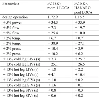
Table 2 is the results of the sensitivity of peak cladding temperature on the operation parameters. In case of the design operation maximum peak cladding temperatures are 1172.9K and 1116.5K for the LOCAs in the room 1 and the HANARO pool respectively.
The present investigation indicates that the effect of the stroke times of the safety injection valves and the depressurization valves on the peak cladding temperature is negligible. The increase of the test fuel power, the coolant temperature, and the stroke time of the cold leg loop isolation valve increases the maximum peak cladding temperatures. The peak cladding temperatures increase also with the decrease of the stroke time of the hot leg loop isolation valve. The effect of the stroke times of the loop isolation valves on the peak cladding temperature is greater for the HANARO pool LOCA than the room 1 LOCA. In the ranges investigated presently the maximum increase of the peak cladding temperature is approximate 34K in case of the increase of fuel power by 5%.
Table 2 Peak cladding temperatures in the various operation conditions
Parameters PCT (K),
room 1 LOCA PCT(K), HANARO
pool LOCA design operation 1172.9 1116.5 +5% power +34.3 +33.9 +5% flow -7.3 -19.7 -5% flow -25.4 -10.0 +2% temp. +6.7 +0.7 -2% temp. -38.9 -27.1 +2% press. -10.4 -3.9 -2% press. -10.2 +6.2
+13% cold leg LIVs (s) +7.3 +25.7
-13% cold leg LIVs (s) -25.1 -26.5
+13% hot leg LIVs (s) -1.8 -2.2
-13% hot leg LIVs (s) +4.1 +10.4
+13% cold leg SIVs (s) -1.0 +0.2
-13% cold leg SIVs (s) +1.6 -0.1
+13% hot leg SIVs (s) +0.8 -0.3
-13% hot leg SIVs (s) -0.6 +0.2
+13% DPVs (s) -0.2 -0.3
-13% DPVs (s) +0.3 +0.3
3. Conclusion
The peak cladding temperatures for the 3-pin fuel test loop are calculated in the various operation parameters. The results indicate that the peak cladding temperature increases with the increase of the test fuel power, the coolant temperature, and the stroke time of the cold leg loop isolation valve. The effect of the stroke times of the safety injection valves and the depressurization valves on the peak cladding temperature is negligible.
Acknowledgements
This wok was performed under the Nuclear R&D Program of the Ministry of Science and Technology of Korea.
References
[1] W.J. Lee, et. al., “Improved Features of MARS 1.4 and Verification,” KAERI/TR-1386/99, Korea Atomic Energy Research Institute, 1999.
[2] RELAP5/MOD3.3 Code Manual Volume IV: Models and Correlations, NUREG/CR-5535/Rev 1, 2001.
[3] MARS 2.1 Code Manual, Input Requirement, KAERI, 2002. [4] S. K. Park et. al., “Analysis of the LBLOCAs in the Room 1 for the 3-Pin Fuel Test Loop,” KAERI/TR-2861/2004, Korea Atomic Energy Research Institute, 2004.
[5] S. K. Park et. al., “Analysis of the SBLOCAs in the Room 1 for the 3-Pin Fuel Test Loop,” KAERI/TR-2830/2004, Korea Atomic Energy Research Institute, 2004.
[6] S. K. Park et. al., “Analysis of the LBLOCAs in the HANARO Pool for the 3-Pin Fuel Test Loop,” KAERI/TR-2867/2004, Korea Atomic Energy Research Institute, 2004. [7] S. K. Park et. al., “Analysis of the SBLOCAs in the HANARO Pool for the 3-Pin Fuel Test Loop,” KAERI/TR-2815/2004, Korea Atomic Energy Research Institute, 2004.