P2-78 / J.-H. Lim
• IMID 2009 DIGEST
Phone : +82-31-299-6562 , Email : [email protected]
Abstract
In this work we present a new type of line plasma source using an internal-type ICP operated at 2MHz with a ferrite module, describe the effect of ferrite module on the enhancement of the plasma properties and the uniformity, and compare to those obtained with 13.56MHz discharge. Also the electrical characteristics of the antenna line and the characteristics of the plasma uniformity were studied.
1. Introduction
These days, flexible display devices are being investigated by many researchers as the possible next generation displays and one of the important techniques for flexible display processing is the roll-to-roll plasma processing. [1-2] For the fabrication of flexible display devices by the roll-to-roll plasma processing, not only highly uniform plasma processing but also high processing rates are required to increase the throughput of the processing. Especially, when low temperature substrates such as plastic substrates are used for the roll-to-roll plasma processing, the high processing rate should be achieved at the temperature lower than 100°C. One of the methods to achieve high processing rates in addition to low temperature processing is to use high density plasma sources. In addition, for the application to the roll-to-roll processing, line-type high density plasma sources are required. In recent years, several research groups reported line-type high density plasma sources for the roll-to-roll processing of flexible substrates by using microwave plasma or capacitively coupled plasma with a very high frequency (VHF) higher than 13.56MHz.[3] Although relatively high quality films at high deposition rates and high etch processing rates could be obtained through the high density plasma sources generated by microwave plasmas and VHF plasmas, it is very hard
to obtain uniform plasmas over a meter-scale-width flexible substrate in the high frequency ranges due to the standing wave effect [4,5]
In this study, we present a new line-type high density plasma source composed of a line-type internal antenna for inductively coupled plasma (ICP) operated at 2MHz and a ferrite module installed on the antenna of the ICP source. Using the line-type internal antenna, electrical and plasma characteristics of the source were investigated as the possible application to large-width flexible substrate processing during the roll-to-roll processing and the characteristics of the source were compared with the source characteristics operated at 13.56MHz without a ferrite module.
2. Experimental
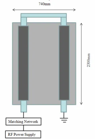
The experimental setup of the internal ICP system used in this study is schematically shown in Figure 1. The processing chamber has a rectangular shape with the size of 2,750mm × 2,350mm for the application of large-area FPD processing. The U-shaped, line-type, internal antenna with the size of 240mm × 2300mm was installed in the center of the processing chamber and a shield with the size of 740mm × 2300mm was also installed around the antenna to limit the plasma near the line-type antenna. The effective stationary substrate size, which was limited by the shield size, was also 740mm × 2300mm.
One-end of the U-shaped internal antenna was connected to an rf power generator through an L-type matching network while the other end was connected to the ground directly. Rf characteristics of 2MHz, 5kW (ENI NOVA) and 13.56MHz, 10kW (RFPP) were used for the antenna. The plasma characteristics of the source were measured using a Langmuir probe (Hiden Analytical Inc., ESP), and the electrical properties of the line-type, internal antenna were
Characteristics of Line-type Internal Inductively Coupled
Plasma Source for Flexible Display Processing
Jong Hyeuk Lim
1, Kyong Nam Kim
1, Gwang Ho Gweon
1, Seung Pyo
Hong
1, and Geun Young Yeom
1,21Department of Materials Science and Engineering, Sungkyunkwan University, Suwon, Kyunggi-do, 440-746, S. Korea
2The National Program for Tera-Level Nanodevice, Hawolgok-dong, Sungbuk-ku, Seoul, 136-791, S. Korea
P2-78 / J.-H. Lim
IMID 2009 DIGEST • measured using an impedance analyzer (MKS Inc.)
located between the matching box and the antenna.
Fig. 1. Schematic diagram of an internal ICP source with the ferrite module.
The characteristics of the plasma uniformity were investigated using a homemade, movable, electrostatic probe system consisting of four tips located 32cm below the antenna and 20cm above the substrate. The probe system, biased at -65 Volts, was scanned along the antenna line to measure the distribution of the two-dimensional, ion saturation current above the substrate. Using the U-shaped antenna system operated at 2MHz with a ferrite module and a gas mixture of Ar/O2 (7:3) at 40mTorr, a glass substrate covered with AZ1512 photoresist was etched and its etch depth was measured using a step profilometer (Alpha Step 500) to estimate the etch uniformity along the antenna line.
3. Results and discussion
Figure 2 shows the plasma density measured by a Langmuir probe (Hiden Inc.) as a function of delivered rf power of the line-type ICP source operated with 13.56MHz rf power and with 2MHz rf power (after installation of a ferrite module). As the
operating gas, 30mTorr~50mTorr Ar was used. As shown in Fig. 2, the plasma density was increased with the increase of rf power almost linearly for both rf powers of 13.56MHz and 2MHz (with the ferrite module). However, the source with the 2MHz rf power showed higher plasma density compared with the source with 13.56MHz rf power at the same rf power and, at 3500W, the source with the 2MHz rf power with the ferrite module showed the plasma density of about 4.0 × 10¹¹/cm3 at 50mTorr Ar gas.
Fig. 2. Plasma density measured by a Langmuir probe as a function of rf power with the ICP source operated at 13.56MHz and 2MHz (with the ferrite module).
Obtaining stable and high plasma density plasma after the installation of a ferrite module is related to the reinforcement of time-varying induced magnetic field (B) which is induced by rf current (I) flowing on the antenna just below the antenna line. The ferrite module (Ni-Zn) used in this study is covering the top half of the antenna line diameter as shown in Fig. 1. From the Ampere’s law of B ds I
c ⋅ =
µ
0∫
(where, s is the area measured around antenna center,µ
0 : magnetic constant of free space,1 7 0
4
10
− −×
=
π
Hm
µ
), it can be shown that the time-varying magnetic field (B) measured below the antenna line is represented by the equationr
I
B
=
µ
0/
2
π
(where, r is the radius from the antenna center) when no ferrite module is used.When the time-varying magnetic field (B) is measured after the installation of the ferrite module,
r
I
B
=
µ
0/
π
which is two times higher than the source without the ferrite module is obtained belowP2-78 / J.-H. Lim
• IMID 2009 DIGEST
the antenna line. It is due to the reinforcement of the induced B field below the antenna line while preventing the formation of the B field at the location above the antenna line covered by the ferrite module with high permeability. Therefore, by using the antenna line covered with the half-circle shaped ferrite module, the stable high density plasmas could be obtained below the antenna line through the reinforcement of the induced magnetic field below the antenna line and by not losing magnetic field above the antenna line which is close to chamber top.[6]
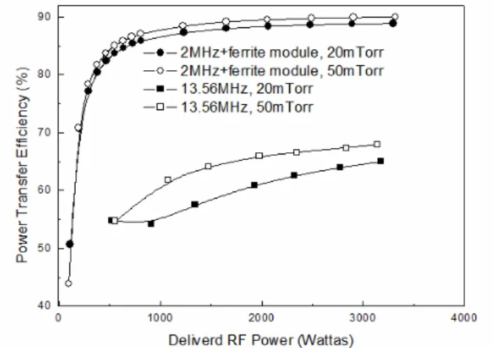
Fig. 3. Power transfer efficiency with the ICP source operated at 13.56MHz and 2MHz (with the ferrite module) measured by an impedance analyzer as functions of RF power.
Fig.3 shows the power transfer efficiency calculated for the floated antenna. The power transfer efficiency was calculated from the relationship among the input power to the antenna, the RF RMS current, and the resistance.
100 /
)
(Inputpower−Irf2R Inputpower× .[7]
Here,
I
rf2R
(PJoule Loss = I2RF ⅹR) is the Joule loss consumed through the current flowing on the antenna. As shown in the figure, with the increase of RF power, the power transfer efficiency with the ICP source operated at 2MHz with ferrite module is increased with the increase of RF power and, at 3.5kW of RF power, the power transfer efficiency of about 88% is obtained.The plasma uniformity was measured along the antenna line of the ICP source operated at 13.56MHz and 2MHz (with the ferrite module) with a home-made movable four-tip electrostatic probe system. For the operation of 13.56MHz, rf power in the range from 4000 to 8000W was used and, for 2MHz with
the ferrite module, the rf power from 1000 to 4000W was used. Ar 20mTorr was used for both cases. The probe system having the width of 240mm (80mm distance between the tips) was scanned along the antenna line of 2300mm. Ion saturation currents were measured at the tips biased at -60V. In the case of the ICP source operated at 13.56MHz, the ion saturation current was significantly varied along the antenna line of the ICP source at all of the rf powers (power input side showed higher plasma density than the other side). However, in the case of the ICP source operated at 2MHz with the ferrite module, the variation of ion saturation current was not significant along the antenna line at a given rf power and the change of rf power also did not change the uniformity significantly. When, the uniformity of ion saturation currents are compared at 4000W of rf power, the ICP source at 13.56MHz showed about 35% while that at 2MHz with the ferrite module showed about 11%. (not shown)
4. CONCLUSIONS
In this study, the use of line-type ICP source having a U-shaped internal linear ICP antenna with ferrite module showed high density plasmas higher than 4.0 × 10¹¹/cm3 by the operation at 2MHz and at the power of 3500W. However, the operation of the source at 13.56MHz showed highly non-uniform plasma uniformity along the antenna line (about 35% at 4000W rf power and 20mTorr Ar) in addition to high Joule loss and low power transfer efficiency. However, when the source was operated at 2MHz after the installation of a ferrite module for the magnetic field enhancement and confinement below the antenna line, the source showed higher plasma densities. In addition, better plasma uniformity along the antenna line (about 11% at 4000W and 20mTorr Ar) could be obtained in addition to lower Joule loss. The higher uniformity obtained at 2MHz compared to that at 13.56MHz is related to the lack of standing wave effect and higher plasma density is related to the magnetic confinement of the plasma by the ferrite module.
5. References
[1] Y. Sakawa, K. Yano, and T. Shoji, J. Vac. Sci. Technol. A 2004, 22, L7.
[2] H. Yamakoshi, K. Satake, Y. Takeuchi, H. Mashima, T. Aoi, Appl. Phys. Lett. 2006, 88, 081502.
[3] S. Xu, K. N. Ostrikov, Y. Li, E. L. Tsakadze, I. R. Jones, Physics of Plasmas. 2001, 8, 2549.
P2-78 / J.-H. Lim
IMID 2009 DIGEST • [4] Y. Wu, M. A. Liberman, Appl. Phys. Lett. 1998, 72,
777.
[5] N.Spiliopous, D.Mataras, and D.E.Rapakoulias, J. Vac. Sci. Technol. A. 1996, 14, 2757.
[6] ] J H Lim, K N Kim, G H Gweon, G Y Yeom, J. Phys. D: Appl. Phys, 2009,42, 15204.
[7] J. Hopwood, Plasma Source Sci. Technol. 1994, 3, 460.