An experimental study on the factors for the performance of a shutoff unit
in the half-core test loop of HANARO
Kyoung-Rean Kim and Yeong-Garp Cho
HANARO Center, Korea Atomic Energy Research Institute,
150 Deokjin-dong Yuseong-gu Daejeon, 305-353, R.O.KOREA Tel : 82-42-868-8174, E-mail : [email protected]
1. Introduction
The shutoff unit was designed to provide rapid insertion of neutron absorbing material into the reactor core to shut down the reactor quickly and also to withdraw the absorber slowly to avoid a log-rate trip. Four shutoff units were installed on the HANARO reactor but the half-core test facility was equipped with one shutoff unit. The hydraulic pump, pipe and air supply system are provided to be similar with the HANARO reactor. The shutoff rod drops for 647 mm stroke within 1.13 seconds to shut down the reactor and it is slowly inserted to the full down position, 700 mm, with a damping.
We have conducted the drop test of the shutoff rod in order to show the performance and the structural integrity of operating system of the shutoff unit. The present paper deals with the 647mm drop time and the withdrawal time according to variation of the pool water temperature, the water level and the core flow.
2. Experimental facility
2.1. Layout of the shutoff unit test systems
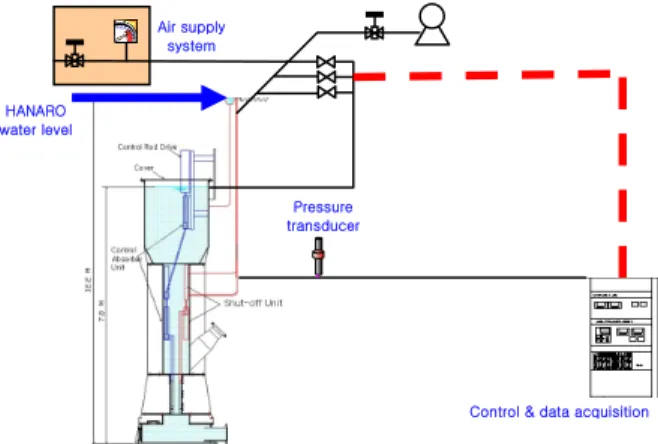
Fig. 1 shows the system schematic of the experimental facility for the operation of the shutoff unit. The test system of the shutoff unit consists of hydraulic cylinder, air supply system, solenoid valves, piston valves, hydraulic pump, pressure transducer and data acquisition system. When the shutoff rod drops, the hydraulic damping unit and compressible spring installed inside the cylinder absorber the high impact load. The pressure switches respectively provided in the upper part and the lower part of the cylinder can detect the arrival state of the shutoff rod. The piston installed inside the cylinder is freely moved up and down. The hydraulic pump has a duty that supplies water into the cylinder. The flow control valves equipped between that pump and the hydraulic cylinder can finely control the withdrawal velocity of the shutoff rod. Measurements were made by using a pressure transducer that acquires 1000 data per one second.
Fig. 1 System schematic of the experimental facility
2.2 Principle of the shutoff rod’s driving
The shutoff rod is maintained at the top of the core on the stand-by status using supplying continually the water inside the hydraulic cylinder. If the drop signal of the shutoff rod happens, the power of three solenoid valves is made off-condition. In result, the piston valves are opened because the air pressure supplied in the piston valves is automatically intercepted. Therefore, the water supplied into the hydraulic cylinder from the hydraulic pump is bypassed into the pool through the piston valves and then the shutoff rod drops by the gravity to shut down the reactor.
Fig. 2 Flow diagram of the shutoff unit hydraulic system
HANARO water level Air supply system Pressure transducer
Control & data acquisition Transactions of the Korean Nuclear Society Autumn Meeting
3. Experimental results and discussion
3.1. Drop and Withdrawal times
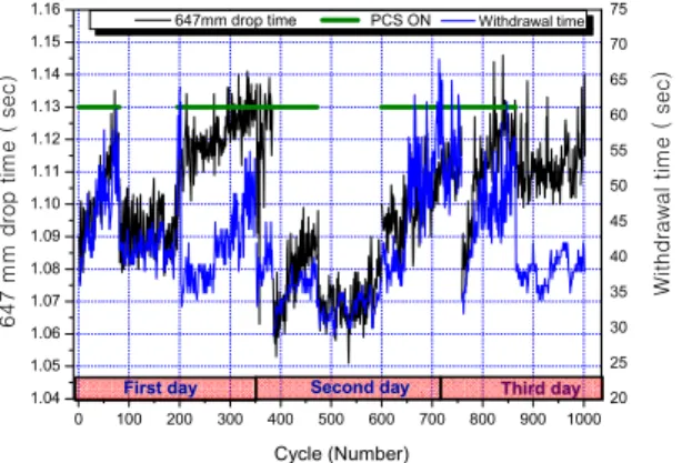
The experimental results of the drop time and withdrawal time are shown on Fig. 3. The 647mm drop times of the shutoff rod were in the range of 1.05 to 1.125 sec which meet the design requirement, 1.13 seconds. The 647mm drop time of the shutoff rod during PCS(primary coolant system) pump operation is longer than that when the PCS pump was turned off as shown in Fig. 3 because of the hydraulic drag force generated by the primary coolant flow.
The withdrawal time was also longer in case of PCS pump ON. The turbulent core flow might cause flow-induced-vibration of the shutoff rod which obstructs the withdrawal of the shutoff rod.
Fig. 3 647mm drop time and withdrawal time according to PCS variation
3.2 647mm drop time with water level
Fig. 4 shows that 647mm drop time of the shutoff rod decreases with increasing water level.
0 10 20 30 40 50 60 70 80 90 1.04 1.06 1.08 1.10 1.12 12.15 12.20 12.25 12.30 12.35 Cycle (Number) Wa te r le ve l (m) 64 7 mm d rop ti m e ( s e c )
647mm drop time Water level
Fig. 4 647mm drop time with the water level
3.3. Withdrawal time with pool water temperature Fig. 5 shows the withdrawal time of the shutoff rod according to temperature variation. The withdrawal test is conducted when the pool water temperature is between 33℃ and 37℃. The withdrawal time becomes longer when the temperature of the pool water is increased.
0 10 20 30 40 50 60 70 80 25 30 35 40 45 50 55 60 32 33 34 35 36 37 Cycle (Number) Te mp e ra ture (℃ ) Withdr aw al ti m e ( s ec) Withdrawaltime Temperature
Fig. 5 Withdrawal time with temperature variation
4. Conclusion
In the results of the drop time and withdrawal time of the shutoff rod, it was found that drop time and withdrawal time are affected by a variation of the pool water temperature, the water level and core flow. The higher the water level and the lower the pool water temperature are, the drop time and withdrawal time are faster. The measured data is considerably satisfied with design condition because drop time is within 1.13sec. The withdrawal time was adjustable between 28 and 60 seconds by two flow control valves with some margins.
REFERENCES
[1] AECL, “Test procedure KMRR shutoff unit”, SPEL 3700-33170-0001, TP-37-31730-003, 1992
[2] AECL, “Design manual shut off units”, DM-37-31730, 1993 [3] KAERI, “Safety analysis report”, KAERI/TR-710/96
0 100 200 300 400 500 600 700 800 900 1000 1.04 1.05 1.06 1.07 1.08 1.09 1.10 1.11 1.12 1.13 1.14 1.15 1.16 20 25 30 35 40 45 50 55 60 65 70 75 647 mm dr o p t ime ( s e c ) Cycle (Number) W it h dr awal tim e ( se c)
647mm drop time PCS ON Withdrawal time
F