Holographic inscription of helical wavefronts in a liquid crystal polarization grating
Hyunhee Choi, J. H. Woo, and J. W. WuDong-Wook Kim and Tong-Kun LimSeok Ho Song
Citation: Appl. Phys. Lett. 91, 141112 (2007); doi: 10.1063/1.2793173 View online: http://dx.doi.org/10.1063/1.2793173
View Table of Contents: http://aip.scitation.org/toc/apl/91/14 Published by the American Institute of Physics
Holographic inscription of helical wavefronts in a liquid crystal polarization
grating
Hyunhee Choi, J. H. Woo, and J. W. Wua兲
Department of Physics and Division of Nano Sciences,Ewha Womans University, Seoul 120-750, Korea
Dong-Wook Kim and Tong-Kun Lim
Department of Physics, Korea University, Seoul 136-713, Korea
Seok Ho Song
Department of Physics, Hanyang University, Seoul 133-791, Korea
共Received 27 June 2007; accepted 11 September 2007; published online 3 October 2007兲
A space-varying polarization hologram 共PH兲 grating is fabricated in a nematic liquid crystal 共LC兲 cell with azo-side-chain polymer alignment layers. The polarization-sensitive photoisomerization property of azo-side-chain polymer is utilized to inscribe the PH in a LC cell. Both transmission and reflection holographic configurations are adopted in fabrication. The transmission PH made by the circular orthogonal polarizations exhibits the polarization-controlled Laguerre-Gaussian beam generation, while the reflection PH made by the linear orthogonal polarizations generates a variety of Laguerre-Gaussian beam, though not polarization controlled. © 2007 American Institute of
Physics. 关DOI:10.1063/1.2793173兴
Photon possesses orbital angular momentum 共OAM兲 as well as spin angular momentum,1and it has been pointed out that the photon’s OAM is another degree of freedom in pre-paring a quantum state of light for quantum optics.2–4 To generate Laguerre-Gaussian 共LG兲 beams possessing OAM from a planar wavefront beam, various means have been employed including a mode converter by a set of cylindrical lens, a spiral phase plate, and a computer generated holo-gram共CGH兲. In all the above examples, however, the polar-ization state of the LG helical wavefront remains the same as that of the incident beam.
If control of the OAM state by the input polarization is facilitated in the LG beam generator, a versatility is provided in preparing the OAM state, enabling a wide open design capability for photonic circuit incorporating multistate infor-mation encoding in quantum communication.5For example, it is possible to switch among different OAM’s by a fast electro-optic control of the input polarization. Related to this, a nematic planar liquid crystal 共LC兲 q-plate structure has been demonstrated as a polarization controlled LG beam generator, providing LG02 helical modes.6–8
On the other hand, polarization grating is an optical el-ement where the incident beam undergoes a polarization change upon diffraction. In the holographic fabrication of a polarization grating, two orthogonally polarized beams inter-fere inside a polarization-sensitive recording medium, im-printing a replica of the polarization interference pattern as a polarization hologram共PH兲.9,10 If a helical wavefront beam is made to interfere with a planar wavefront reference in an orthogonal polarization configuration, the resulting PH grat-ing possesses a space-varygrat-ing polarization modulation and works as a polarization controlled LG beam generator.
In this letter, we report on the fabrication of a space-varying polarization hologram共SVPH兲 grating in a nematic LC cell with azo-side-chain polymer alignment layers. The polarization-sensitive photoisomerization property of
azo-side-chain polymer is utilized to inscribe the PH in a LC cell. The polarization modulation gives rise to a PH in the LC cell through the photoisomerization of azo moieties on the pho-toalignment layer surface. Both transmission and reflection holographic configurations are adopted in fabrication. The diffraction order from the PH grating is characterized to find whether the LG beam generation can be controlled by the input polarization. The transmission PH made by the circular orthogonal polarizations exhibits the polarization-controlled LG beam generation, while the reflection PH made by the linear orthogonal polarizations generates a variety of LG beam, though not polarization controlled.
In order to inscribe the PH grating inside a birefringent nematic LC cell, we fabricated a nematic LC cell with azo-side-chain polymer alignment layers, following the proce-dure detailed in Ref.11. Two beams in orthogonal polariza-tions from the 514.5 nm line of an Ar+laser are adopted as writing beams. The intensity of writing beams is 200 mW/ cm2and the exposure time is 30 s. CGHs are used
to obtain helical wavefronts to inscribe a SVPH, which was stable at room temperature and ambient light environment.
First, we adopted a transmission holographic configura-tion with two beams in left-/right-circular orthogonal polar-izations. The 0 order and +1 order from the LG02 CGH co-propagate with a small intersecting angle, providing the interference of planar wavefront共LG00兲 and helical wavefront 共LG02兲 with the electric field of the linear polarization going
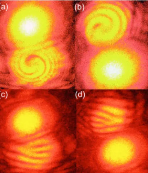
through a circular rotation.9,10Once the SVPH grating is fab-ricated, we set up a Mach-Zehnder interferometer共MZI兲 us-ing the light source of 632.8 nm He–Ne laser, in order to identify the detailed phase front shape of the diffracted or-ders. Figures1共a兲and1共c兲关Figs.1共b兲and1共d兲兴 show the +1 共−1兲 diffraction order for a right- 共left-兲circularly polarized planar wavefront. We find that there appears only positive or negative mode helical wavefront diffraction order with the sense of circular polarization reversed. That is, the helical mode of diffraction order LG beam depends on the polariza-tion state of reference planar wavefront. Space-varying
po-a兲Electronic mail: [email protected]
APPLIED PHYSICS LETTERS 91, 141112共2007兲
larization state manipulation has been demonstrated in a midinfrared wavelength by use of the subwavelength grating technology because of the difficulty in mechanical fabrica-tion of a polarizafabrica-tion grating with the period comparable to the optical wavelength.12Our SVPH grating, fabricated by a transmission holographic configuration, allows the desired space-varying polarization state manipulation in the range of the visible wavelength. Although it is straightforward to fab-ricate LG beam generator with helical modes other than LG02, our example shows that the q-plate structure can be readily attained by a SVPH grating fabrication.
Next, in order to further investigate the versatility of the PH in generating helical wavefronts, we extended our study to a reflection holographic configuration. Refer to the reflec-tion holographic configurareflec-tion shown in Fig.2. We inscribed three PHs by superimposing different diffraction orders gen-erated from the LG01 CGH, that is, the 0 and ±1 orders. The three PHs are共a兲 the interference of two +1 orders of helical wavefronts 共LG01兲, 共b兲 the interference of 0 order planar wavefront共LG00兲 and +1 order of helical wavefront 共LG01兲, and 共c兲 the interferencem of +1 and −1 orders of helical wavefronts 共LG01 and LG0−1兲. In each case, the resulting
space-varying phase difference 共x,y兲 is 共a兲 zero, 共b兲 tan−1共y/x兲, and 共c兲 2 tan−1共y/x兲. Once the PH is inscribed into the LC cell, the LC polarization domains inside the PH grating were examined by a polarized microscopy. Figures 3共a兲–3共c兲are the textures of LC domains of three PHs ob-served in the polarized microscopy, corresponding to the PHs 共a兲–共c兲. In the PH 共a兲, the phase difference is independent of
y, resulting in a linear polarization grating with the grating
vector along x axis, as seen in Fig.3共a兲. Note that there exists a central blurred spot where no polarization grating pattern is present, which results from the fact that both writing helical wavefronts have zero light intensity at the center of beams profile due to the phase singularity of a helical mode, and no photoisomerization process takes place in the region of the zero light intensity of two superimposed beams, hence no rotations of LC molecules. In Fig.3共b兲, corresponding to the PH 共b兲, LC polarization domains have a pattern of a two-pronged fork grating in the polarized microscopy texture. Figure 3共c兲, corresponding to the PH 共c兲, shows three-pronged fork grating patterned LC polarization domains. Here, similar to the patterns in Fig.3共a兲a central disk of zero light intensity formed by two superimposed helical modes leaves the LC molecules within the disk unrotated, which results in the breaking of the central prong at the branching point of the three-pronged fork.
The observed LC polarization domain structure of the space-varying polarization LC grating can be understood from a theoretical simulation of the polarization modulation on the hologram surface. Figure4共a兲is the simulation result of the interference modulation formed by a helical wavefront LG01and a planar wavefront LG00beams. The left part of Fig. 4共a兲 is colored for ease of illustration of the polarization grating shape. The red and blue domains are adjacent to each other, the LC directors of two domains are oriented in oppo-site angles with respect to the y axis, and the spatial distri-bution of two domains has one dislocation on the y axis, which is the fork grating. Figure4共b兲is the enlarged figure of the rectangular area of Fig. 4共a兲, showing the detailed
peri-FIG. 1.共Color online兲 共a兲 and 共c兲 关共b兲 and 共d兲兴 show the +1 共−1兲 diffraction order for the right-共left-兲circularly polarized planar wavefront.
FIG. 2. 共Color online兲 The slanted reflection holographic configuration to inscribe the S- and P-polarization modulations.共a兲–共c兲 in the PH LC grating correspond to the recording condition for Figs. 3共a兲–3共c兲, respectively. 共CGH: computer generated hologram of LG01mode, BS: beam splitter, HW:
half-wave plate, and M: Mirror.兲
FIG. 3.共Color online兲 The microscopic texture of PHs 共a兲 LG01and LG 0 1,共b兲 LG01and LG 0 0, and共c兲 LG 0 1and LG 0
−1mode writing beams,
counterpropagat-ing in linear orthogonal S / P polarizations.
FIG. 4.共Color online兲 Simulation of PH grating, shown in Fig.3共b兲.共b兲 The enlarged image of rectangular part of共a兲 with the polarization modulations of a reverse twisted LC domain.
odic polarization modulation change due to the phase differ-ences. Differently from the transmission hologram, the re-flection hologram gives rise to the LC polarization grating in the structure of reverse twisted nematics共RTNs兲, which we call the space-varying RTN polarization grating.11
In order to understand how the polarization state will change upon diffraction from the space-varying RTN polar-ization grating, the Jones matrix should be derived, which can be done by taking into account the spatial distribution of two TN domains with opposite sense of rotation. Aside from the optical phase term coming from the space-varying phase difference, the resultant Jones matrix takes the following form:
M0=
冉
a + b 00 a − b
冊
,M±1= ±
冉
0 c − dc + d 0
冊
, 共1兲where a – d are complex numbers determined by the geomet-ric dimensions of the grating such as birefringence ne-no, cell
thickness, the tilt angle, and the off-set angle of TN inside the grating. We note that Jones matrix forms of the 0 and ±1 orders are different. When the incident beam is S-or
P-linearly polarized, the ±1 diffraction orders get the
polar-ization changed, while the 0 order keeps the polarpolar-ization unchanged. For a left-or right-circular polarized beam, both 0 and ±1 diffraction orders are in an elliptical polarization, the ellipticity being determined by the ratios a / b and d / c.
Now, we investigate the diffraction characteristics of the space-varying RTN polarization grating by irradiating with the S-linearly polarized probe beam of 632.8 nm He–Ne la-ser. As shown in Fig. 5共a兲, the ±1 diffraction orders have annular intensity distributions and the polarization was mea-sured to be 90° rotated, while the 0 diffraction order has a Gaussian intensity distribution with the polarization state un-changed. In order to identify the detailed phase front shape
of diffracted orders from the RTN polarization grating, we set up a MZI again. There occurs an intensity modulation with the intensity fringe patterns, as shown in Figs.5共b兲–5共d兲 each corresponding to the PH in Figs.3共a兲–3共c兲, respectively. We clearly observe a linear, a two-pronged fork, and a three-prong fork shaped fringe patterns.
When a right- 共left-兲circularly polarized planar wave-front beam is incident on the grating, the intensity fringe patterns were observed to be the same as those in Fig. 3, while the polarizations of both 0 and ±1 diffraction orders are measured to be linearly polarized with the polarization direction making an angle of −45°共+45°兲 relative to the y axis. We estimated the experimental values of the tilt angle and the off-set angle and obtained the ratio of⬇1 for both
a / b and d / c, which corresponds to a linear polarization
ac-cording to Eq.共1兲.
In summary, we fabricated a space-varying polarization hologram grating in a LC cell. Depending on the configura-tion of two orthogonal polarizaconfigura-tions of writing beams, a va-riety of polarization control of LG beam generation can be achieved. In the transmission hologram, the helical mode of the diffraction order can be controlled by the input polariza-tion of a planar wavefront. In the transmission hologram, the reverse twisted nematic polarization grating was fabricated, which generates LG helical wavefront possessing an orbital angular momentum.
J.W.W. acknowledges the support by Seoul Research and Business Development Program共10816兲, by ABRL program, and by Korea Research Foundations 共KRF-2006-005-J04001兲, and S.H.S. acknowledges the support by OPERA ERC program.
1L. Allen, S. M. Barnett, and M. J. Padgett, Optical Angular Momentum
共Institute of Physics, Bristol, 2003兲.
2A. Mair, A. Vaziri, G. Weihs, and A. Zeilinger, Nature共London兲 412, 313
共2001兲.
3J. Leach, M. J. Padgett, S. M. Barnett, S. Franke-Arnold, and J. Courtial,
Phys. Rev. Lett. 88, 257901共2002兲.
4A. Vaziri, G. Weihs, and A. Zeilinger, Phys. Rev. Lett. 89, 240401共2002兲. 5G. Gibson, J. Courtial, M. J. Padgett, M. Vasnetsov, V. Pas’ko, S. Barnett,
and S. Franke-Arnold, Opt. Express 12, 5448共2004兲.
6L. Marrucci, C. Manzo, and D. Paparo, Appl. Phys. Lett. 88, 221102
共2006兲.
7L. Marrucci, C. Manzo, and D. Paparo, Phys. Rev. Lett. 96, 163905
共2006兲.
8D. Voloschenko and O. D. Lavrentovich, Opt. Lett. 25, 317共2000兲. 9H. Ono, A. Emoto, F. Takahashi, N. Kawatsukib, and T. Hasegawa, J.
Appl. Phys. 94, 1298共2003兲.
10L. Nikolova and T. Todorov, Opt. Acta 31, 579共1984兲.
11H. Choi, H. J. Chang, B. Park, and J. W. Wu, Appl. Phys. Lett. 88, 021905
共2006兲.
12Z. Bomzon, G. Biener, V. Kleiner, and E. Hasman, Opt. Lett. 27, 1141
共2002兲. FIG. 5.共Color online兲 Diffraction orders from PH shown in Fig.3共b兲.共b兲–
共d兲 are the interference patterns of +1 order from PH in Figs.3共a兲–3共c兲with a planar wavefront reference, respectively.