Introduction
Dental implant treatments have provided an
alter-native to conventional fixed dental prosthesis that requires preparation of the adjacent teeth1). The
im-plant surgery was essentially based on two-dimen-J Korean Dent Sci. 2020;13(1):28-34 https://doi.org/10.5856/JKDS.2020.13.1.28 pISSN 2005-4742 ∙∙ eISSN 2713-7651
Corresponding Author: Du-Hyeong Lee, https://orcid.org/0000-0003-2803-7457
Department of Prosthodontics, School of Dentistry, Institute for Translational Research in Dentistry, Kyungpook National Uni-versity, 2175 Dalgubeol-daero, Jung-gu, Daegu 41940, Korea
TEL : +82-53-600-7651, FAX : +82-53-427-0778, E-mail : [email protected]
Received for publication May 12, 2020; Returned after revision June 12, 2020; Accepted for publication June 15, 2020
Copyright © 2020 by Korean Academy of Dental Science
cc This is an open access article distributed under the terms of the Creative Commons Attribution Non-Commercial License (http://creativecommons.org/licenses/ by-nc/4.0) which permits unrestricted non-commercial use, distribution, and reproduction in any medium, provided the original work is properly cited.
Accuracy of the Point-Based Image Registration
Method in Integrating Radiographic and
Optical Scan Images: A Pilot Study
Hai Yen Mai
1, Du-Hyeong Lee
1,21Department of Prosthodontics, School of Dentistry, Kyungpook National University, 2Institute for Translational Research in Dentistry, Kyungpook National University, Daegu, Korea
Purpose: The purpose of this study was to investigate the influence of different implant computer software on the
accuracy of image registration between radiographic and optical scan data.
Materials and Methods: Cone-beam computed tomography and optical scan data of a partially edentulous jaw
were collected and transferred to three different computer softwares: Blue Sky Plan (Blue Sky Bio), Implant Studio (3M Shape), and Geomagic DesignX (3D systems). In each software, the two image sets were aligned using a point-based automatic image registration algorithm. Image matching error was evaluated by measuring the linear discrepancies between the two images at the anterior and posterior area in the direction of the x-, y-, and z-axes. Kruskal–Wallis test and a post hoc Mann–Whitney U-test with Bonferroni correction were used for statistical analyses. The signifi-cance level was set at 0.05.
Result: Overall discrepancy values ranged from 0.08 to 0.30 µm. The image registration accuracy among the
soft-ware was significantly different in the x- and z-axes (P=0.009 and <0.001, respectively), but not different in the y-axis (P=0.064).
Conclusion: The image registration accuracy performed by a point-based automatic image matching could be
differ-ent depending on the computer software used.
sional periapical or panoramic radiographs2,3). With
the introduction of the cone-beam computed tomog-raphy (CBCT) to the dental field, three-dimensional (3D) images of critical anatomical structures such as the inferior alveolar nerve, maxillary sinus, and roots of neighboring teeth were started and evaluated ac-curately in the diagnostic modalities and treatment planning4,5).
Implant guide templates are the physical tools that transfer the implant position planning to the surgical site inside the oral cavity6). With the widespread use
of CBCT, the development of dental computer-aided design and computer-assisted manufacturing (CAD/ CAM) helped to realize the restoratively driven im-plant placement concept7). The CAD/CAM
technol-ogies enhanced the accuracy of implant placement and the convenience of the fabrication of surgical guides by reducing the manual work8). Accordingly,
these 3D imaging and computerized works have contributed to optimize implant treatments to be more evidence based, safer, and quicker from both a prosthodontic and a surgical point of view9).
Implant guide systems can be classified as bone, tooth, or mucosa-supported types according to the structure on which the guides are supported10). A
sys-tematic review compared the accuracy of different implant guide support types and showed that the accuracy of the implant placement is not consistent among studies11). The total error of implant
place-ment depends on the summation of the possible er-rors that are involved in all the clinical treatment and fabrication steps of the implant protocol11). The error
sources could be the 3D radiographic image taking, intraoral optical scanning, image registration pro-cess, guide sleeve design, 3D printing propro-cess, guide positioning, and unskilled guided surgery perfor-mance11,12).
Image registration in the computer-assisted guide fabrication is the process of aligning the optical scan image of the oral cavity surface to the correspond-ing CBCT data13). However, because the gingival
structure cannot be shown in the CBCT images, the merging of the 3D optical scan image of the oral cav-ity to the CBCT images is a prerequisite for accurate diagnosis and guide designing, especially for tissue-supported guide templates14). For the alignment of
the two data sets, implant planning software are used. First, anatomical landmarks shown in both CBCT and optical scan images are selected by opera-tors and then, further alignment is processed using the automatic best-fit algorithm15).
The image registration is an important process that replicates the relation of soft tissue and hard tissue. When the alignment of optical scan images to CBCT is not accurate, critical errors in implant position can occur16). The purpose of this study was to assess the
effects of implant planning software on the accuracy of image registration of optical scan to CBCT data. The proposed null hypothesis was that the difference in implant software would not result in different im-age matching accuracy between the optical scan and CBCT data for computer-guided implant surgery.
Materials and Methods
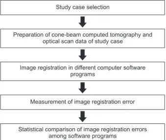
The workflow of this study is described in Fig. 1. Within the patients who required implant surgery, a patient was selected as per the following inclusion criteria: partial edentulous dental arch, no metallic restoration, no large tooth structure defect. Patients who had edentulous dental arch and were not planned to undergo guided surgery were excluded. Based on the criteria, a partially edentulous maxilla case with missing of teeth 15 and 16 was selected for this study. Implant-supported fixed dental pros-thesis was planned in the edentulous area to restore the chewing function and esthetics. To prepare the computer-guided implant placement, radiographic data of computer tomography were obtained using a CBCT device (Pax-i3D Smart; Vatech, Hwaseong, Korea) with 89 kVp, 8 mA, 24 seconds pulsed scan, field of view of 120×85 mm, and slice thickness of
0.3 mm. The radiographic data was saved in digital imaging and communications in medicine (DICOM) format. An optical scan image of the surface of the oral cavity was obtained by scanning the stone cast that had been made by silicone impression using a lab-based scanner (IDC S1; Amann Girrbach, Ko-blach, Austria). The scan image was saved in the for-mat of standard tessellation language (STL).
The image registration of optical scan to radio-graphic data was performed in three different computer software: Blue Sky Plan (BSP) (Blue Sky Bio LLC, Grayslake, IL, USA), Implant Studio (IS) (3Shape, Copenhagen, Denmark), and Geomagic DesignX (GD) (3D Systems, Rock Hill, SC, USA). The DICOM and STL files were transferred to each software, where the two 3D images were matched
by a point-based automatic alignment method (Fig. 2). As fiducial points for the image matching, the incisal line angle of tooth 11 and mesio-buccal cusp tip of tooth 17 and 27 were used. After the point des-ignation, the automatic image matching with best-fit algorithm was followed.
After the image registration, the accuracy of the image matching was assessed by measuring linear discrepancies between the images at the anterior and posterior areas (tooth 11 and 17) in the direction of the x-, y-, and z-axes (Fig. 3). The measurements were conducted in the cross-sectional view of teeth at the frontal, sagittal and transverse planes using the measurement function of each implant plan-ning software (Fig. 4). All the image registration and
Study case selection
Preparation of cone-beam computed tomography and optical scan data of study case
Image registration in different computer software programs
Measurement of image registration error
Statistical comparison of image registration errors among software programs
Fig. 1. Workflow of this study.
Fig. 2. Image registration pro cess between radiographic and optical scan data using point based automatic image match ing.
Fig. 3. Threedimensional coordinates for matching discrepancy measurement.
measurement processes were carried out 5 times at 1-week intervals by a single investigator who was blinded to the purpose of this study to avoid inter-examiner related bias.
The mean accuracy of image registration in each software program was calculated by averaging the discrepancy values collected in the anterior and posterior areas, and compared between the different software. Kruskal–Wallis test and a post hoc Mann– Whitney U-test with Bonferroni correction were used for statistical analyses. The significance level was set at 0.05.
Result
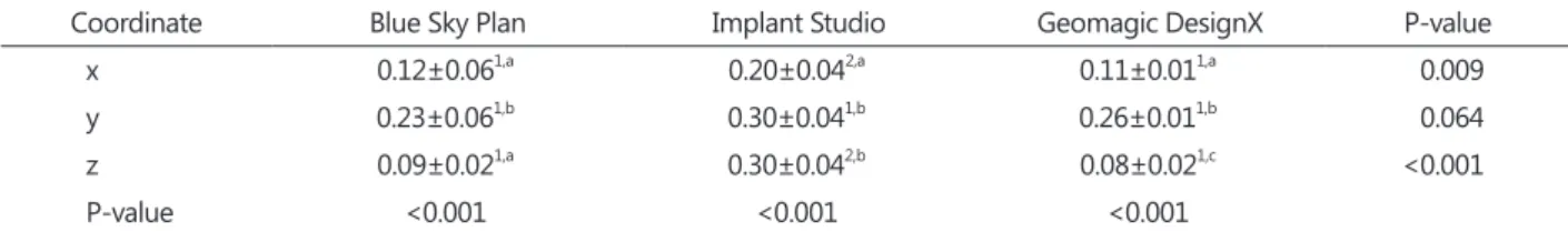
The linear discrepancies of image registration in each software program are presented in Table 1. The
IS software showed significantly higher discrepancy values than the BSP and GD software in the x- and z-axes (P=0.009 and <0.001, respectively). In the y-axis, no difference was found between the software (P=0.064). With regards to the measurement axis, even though the discrepancy values were different between the axes in all the software (P<0.001), there was no trend in the results. Generally, discrepancy values ranged from 0.08 to 0.30 µm (Fig. 5).
Discussion
This study was designed to investigate the accura-cy of image registration of optical scan to CBCT data in different implant planning software. The results showed that all image registration errors were lower than 0.30 µm in every axis and that the accuracy of image matching was statistically different between the tested software. These findings imply that the
0.08 mm
0.22 mm
Fig. 4. Representative view for linear discrepancy measurement.
Blue Sky Plan
4.0 3.6 3.2 2.8 2.4 2.0 1.6 1.2 0.8 0.4 Image registration discrepancy (mm)
Implant software program 0.0
Implant Studio Geomagic DesignX
X axis Y axis Z axis
Fig. 5. Linear discrepancy of image registration in different com puter software.
Table 1. Linear discrepancy of image registration between radiographic and optical scan images in different computer software
Coordinate Blue Sky Plan Implant Studio Geomagic DesignX Pvalue
x 0.12±0.061,a 0.20±0.042,a 0.11±0.011,a 0.009
y 0.23±0.061,b 0.30±0.041,b 0.26±0.011,b 0.064
z 0.09±0.021,a 0.30±0.042,b 0.08±0.021,c <0.001
Pvalue <0.001 <0.001 <0.001
Values are presented as mean±standard deviation.
a,bSignificant differences within a row are represented by the different alphabetical letters. 1,2Significant differences within a column are represented by the different numbers.
computer programs had different image matching performances, even though they used the same im-age alignment method. Thus, the null hypothesis stating that the difference in implant software would not result in different image matching accuracy be-tween the optical scan and CBCT data was rejected.
Surface-based image registration is the basic method described for 3D image superimposition17,18).
In the contemporary point-based automatic image matching techniques, the registration of 3D scanner models to CBCT data requires manual selection of the matching points19,20). Accordingly, the principle
involves approximating two surfaces by selecting corresponding landmarks on the two images. Setting the appropriate reference points is the first step in obtaining reliable data for comparing the accuracy. The clinicians choose arbitrarily at least three pair of points in common between the radiographic and scan data. An increase in the number of registra-tion points had no significant effect on the accuracy of the prosthetic treatment plan incorporation21,22).
This image registration protocol is applicable when enough number of points could be used and were largely distributed in the oral cavity, because this condition is important to have favorable matching situations13,23). To reliably serve for registration, the
reference areas should be clearly discernible in the respective images to be registered24). The use of
point-based image matching workflow for guided implant surgery is known to be advantageous because this method is clinically feasible and time-efficient.
After the manual designation of the matching points, automatic image alignment is processed. Namely, based on the reference points, best-fit image registration is performed by means of software func-tions15). In this study, the three software used
itera-tive closest point (ICP) algorithm that minimized the surface distance between the two surfaces. The ICP algorithm is graphic processing and can facilitate the alignment of the 3D polygon mesh data sets of the digital models25). Although the established
reg-istration framework ICP is currently used for dental applications, the present study identified that the quality of ICP could be different depending on the software used.
Several clinical concerns should be included in further studies. When a patient has prostheses made of metal alloys, image artifacts can occur due to the cone-beam hardening effect, which causes distor-tion and deformadistor-tion of the images26). The difference
in shape between the 3D radiographic image with artifacts and optical scan image can cause inaccurate automatic alignment results. Image registration is also affected by the number of missing teeth and length of edentulous ridges. Moreover, human error in selecting the matching is considered because the point designation depends on the decision making and proficiency of the operators.
Conclusion
Within the limitation of this in vitro study, accuracy of image registration performed by point-based au-tomatic image matching could be different depend-ing on the computer software used for guided im-plant surgery. Further studies are needed to confirm the findings of this study in various clinical setting and using other software.
Conflict of Interest
No potential conflict of interest relevant to this ar-ticle was reported.
References
1. Pjetursson BE, Brägger U, Lang NP, Zwahlen M. Comparison of survival and complication rates of tooth-supported fixed dental prostheses (FDPs) and implant-supported FDPs and single crowns (SCs). Clin Oral Implants Res. 2007; 18(Suppl 3): 97-113. 2. Noharet R, Pettersson A, Bourgeois D. Accuracy of
implant placement in the posterior maxilla as relat-ed to 2 types of surgical guides: a pilot study in the human cadaver. J Prosthet Dent. 2014; 112: 526-32. 3. Scherer U, Stoetzer M, Ruecker M, Gellrich NC, von
See C. Template-guided vs. non-guided drilling in site preparation of dental implants. Clin Oral Inves-tig. 2015; 19: 1339-46.
4. Marchack CB. CAD/CAM-guided implant surgery and fabrication of an immediately loaded prosthesis for a partially edentulous patient. J Prosthet Dent. 2007; 97: 389-94.
5. Park C, Raigrodski AJ, Rosen J, Spiekerman C, Lon-don RM. Accuracy of implant placement using pre-cision surgical guides with varying occlusogingival heights: an in vitro study. J Prosthet Dent. 2009; 101: 372-81.
6. Garber DA, Belser UC. Restoration-driven implant placement with restoration-generated site develop-ment. Compend Contin Educ Dent. 1995; 16: 796, 8-802, 4.
7. D'Souza KM, Aras MA. Types of implant surgical guides in dentistry: a review. J Oral Implantol. 2012; 38: 643-52.
8. Koop R, Vercruyssen M, Vermeulen K, Quirynen M. Tolerance within the sleeve inserts of different sur-gical guides for guided implant surgery. Clin Oral Implants Res. 2013; 24: 630-4.
9. Holst S, Blatz MB, Eitner S. Precision for computer-guided implant placement: using 3D planning software and fixed intraoral reference points. J Oral Maxillofac Surg. 2007; 65: 393-9.
10. Ozan O, Turkyilmaz I, Ersoy AE, McGlumphy EA, Rosenstiel SF. Clinical accuracy of 3 different types of computed tomography-derived stereolitho-graphic surgical guides in implant placement. J Oral Maxillofac Surg. 2009; 67: 394-401.
11. Raico Gallardo YN, da Silva-Olivio IRT, Mukai E, Morimoto S, Sesma N, Cordaro L. Accuracy com-parison of guided surgery for dental implants ac-cording to the tissue of support: a systematic review and meta-analysis. Clin Oral Implants Res. 2017; 28:
602-12.
12. Lee DH, An SY, Hong MH, Jeon KB, Lee KB. Accu-racy of a direct drill-guiding system with minimal tolerance of surgical instruments used for implant surgery: a prospective clinical study. J Adv Prostho-dont. 2016; 8: 207-13.
13. Flügge T, Derksen W, Te Poel J, Hassan B, Nelson K, Wismeijer D. Registration of cone beam computed tomography data and intraoral surface scans- a prerequisite for guided implant surgery with CAD/ CAM drilling guides. Clin Oral Implants Res. 2017; 28: 1113-8.
14. Mai HN, Kim KR, Lee DH. Non-radiological meth-od for fabrication of a screw-channel drilling guide in cement-retained implant restorations using intra-oral digital scanning and imaging superimposition: a clinical report. J Prosthodont. 2017; 26: 88-92. 15. Almukhtar A, Ju X, Khambay B, McDonald J,
Ayoub A. Comparison of the accuracy of voxel based registration and surface based registration for 3D assessment of surgical change following orthog-nathic surgery. PLoS One. 2014; 9: e93402.
16. Di Giacomo GA, Cury PR, de Araujo NS, Sendyk WR, Sendyk CL. Clinical application of stereolitho-graphic surgical guides for implant placement: pre-liminary results. J Periodontol. 2005; 76: 503-7. 17. Baik HS, Kim SY. Facial soft-tissue changes in
skel-etal Class III orthognathic surgery patients analyzed with 3-dimensional laser scanning. Am J Orthod Dentofacial Orthop. 2010; 138: 167-78.
18. Hajeer MY, Ayoub AF, Millett DT. Three-dimension-al assessment of faciThree-dimension-al soft-tissue asymmetry before and after orthognathic surgery. Br J Oral Maxillofac Surg. 2004; 42: 396-404.
19. Kim BC, Lee CE, Park W, Kang SH, Zhengguo P, Yi CK, Lee SH. Integration accuracy of digital dental models and 3-dimensional computerized tomogra-phy images by sequential point- and surface-based markerless registration. Oral Surg Oral Med Oral Pathol Oral Radiol Endod. 2010; 110: 370-8.
C, Lamoral P, Neyt N, Casselman J, Schutyser F. A cone-beam CT based technique to augment the 3D virtual skull model with a detailed dental surface. Int J Oral Maxillofac Surg. 2009; 38: 48-57.
21. Choi YS, Kim MK, Lee JW, Kang SH. Impact of the number of registration points for replacement of three-dimensional computed tomography images in dental areas using three-dimensional light-scanned images of dental models. Oral Radiol. 2014; 30: 32-7. 22. Jamjoom FZ, Yilmaz B, Johnston WM. Impact of
number of registration points on the positional ac-curacy of a prosthetic treatment plan incorporated into a cone beam computed tomography scan by surface scan registration: an in vitro study. Clin Oral Implants Res. 2019; 30: 826-32.
23. DE Vico G, Spinelli D, Bonino M, Schiavetti R, Pozzi A, Ottria L. Computer-assisted virtual treatment planning combined with flapless surgery and im-mediate loading in the rehabilitation of partial eden-tulies. Oral Implantol (Rome). 2012; 5: 3-10.
24. Sonka M, Fitzpatrick JM. Handbook of medical im-aging. Bellingham: SPIE Press; 2000. p. 447-506. 25. Chen J, Li S, Fang S. Quantification of tooth
dis-placement from cone-beam computed tomography images. Am J Orthod Dentofacial Orthop. 2009; 136: 393-400.
26. Schulze R, Heil U, Gross D, Bruellmann DD, Dra-nischnikow E, Schwanecke U, Schoemer E. Artefacts in CBCT: a review. Dentomaxillofac Radiol. 2011; 40: 265-73.