• 검색 결과가 없습니다.

Lubrication Analysis of Infinite Width Slider Bearing with a Micro-Groove: Part 2 - Effect of Groove Depth

N/A
N/A
Protected

Academic year: 2021

Share "Lubrication Analysis of Infinite Width Slider Bearing with a Micro-Groove: Part 2 - Effect of Groove Depth"

Copied!
7
0
0

로드 중.... (전체 텍스트 보기)

전체 글

(1)

DOI https://doi.org/10.9725/kts.2019.35.6.382

미세 그루브가 있는 무한폭 Slider 베어링의 윤활해석:

제2보 - 그루브 깊이의 영향

박태조1†ㆍ장인규2

1

경상대학교 기계공학부 · 공학연구원

2

경상대학교 기계항공정보융합공학부 학부생

Lubrication Analysis of Infinite Width Slider Bearing with a Micro-Groove: Part 2 - Effect of Groove Depth

TaeJo Park

1†

and InGyu Jang

2

1

School of Mechanical Engineering, ERI, Gyeongsang National University

2

Under-Graduate School, School of Mechanical & Aerospace Engineering, Gyeongsang National University (Received November 19, 2019 ; Revised December 5, 2019 ; Accepted December 6, 2019)

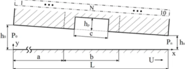
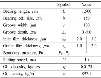
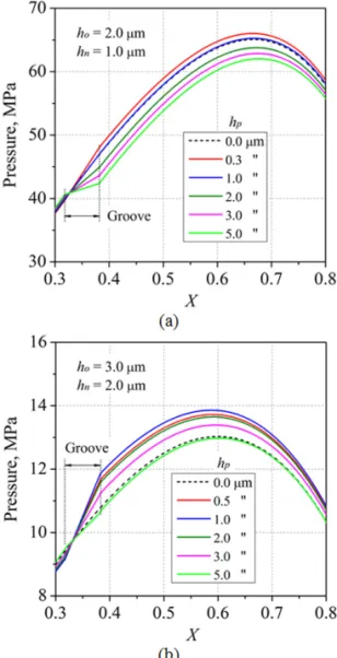
Abstract − It is currently well known that surface textures act as lubricant reservoirs, entrap wear debris, and hydrodynamic bearings, which can lead to certain increases in load-carrying capacities. Until recently, the vast majority of research has focused on parallel sliding machine components such as thrust bearings, mechanical face seals, piston rings, etc. However, most sliding bearings have a convergent film shape in the sliding direction and their hydrodynamic pressure is mainly generated by the wedge action. Following the first part of the present study that investigates the effect of groove position on the lubrication performances of inclined slider bearings, this paper focuses on the effects of groove depths and film thicknesses. Using a commercial computational fluid dynamics (CFD) code, FLUENT, the continuity and Navier–Stokes equations are numerically analyzed. The results show that the film thickness and groove depth have a significant influence on the pressure distribution.

The maximum pressure occurs at the groove depth where the vortex is found and, as the depth increases, the pres- sure decreases. There is also a groove depth to maximize the supporting load with the film thickness. The friction force acting on the slider decreases with deeper grooves. Therefore, properly designed groove depths, depending on the operating conditions, can improve the load-carrying capacity of inclined slider bearings as compared to the bearings without a groove.

Keywords – slider bearing( 슬라이더 베어링), surface texturing(표면조직가공), Navier–Stokes equation(나비 에-스톡스 방정식), hydrodynamic lubrication(유체윤활), numerical analysis(수치해석)

Nomenclature

Corresponding author: [email protected] Tel: +82-55-772-1623, Fax: +82-55-772-1577 https://orcid.org/0000-0002-5617-622X

ⓒ Korean Tribology Society 2019. This is an open access article distributed under the terms of the Creative Commons Attribution License(CC BY, https://creativecommons.org/

licenses/by/4.0/), which permits unrestricted use, distribution, and reproduction of the work in any medium, provided the original authors and source are properly cited.

a : Distance to the bearing cell, see Fig. 1

b : Bearing cell size ( µm), see Fig. 1

c : Groove width ( µm), see Fig. 1

h

0

: Inlet film thickness ( µm), see Fig. 1

h

n

: Outlet film thickness ( µm), see Fig. 1

h

p

: Groove depth ( µm), see Fig. 1

L : Bearing length

(2)

1. 서 론

기계의 상대운동면에서 발생하는 마찰과 마멸(Wear) 을 저감시킬 수 있는 가장 보편적인 방법은 적절한 점도 의 윤활유를 사용하여 운전에 적합한 방법으로 윤활하 는 것이다[1]. 하지만 유체의 전단으로 인한 점성마찰은 피할 수 없기 때문에 효율향상에는 한계가 있다. 현재 기 계의 효율과 내구수명을 보다 향상시키기 위하여 전세계 에서 집중적으로 연구중인 대표적인 3가지의 핵심분야는 새로운 저마찰 윤활제, 저마찰/저마멸 코팅(Coating) 기 술 및 Surface texturing 기술의 개발과 이들의 실제적용 이다[2].

이 중에서 20여년 전에 Etsion[3]에 의해서 체계적인 연구가 시작된 Surface texturing은 윤활면에 미세한 크 기의 그루브(Groove), 딤플(Dimple) 등을 가공하여 마찰 저감과 함께 하중지지능력까지 향상시킬 수 있는 최신 의 표면처리기술이다[4-6]. Brizmer 등[7]은 윤활면이 평 행한 경우에도 부분적인 Texturing은 상당한 정도의 하 중지지가 가능함을 레이놀즈 방정식에 대한 수치해석으 로 규명하였다. 현재에는 이 기술의 적용으로 경계윤활 상태로 운전된다고 알려진 평면 스러스트 베어링(Plain thrust bearing), 메카니컬 시일(Mechanical seal), 피스톤 링(Piston ring) 등의 수명을 크게 향상시켰다. 특히, 유 막두께에 비하여 Texturing 깊이가 상대적으로 얕을수록 캐비테이션(Cavitation) 발생이 강하며, 이것으로 인한 입 구부에서의 윤활유 흡입(Inlet suction)이 압력발생에 주 로 기여하는 것으로 인정되고 있다[8-9]. 이와 같이 윤활 성능에 영향을 미치는 중요한 인자중의 하나인 Texturing 깊이에 대하여 많은 연구가 수행되고 있다[3, 5-6, 10- 14]. 특히, Jeong & Park[12], Park & Kim[14]은 구형 딤플(Dimple)의 깊이와 온도경계조건이 평행 스러스트 베어링의 열유체(Thermohydrodynamic: THD) 윤활성능 에 미치는 영향을 조사하였다. 이와 같이 지금까지의 Texturing 깊이에 대한 연구는 윤활면이 평행한 문제에

거의 국한되었기에 유막이 축소되는(Convergent film) 대 부분의 미끄럼 베어링에 대한 연구는 크게 미흡한 실정 이다.

한편, Texturing한 경우에는 하지 않은 경우의 유막두 께에 비하여 상대적으로 깊고 유막이 급격하게 변하므 로 유체의 관성에너지를 무시할 수가 없다. 따라서 레이 놀즈 방정식 보다는 Navier-Stokes 방정식과 연속방정식 을 사용하여 수치해석하는 것이 보다 적절하며[15], 이러 한 경우에는 전산유체역학(Computational fluid dynamics:

CFD) 해석방법을 사용하는 것이 현실적이다. Sahlin 등 [11] 은 평행한 윤활면에서 그루브의 폭과 깊이가 윤활성 능에 미치는 영향을 조사하기 위하여 Navier-Stokes 방 정식을 해석하였다. 베어링의 하중지지능력이 최대인 그 루브 깊이가 존재하며, 와류(Vortex)는 이 부근의 깊이에 서 발생하였다. Cupillard 등[16]은 입구부에 위치한 사 각형 그루브 3개의 깊이가 경사진 슬라이더 베어링의 윤 활성능에 미치는 영향을 조사하였다. 그루브가 없는 경 우에 대한 상대적인 하중지지능력은 유막의 수축비 (Convergence ratio) 가 아주 작을 경우에는 그루브가 깊 어질수록 향상되는 반면에 큰 경우에는 모든 깊이에서 감소하였다. 그리고 깊은 그루브에서는 와류가 발생하였 다. Papadopoulos 등[17]은 CFD 해석방법과 유전 알고 리즘(Genetic algorithm)을 사용하여 다수의 그루브가 있 는 경사진 3D 슬라이드 베어링 모델에서 최적인 그루브 깊이 등을 구하였다. 이상에서 고찰에서와 같이 Texturing 깊이가 경사진 슬라이더 베어링의 윤활성능에 미치는 영 향에 대한 연구결과는 크게 부족한 실정이다.

본 논문에서는 Surface texturing한 슬라이더 베어링의 윤활성능을 향상시키기 위한 연구의 일환으로 그루브의 위치에 대한 제1보[18]에 이어서 깊이에 의한 영향을 상 용 CFD 프로그램을 사용하여 조사하고자 한다.

2. 수치해석

2-1. 해석 모델

Fig. 1 에는 본 논문에서 사용한 무한폭 슬라이더 베어 N : Number indicating groove position, see Fig. 1

p : Pressure (Pa)

P

0

, P

n

: Boundary pressure (Pa) U : Sliding speed of slider (m/s)

: Flow velocity vector x, y : Cartesian coordinates

X : Dimensionless x-coordinate, x/L η : Absolute oil viscosity (kg/m ∙ s) ρ : Oil density (kg/m

3

)

u

Fig. 1. Schematic of 2D inclined slider bearing model.

(3)

링에 대한 수치해석모델을 개략적으로 나타내었다[18].

한 개의 그루브가 있는 패드(Pad)(길이 L)에 대하여 슬 라이더는 상대속도 U로 운동한다. 여기서 a는 입구에서 사각형 단면의 그루브(폭 c, 깊이 h

p

) 가 중앙에 위치한 미 세 베어링 셀(Cell)(길이 b)까지의 거리이다. N은 결과의 설명을 위하여 도입한 그루브의 위치(Position)를 나타내 는 숫자이다. 해석에서 사용한 위치는 N = 4로 고정하였 으며, 이 경우에 a = L-3b이다.

2-2. 지배방정식 및 경계조건

유막내의 윤활유 유동이 정상상태, 비압축성, 층류유 동인 경우에 대한 연속방정식과 Navier-Stokes 방정식은 각각 다음과 같다.

(1)

(2)

베어링의 입·출구부에는 식 (3)의 경계압력이 작용하 며, 모든 베어링면에서는 점착조건(No-slip condition)을 만족한다.

(3)

2-3. 수치해석

본 논문에서 수치해석에 사용한 격자계는 참고문헌[18]

과 거의 동일하며 수치해석은 상용 CFD 프로그램인 FLUENT[19] 를 사용하였다. Table 1에는 해석에서 사용 한 베어링의 상세사양, 운전조건 및 윤활유의 물성자료 를 나타내었다.

본 논문에서는 그루브의 폭과 위치, 유막의 기울기 (h

0

- h

n

) 를 고정하고 그루브 깊이 h

p

및 입·출구부 유막두께 h

0

, h

n

의 변화에 따른 영향을 조사하였다.

3. 결과 및 고찰

Figs. 2~3 에는 h

0

= 2.0 μm, h

n

= 1.0 μm인 경우에 h

p

의 변화에 따른 압력과 속도의 분포를 각각 나타내었다. Fig.

4 는 Fig. 3의 그루브내에서의 속도분포를 확대한 그림이

∇ u ⋅ = 0

ρ u ∇ ( ⋅ )u = – ∇p η∇ +

2

u

p 0 y ( , ) P =

0

; p L y ( , ) P =

n

Table 1. Specification of inclined slider bearing and operating condition

Symbol Value Bearing length, μm L 1,500 Bearing cell size, μm b 150

Groove width, μm c 100

Groove depth, μm h

p

0~5.0 Inlet film thickness, μm h

0

2.0 3.0 Outlet film thickness, μm h

n

1.0 2.0 Boundary pressure, Pa P

0

, P

n

0

Sliding speed, m/s U 10

Oil viscosity, kg/m∙s η 0.0174 Oil density, kg/m

3

ρ 897.1

Fig. 3. Contour plot of velocity distribution: h

0

= 2.0 µm, h

n

= 1.0 µm. h

p

is (a) 0 µm, (b) 0.5 µm, (c) 1.0 µm.

Fig. 2. Contour plot of pressure distribution: h

0

= 2.0 µm, h

n

= 1.0 µm. h

p

is (a) 0 µm, (b) 0.5 µm, (c) 1.0 µm.

Fig. 4. Contour plot of velocity distribution in groove:

h

0

= 2.0 µm, h

n

= 1.0 µm. h

p

is (a) 0.5 µm, (b) 1.0 µm.

(4)

다. 이상의 그림들은 이해를 쉽게 하기 위하여 유막두께 방향으로 크게 확대하였다. 이들과 동일한 순서로 Figs.

5~7 은 h

0

= 3.0 μm, h

n

= 2.0 μm인 경우에 대한 그림으로 Figs. 2~4 보다 1.0 μm 두껍지만 유막의 기울기는 동일 하다. 따라서 유막의 쐐기효과(Wedge effect)가 상대적으 로 많이 약화되므로 발생압력은 크게 감소하였다. 그루 브가 없는 경우(h

p

= 0 μm)보다 그루브가 특정깊이인 경 우에 상대적으로 고압이 발생하는 점이 특징적이다. 베 어링 입구부에서는 역류가 전혀 발생하지 않지만 그루브 내에서는 유막두께와 그루브 깊이에 따라서 와류(Vortex) 가 발생할 수 있음을 알 수 있다(Figs. 4 & 7). 즉, h

0

=

2.0 μm, h

n

= 1.0 μm인 경우에는 h

p

= 0.5 μm에서 와류가 나타나지만 h

0

= 3.0 μm, h

n

= 2.0 μm인 경우에는 h

p

= 1.0 μm에서도 이것이 관찰되지 않았다. 이상의 결과에서 Fig. 5. Contour plot of pressure distribution: h

0

= 3.0 µm,

h

n

= 2.0 µm. h

p

is (a) 0 µm, (b) 1.0 µm, (c) 1.5 µm.

Fig. 6. Contour plot of velocity distribution: h

0

= 3.0 µm, h

n

= 2.0 µm. h

p

is (a) 0 µm, (b) 1.0 µm, (c) 1.5 µm.

Fig. 7. Contour plot of velocity distribution in groove:

h

0

= 3.0 µm, h

n

= 2.0 µm. h

p

is (a) 1.0 µm, (b) 1.5 µm.

Fig. 8. Velocity distribution at X = 0.35. (a) h

0

= 2.0 µm,

h

n

= 1.0 µm, (b) h

0

= 3.0 µm, h

n

= 2.0 µm.

(5)

그루브에 의한 압력상승이 그루브내에서의 와류발생과 밀접한 관련이 있을 것으로 추정된다[16]. 참고로 와류 발생이 없는 Fig. 7(a)에서의 (−)속도는 사각형인 그루브 바닥의 양쪽 모서리부에서 발생하는 아주 작은 모서리 유동(Corner flow)으로 인한 결과이다.

Figs. 8~9 에는 h

p

에 따른 그루브 중앙(X = 0.35)에서의 속도분포와 길이방향 압력분포를 h

0

= 2.0 μm, h

n

= 1.0 μm 와 h

0

= 3.0 μm, h

n

= 2.0 μm에 대하여 각각 나타내었다.

Fig. 8 에서 속도분포가 모두 오목한(Concave) 것은 이 위 치보다 하류가 고압임을 의미한다(Fig. 2 & 5). 그루브 바닥에서 유동방향의 속도구배가 0인 h

p

가 각각 0.3 μm (Fig. 8(a)), 1.0 μm(Fig. 8(b))이며, 이 보다 더 깊은 경우 에 나타나는 (−)속도는 와류가 발생한다는 증거이다. 그

루브가 없는 경우 보다 있는 경우에 더 높은 압력이 발 생할 수 있음을 Fig. 9에서 보여주고 있다. 특히, 최고압 력이 발생하는 h

p

는 Fig. 8에서 고찰한 그루브 바닥에서 의 속도구배가 0인 결과와 일치하였다. 이는 그루브내에 서 슬라이더의 운동으로 유동하는 유체의 관성에너지 일 부가 압력으로 변환되기 때문으로 추정된다. 이 보다 그 루브가 깊어질수록 와류(Fig. 4 & 7)의 성장에 더 많은 관성에너지가 소모되므로 압력은 점차 낮아진다.

Fig. 10 에는 지지하중과 슬라이더에 작용하는 마찰력 에 미치는 h

p

의 영향을 나타낸 것으로 각 유막두께에서 그루브가 없는 경우의 결과로 무차원화하였다. 그루브가 깊어질수록 증가하던 지지하중은 최대값에 도달한 다음 에는 거의 직선적으로 감소하였다. 이러한 결과는 Fig.

Fig. 9. Pressure distribution. (a) h

0

= 2.0 µm, h

n

= 1.0 µm, (b) h

0

= 3.0 µm, h

n

= 2.0 µm.

Fig. 10. Effect of groove depth on the dimensionless (a)

load-carrying capacity, (b) friction force.

(6)

9 에서 고찰한 것과 같이 와류의 생성 및 이의 크기 증가 에 따른 관성에너지의 손실에 기인하는 것으로 추정된 다. 특히, 지지하중이 최대로 되는 그루브 깊이가 유막 두께의 크기에 따라서 달라지는 점이 특징적일 뿐만 아 니라 이의 상대적인 효과에도 큰 차이가 있다. 한편, 마 찰력은 유막두께의 크기에 거의 관계없이 그루브가 깊 어질수록 감소하는 것은 Fig. 8에 나타낸 것과 같이 속 도구배의 감소로 인한 것으로 이해된다.

이상의 결과에서 경사진 슬라이더 베어링인 경우에도 그루브의 깊이를 적절하게 설계하면 상당한 정도의 하 중지지능력 향상이 가능함을 확인하였다. 따라서 슬라이 더 베어링의 윤활성능을 향상시키기 위해서는 다양한 Surface texturing 관련인자와 운전조건 등에 대한 추가 연구가 요구된다.

4. 결 론

본 논문에서는 그루브의 깊이가 Surface texturing한 슬라이더 베어링의 윤활성능에 미치는 영향을 조사하기 위하여 미세 베어링 모델을 상용 CFD 프로그램으로 수 치해석하였다. 해석결과를 요약하면 다음과 같다.

1. 그루브내에서 와류가 발생하려는 깊이에서 최고압 력이 발생하였으며, 이 보다 더 깊어지면 압력은 감소하 였다.

2. 유막두께의 크기에 따라서 지지하중이 최대인 그루 브 깊이가 존재하였다.

3. 운전조건에 따라서 그루브 깊이를 적절하게 설계하 면 그루브가 없는 경우보다 하중지지능력을 향상시킬 수 있다.

4. 그루브는 슬라이더에 작용하는 마찰력을 감소시키 며 그루브가 깊을수록 이의 효과는 크게 된다.

5. 그루브 깊이가 경사진 슬라이더 베어링의 윤활성능 에 미치는 영향이 상당하다는 결과를 처음으로 제시하 였다.

본 논문의 결과는 각종 미끄럼 베어링의 윤활성능향 상을 위한 설계자료로 사용될 수 있으며, 다양한 조건에 대한 추가연구가 요구된다.

References

[1] Cameron, A., The principle of lubrication, John Wiley and Sons, 1965.

[2] Holmberg, K., Andersson, P., Erdemir, A., “Global energy consumption due to friction in passenger cars”, Tribol. Int., Vol. 47, pp. 221-234, 2012.

[3] Etsion, I., “State of the art in laser surface textur- ing”, ASME J. Tribol., Vol.127, No.1, pp.248-253, 2005.

[4] Sudeep, U., Tandon, N., Pandey, R. K., “Performance of lubricated rolling/sliding concentrated contacts with surface textures: A review”, J. Tribol., Vol. 137, No. 3, 031501, 2015.

[5] Ibatan, T., Uddin, M. S., Chowdhury, M. A. K.,

“Recent development on surface texturing in enhanc- ing tribological performance of bearing sliders”, Sur.

Coating Technol., Vol. 272, pp. 102-120, 2015.

[6] Gropper, D., Wang, L., Harvey, T. J., “Hydrody- namic lubrication of textured surfaces: A review of modeling techniques and key findings”, Tribol. Int., Vol. 94, pp. 509-529, 2016.

[7] Brizmer, V., Kligerman, Y., Etsion, I., “A laser sur- face textured parallel thrust bearing”, Tribol. Trans., Vol. 46, No. 3, pp. 397-403, 2003.

[8] Olver, A. V., Fowell, M. T., Spikes, H. A., Pegg, I.

G., “‘Inlet suction’, a load support mechanism in non-convergent, pocketed, hydrodynamic bearings”, Proc. IMechE., J. Eng. Tribol., Vol. 220, No. 2, pp.

105-108, 2006.

[9] Fowell, M., Olver, A. V., Gosman, A. D., Spikes, H.

A., Pegg, I., “Entrainment and inlet suction: Two mechanisms of hydrodynamic lubrication in tex- tured bearings”, ASME J. Tribol., Vol. 129, No. 2, pp. 221-230, 2007.

[10] Brajdic-Mitidieri, P., Gosman, A. D., Ioannnides, E.

and Spikes, H. A., “CFD analysis of a low friction pocketed pad bearing”, ASME J. Tribol., Vol. 127, No.

4, pp. 803-812, 2005.

[11] Sahlin, F., Glavatskih, S. B., Almqvist, T., Larsson, R., “Two-dimensional CFD-analysis of micro-pat- terned surfaces in hydrodynamic lubrication”, ASME J. Tribol., Vol. 127, No. 1, pp. 96-102, 2005.

[12] Jeong, Y. H., Park, T. J., “THD analysis of surface textured parallel thrust bearing: Effect of dimple radius and depth”, J. Korean Soc. Tribol. Lubr. Eng., Vol. 30, No. 5, pp. 303-310, 2014, https://doi.org/10.

9725/kts.2014.30.5.303

[13] Caramia, G., Carbone, G., De Palma, P., “Hydrody- namic lubrication of micro-textured surfaces: Two dimensional CFD-analysis”, Tribol. Int., Vol. 88, pp.

162-169, 2015.

[14] Park, T. J., Kim, M. G., “Thermohydrodynamic lubri- cation of surface-textured parallel slider bearing:

effect of dimple depth”, J. Korean Soc. Tribol. Lubr.

Eng., Vol. 33, No. 6, pp. 288-295, 2017, https://doi.org/

10.9725/kts.2017.33.6.288

[15] Rom, M., Müller, S., “An effective Navier-Stokes model for the simulation of textured surface lubrica- tion”, Tribol. Int., Vol. 124, pp. 247-258, 2018.

[16] Cupillard, S., Cervantes, M. J., Glavatskih, S., “Pres-

(7)

sure buildup mechanism in a textured inlet of a hydrodynamic contact”, ASME J. Tribol., Vol. 130, No.

2, pp. 1-10, 2008.

[17] Papadopoulos, C. I., Efstathiou, E. E., Nikolakopou- los, P. G., Kaiktsis, L., “Geometry optimization of tex- tured three-dimensional micro-thrust bearings”, J.

Tribol., Vol. 133, No. 4, 041702, 2011.

[18] Park, T. J., Jang, I. G., “Lubrication analysis of infinite width slider bearing with a micro-groove: Part 1 - Effect of groove position”, Tribol. Lubr., Vol. 35, No. 6, pp. 376-381, 2019.

[19] ANSYS FLUENT User Guide, Release 14.0, ANSYS,

Inc., 2011.

수치

Fig. 1. Schematic of 2D inclined slider bearing model.
Fig. 2. Contour plot of pressure distribution: h 0  =  2.0 µm, h n  = 1.0 µm. h p  is (a) 0 µm, (b) 0.5 µm, (c) 1.0 µm.
Fig. 8. Velocity distribution at X = 0.35. (a) h 0  = 2.0 µm, h n  = 1.0 µm, (b) h 0  = 3.0 µm, h n  = 2.0 µm.
Fig. 10. Effect of groove depth on the dimensionless (a)  load-carrying capacity, (b) friction force.

참조

관련 문서

It considers the energy use of the different components that are involved in the distribution and viewing of video content: data centres and content delivery networks

Optimizing Arabica coffee production systems in Rwanda: a multiple-scale analysis.. In-depth Study on Analysis of Value Chain for Intensified Crops and

After first field tests, we expect electric passenger drones or eVTOL aircraft (short for electric vertical take-off and landing) to start providing commercial mobility

1 John Owen, Justification by Faith Alone, in The Works of John Owen, ed. John Bolt, trans. Scott Clark, "Do This and Live: Christ's Active Obedience as the

Also, peak to end time of T-wave, T-wave width/depth in patients with apical hypertrophic cardiomyopathy is more longer and greater than in those with stress-induced cardiomyopathy

Inhibitory effect of Quercetin and Aronia extract on the MITF, Tyrosinase, TRP-1, TRP-2 and Actin in expression B16F10 cells.. Inhibitory effect of C3G on the Tyrosinase,

2009 Fall, Computer Aided Ship Design, Part3 Grillage Analysis of Midship Cargo

2-5 Distribution of radial component of magnetic field around a hole-type crack (Br) .. 2-6 Distribution of eddy current around a cirumferential groove ... 2-7 Distribution