Design and Analysis of
a New Hybrid Electromagnetic Levitation System
Uhn Joo Na
1*<Abstract>
A new permanent magnet biased hybrid maglev actuator is developed. Compared to the classical hybrid maglev actuators, the new maglev has unique flux paths such that bias fluxes are separated with control flux paths. The control flux paths have minimum reluctances only developed by air gaps, so the currents to produce control fluxes can be minimized. The consumed power to operate this maglev system can also be minimized. The gravity load can be compensated with the static magnetic forces developed by the permanent magnet bias fluxes while external disturbances are controlled with the bidirectional AC magnetic forces developed by control fluxes by currents. 1-D circuit model is developed for this model such that the flux densities and magnetic forces are extensively analyzed. 3-D finite element model is also developed to analyze the performances of the maglev actuator.
Keywords : Maglev Train, Hybrid Magnetic Levitation, Magnetic Suspension, Active Vibration
1* Corresponding Author, Professor, School of Mechanical Engineering Zip Code : 51767
E-mail: [email protected], Tel: 055-245-5000
1. Introduce
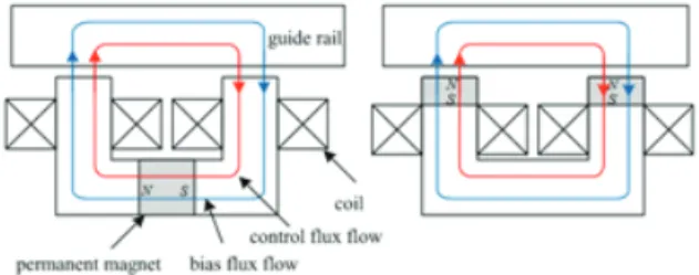
Maglev trains, due to no contact to the guideway, usually provide higher speed and low vibrations and make a great alternative to the railroad transportation. There are three different maglev types: electromagnetic suspension (EMS), electrodynamic suspension (EDS), and hybrid electromagnetic suspension (HEMS) [1]. Since electromagnetic suspension systems have a serious power loss problem, many researchers investigated the hybrid electromagnetic suspension using permanent magnets for possible zero power control [2-5]. These hybrid maglev systems also have some problems since the permanent magnet is located in the control flux path and increase the reluctances in the control flux paths, which results in more flux leakages and requires more currents to produce magnetic forces [6]. Two different types of hybrid maglev systems are shown in Fig. 1.
Fig. 1 U-shaped Hybrid Electromagnetic Suspensions
These U-shaped hybrid maglev systems were analyzed and optimized to reduce the suspension power loss [7-8]. Various design and optimization of U-shaped hybrid maglev
systems were investigated for possible applications on the low speed maglev trains [9]. This paper presents a new C-core type hybrid maglev system. Unlike the classical hybrid maglevs shown in Fig. 1, the new hybrid maglev system has unique flux paths in a manner that the bias fluxes driven by permanent magnets are separated with the control fluxes driven by electromagnets. 1-D circuit model is developed for this new maglev model such that the flux densities and magnetic forces are extensively analyzed.
3-D finite element model is also developed to analyze the performances of the maglev actuators.
2. A New Hybrid Maglev Actuator
Hybrid maglev actuator shown in Fig. 2
consists of a C-core iron assembled with
permanent magnets and dead poles. Two
permanent magnets (PM1 and PM2) located
between the C-core and dead poles direct
bias fluxes to flow through the guide rail and
the opposing C-core pole pair where it
energizes the working air gaps of both
poles.A coil, located at the C-core, provides
control fluxes through the guide rail and the
C-core iron. The control coil is wound in a
manner that control flux is added to the bias
flux at one pole while it is subtracted from
the bias flux at the other pole. The control
flux path of the new maglev actuator has
minimum reluctances only developed by air
gaps of the C-core poles. The upper permanent magnet and the dead pole (PM1 and dead pole 1) can strengthen the bias flux supply to the air gaps of the active poles. The gravity load can be compensated by the static magnetic forces,
and
, generated at the dead poles. The static magnetic force, which is the net force of
and
, can be easily adjusted by changing airgap
at the upper dead pole (dead pole 1) if the gravity load is changed. The opposing pole pair of the C-core in this design helps to generate the bidirectional magnetic forces while the classical hybrid maglev can only generate forces at one direction.
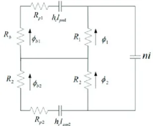
The maglev unit shown in Fig. 2 is represented as a 1-D magnetic circuit if eddy current effects are negligible. The equivalent magnetic circuit for the maglev unit is shown in Fig. 3.
The permanent magnet is represented as
the source
.
and
are the coercive force and the length of the permanent magnet respectively. The total permanent magnet reluctance
is;
(1)
where
and
represent the permeability of the permanent magnet and the face area of the permanent magnet respectively. The reluctances in the air gap j of the poles are;
(2)
,
(3)
(4)
The parameters
,
,
,
, and
represent the permeability of air, the pole
Fig. 2 A New Hybrid Maglev Actuator Model Fig. 3 Equivalent Magnetic Circuit
face area of the active pole, pole face area of dead pole 1, the displacement direction and nominal air gap, respectively. Applying Ampere’s law and Gauss’s law to the radial magnetic circuit leads to a matrix equation.
0 0
0 0 0
1 1 1 1
0 0
0 0
0 0
1 2
2 1 2 1
1 1
2 2 2
2 1
pm c
pm c
b p b
b
p
l h
l i h n R
R R
R R R
R R
(5)
or
(6)
and
,
and
are fluxes, control current, and the number of coil turns, respectively.
The flux densities in the gaps are reduced by flux leakage, fringing, and saturation of magnetic material. The flux density vector is then;
(7)
where
represents flux fringing factor. Magnetic forces developed in the pole plane are described as;
(8)
where the air gap energy matrix is;
(9)
3. Numerical Analysis
3.1 1-D Magnetic Circuit Analysis
The following examples illustrate the 1-D magnetic flux analysis and the resulting magnetic forces for the designed maglev unit.
The designed maglev unit has parameters,
(0.0235 m
2),
(0.008 m),
(1000 turns).
Permanent magnets are also designed to maintain the air gap bias flux density of the C-core active poles at nominal air gap to be 0.75 tesla while they produce static magnetic force of 10000 N to support the gravity load.
The permanent magnet (NdFeB) has parameters
(890000A/m),
(1.1
). Two permanent magnets (PM1 and PM2) have
(0.0223
),
(0.0383
),
(0.05
), and
(0.12
). The dead pole 2 has the same pole face area as pole 1 or pole 2.
The dead pole 1 has pole face area of
(0.0118
) and nominal air gap of
(0.008m). fringing factor
is assumed to be 0.9. The guide rail and C-core iron are assumed to have the same magnetic property.
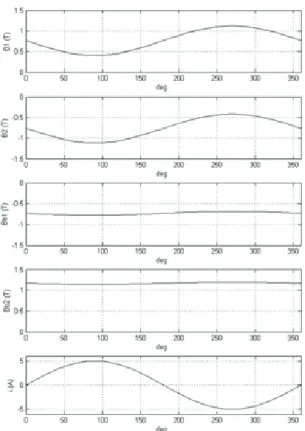
Flux densities in the air gaps and the resulting magnetic forces are simulated on the 1-D magnetic circuit equation. A sinusoidal current of
sin,
∈is applied on the 1-D circuit model. The flux
densities driven with
are calculated by
using Eq. (7) and shown in Fig. 4. Magnetic
forces in Eq. (8) driven with
are shown in
Fig. 5.
Fig. 4 1D flux density simulation with AC currents.
Fig. 5 1D magnetic force simulation with AC currents.
3.2 3D Finite Element Analysis
A commercial magnetic field software (MAXWELL3D) is used to model the new maglev unit. The 3D finite element model of the maglev unit is shown in Fig. 6.
Fig. 6 A New Maglev 3D model
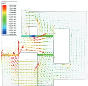
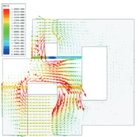
The bias flux density and the resulting magnetic force are calculated using 3-D finite element model at the nominal air gap
,
, and zero control current. Fig. 7
shows the bias flux density distribution for
the maglev unit. The air gap flux densities of
dead pole 2 and pole 2 are 1.2 tesla and
0.74 tesla respectively while the air gap flux
density of dead pole 1 and pole 1 are 0.7
tesla and 0.74 tesla. The resulting magnetic
force on the maglev unit is calculated as
10020 N.
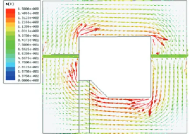
The static magnetic forces are calculated when air gap
is varied from 0.008 m to 0.033 m. Fig. 8 shows the bias flux density distribution with
and
. Fig.
9 shows the static magnetic forces and the corresponding air gap flux densities with changing
. The static magnetic forces are increased up to 12418 N while air gap flux densities are decreased up to 0.68 tesla.
Since the gravity load of the maglev train can be changed with passengers, it is helpful that the static magnetic forces to compensate the gravity load can be adjusted accordingly without changing the nominal air gap
.
The flux densities and the resulting magnetic forces are also calculated at the nominal air gap
,
, control currents of
and
, and are shown in Fig. 10 and Fig. 11. The maximum and minimum magnetic forces with
and
are calculated as 20361 N and 416 N respectively. The full AC magnetic forces are calculated when 36 current sets of,
sin
,
∈are applied on the
Fig. 9 The static magnetic forces and air gapflux densities with Fig. 7 Bias flux density distribution with
A i 0
Fig. 8 Flux density distribution with
,
coil. The calculated magnetic forces are shown in Fig. 12. It is notable that the sinusoidal magnetic forces are very much symmetric about the static magnetic force.
3.3 3D Finite Element Analysis of the Classical Maglev
The classical hybrid maglev unit is
designed as shown in Fig. 13 This hybrid maglev unit is compared with the new maglev unit shown in the previous chapter.
This maglev unit has similar design shown in the previous works [7-8]. The designed hybrid maglev unit has the same parameters as those of the new maglev unit, which are
(0.0235 m
2),
(0.008 m),
(1000 turns).
The bias flux density distribution of the
Fig. 12 Magnetic Forces with sinFig. 10 Flux density distribution with Fig. 11 Flux density distribution with
Fig. 13 A Classical Hybrid Maglev 3D model
hybrid maglev is calculated with zero control current as shown in Fig. 14. The air gap bias flux density and resulting static magnetic force on the maglev unit are calculated as 0.74 tesla and 10004 N respectively. The flux densities and the resulting magnetic forces are also calculated with control currents of
and
as shown in Fig. 15 and Fig. 16. The magnetic forces with
and
are calculated as 16679 N and 5052 N respectively.
The AC magnetic forces are calculated when 36 current sets of
sin,
∈
are applied on the coil. The calculated magnetic forces are shown in Fig.
17. The sinusoidal magnetic forces are not symmetric about the static magnetic force largely due to the quadratic nature of the magnetic force which is proportional to
. This maglev unit can generate magnetic forces only at one direction.
Fig. 14 Flux density distribution with Fig. 15 Flux density distribution with
Fig. 16 Flux density distribution with Fig. 17 The magnetic forces with sin
4. Conclusion
A new C-core type hybrid maglev system is developed. This hybrid maglev system has some advantages over the classical hybrid maglev systems. Unlike the classical hybrid maglev, the new hybrid maglev system has unique flux paths in a manner that the control flux paths have minimum reluctances only developed by air gaps. The currents to produce control fluxes can be considerably reduced with this new design. The static magnetic forces to compensate the gravity load can be adjusted without changing the nominal air gap of the maglev system if necessary.
The new hybrid maglev system is compared with the classical hybrid maglev system. The new maglev system produces larger and more symmetric AC magnetic forces than those of the classical hybrid maglev system when the same currents are applied on both maglev systems. The consumed power to operate this maglev system can be substantially reduced. This new maglev unit may find some applications which require low power operation.
References
[1] Cho, H.-W., Han, H.-S., Lee, J.-M., Kim, B.-S.
and Sung, S.-Y., “Design considerations of EM-PM hybrid levitation and propulsion device for magnetically levitated vehicle,” IEEE Transactions on Magnetics, vol. 45, no. 10, pp.
4632-4635, (2009).
[2] Atherton, D., “Maglev Using Permanent Magnets,”
IEEE Transactions on Magnetics, Vol. 16, No.
1, pp.146-148, (1980).
[3] Morishita, M., Azukizawa, T., Kanda, S., Tamura, N., and Yokoyama, T., “A new Maglev System for Magnetically Levitated Carrier System,” IEEE Transactions on Vehicular Technology, Vol. 38, No. 4, pp.230-236, (1989).
[4] Onuki, T. and Toda, Y., “Optimal design of Hybrid Magnet in Maglev System with Both Permanent and Electro Magnets,” IEEE Transactions on Magnetics, Vol. 29, No. 2, pp.1783-1786, (1993).
[5] Wang, T. C. and Tzeng, Y. K., “A new Electromagnetic Levitation System for Rapid Transit and High Speed Transportation,” IEEE Transactions on Magnetics, Vol. 30, No. 6, pp.4734-4736, (1994).
[6] Lee, H. W., Kim, K. C., and Lee, J., “Review of Maglev Train Technologies,” IEEE Transactions on Magnetics, Vol. 42, No. 7, pp.1917-1925, (2006).
[7] Zhang, Z., She, L., Zhang, L., Shang, C., and Chang, W., “Structural Optimal Design of a Permanent-Electromagnetic Suspension Magnet for Middle-Low-Speed Maglev Trains,” IET Electrical system in Transportation, Vol. 1, No.
2, pp.61-68, (2011).
[8] Liu, S., An, B., Liu, S., and Guo, Z.,
“Characteristic Research of Electromagnetic Force for Mixing Suspension Electromagnet Used in Low-Speed Maglev Train,” IET Electrical Power Applications, Vol. 9, No. 3, pp.223-228, (2015).
[9] Safaei, F., Suratgar, A. A., Afshar, A., and Mirsalim, M., “Characteristics Optimization of the Maglev Train Hybrid Suspension System Using Genetic Algorithm,” IEEE Transactions on Energy Conversion, Vol. 30, No. 3, pp.1163-1170, (2015).
(Manuscript received September 28, 2018;
revised December 19, 2018; accepted January 3, 2019)