Lateral Resistance of CLT Wall Panels Composed of Square Timber Larch Core and Plywood Cross Bands 1
Sang Sik JANG 2,† ⋅Hyoung Woo LEE 2
ABSTRACT
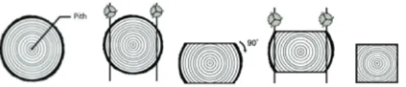
1)Thinned, small larch logs have small diameters and no value-added final use, except as wood chips, pallets, or fuel wood, which are products with very low economic value; however, their mechanical strength is suitable for structural applications. In this study, small larch logs were sawed, dried, and cut into square timbers (with a 90 mm × 90 mm cross section) that were laterally glued to form core panels used to manufacture cross-laminated timber (CLT) wall panels. The surface and back of these core panels were covered with 12-mm-thick structural plywood panels, used as cross bands to obtain three-ply CLT wall panels. This attachment procedure was conducted in two different ways:
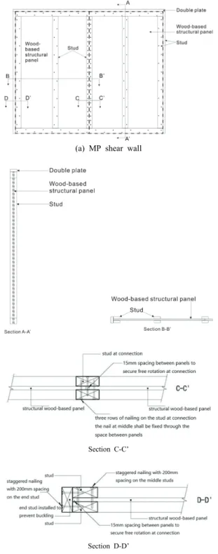
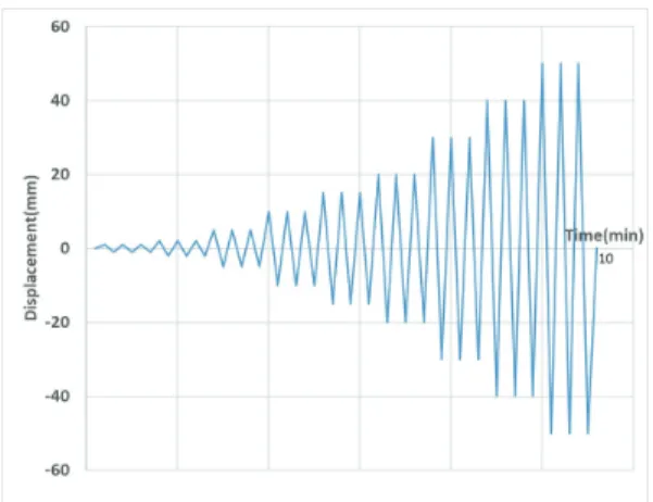
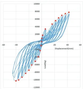
gluing and pressing (CGCLT) or gluing and nailing (NGCLT). The size of the as-manufactured CLT panels was 1,220 mm × 2,440 mm, the same as that of the plywood panels. The final wall panels were tested under lateral shear force in accordance with KS F 2154. As the lateral load resistance test required 2,440 mm × 2,440 mm specimens, two CLT wall panels had to be attached in parallel. In addition, the final CLT panels had tongued and grooved edges to allow parallel joints between adjacent pieces. For comparison, conventional light-frame timber shear walls and midply wall systems were also tested under the same conditions. Shear walls with edge nail spacing of 150 mm and 100 mm, the midply wall system, and the fabricated CGCLT and NGCLT wall panels exhibited maximum lateral resistances of 6.1 kN/m (100%), 9.7 kN/m (158%), 16.9 kN/m (274%), 29.6 kN/m (482%), and 35.8 kN/m (582%), respectively.
Keywords: CLT wall panel, lateral resistance, small square timber, plywood cross band
1. INTRODUCTION
Thinned small larch logs having small diameter do not have specific value-added final use except wood chip, pallet or fuel wood which are products having very low economic value. Even though larch small logs do not have any value-added final usage at present time, their mechanical properties are strong enough to be used for structural purposes (Jang, 2012; Jang, 2015).
In the previous researches (Jang, 2012; Jang, 2015), sawn timbers produced from small larch logs were proved to be strong enough as laminations for structural glulam. In those researches, small larch logs were sawn to square timbers containing pith at centre, which were used as inner-laminations for structural glulam for bending and any laminations for structural glulam for compression. Moreover, in both cases, they showed sufficient structural performance under bending and
1
Date Received June 4, 2019, Date Accepted July 20, 2019
2
Department of Bio-based Materials, College of Agriculture & Life Sciences, Chungnam National University, Daejeon 34134, Republic of Korea
†