HVDC 서브모듈용 커패시터의 고장 분석
Failure analysis of capacitor for sub-module in HVDC
강 필 순
* ★
, 송 성 근**
Feel-soon Kang
* ★
, Sung-Geun Song**
Abstract
In general, capacitors have a large influence on the life of the system due to frequent charging and discharging. In this paper, we analyze the cause of the core failure of high voltage, high current HVDC sub-module film capacitor and analyze the precautions of the capacitor design and manufacturing process. First, the cause of the fault, the failure mode, and the effect are analyzed through the FMEA of the capacitor. To quantitatively evaluate the causes and effects of faults that have the greatest effect on the failure of a capacitor, a fault tree for the capacitor is presented and the failure rate is analyzed according to the design parameters and the driving conditions. It is verified that the main cause of capacitor failure is the capacitance change, and it is necessary to minimize the temperature rise, corona occurrence, electrode expansion, and insulation distance decrease during capacitor design and manufacturing process in order to reduce the failure rate of the capacitor.
요 약
일반적으로 커패시터는 빈번한 충·방전으로 시스템의 수명에 큰 영향을 미친다. 본 논문에서는 고전압, 대전류의 HVDC 서브모듈용 필름 커패시터의 핵심 고장원인을 분석하여 커패시터의 설계 및 제조공정의 주의사항을 분석한다. 먼저 커패시 터의 FMEA 수행을 통해 고장원인, 고장모드, 고장영향에 대해 분석한다. 커패시터의 고장에 가장 큰 영향을 주는 고장원인 과 영향을 정량적으로 평가하기 위해 커패시터에 대한 고장나무(Fault-tree)를 제시하고 설계인자와 구동환경의 조건에 따른 고장률을 분석한다. 커패시터 고장의 핵심 원인이 커패시턴스 변화에 있음을 확인하고, 커패시터의 고장률 저감을 위해서 커 패시터의 설계와 제조공정 중 온도상승, 코로나 발생, 전극팽창, 절연거리 감소를 최소화할 필요가 있음을 검증한다.
Key words : Capacitors, Failure rate, FMEA(Failure Modes and Effect Analysis), FTA(Fault-tree analysis), HVDC (High Voltage Direct Current)
* Dept. of Electronics and Control Engineering, Hanbat National University
** Energy conversion research center, Korea Electronics Technology Institute
★ Corresponding author
E-mail:[email protected], Tel:+82-42-821-1172
※ Acknowledgment
This research was supported by Basic Science Research Program through the National Research Foundation of Korea (NRF) funded by the Ministry of Science, ICT & Future Planning (NRF-2017R1A2B4012154)
Manuscript received Nov. 23, 2018; revised Dec. 10, 2018; Accepted Dec. 11, 2018
This is an Open-Access article distributed under the terms of the Creative Commons Attribution Non-Commercial License (http://creativecommons.org/licenses/by-nc/3.0) which permits unrestricted non-commercial use, distribution, and reproduction in any medium, provided the original work is properly cited.
Ⅰ. 서론
HVDC(High Voltage Direct Current) 시스템 구 성에 있어 서브모듈에 의한 전력변환과 전력공급은
HVDC 시스템의 기본 역할로서 고신뢰성의 서브 모듈 설계와 개발이 요구되며 이를 위해서 서브모 듈을 구성하는 하위 구성품 들에 대한 신뢰성 확보 가 중요하다. 특히 빈번한 충·방전으로 다른 구성
56
품에 비해 상대적으로 수명이 짧은 것으로 알려진 신뢰성 취약 소자인 커패시터의 수명 예측과 고장 률 분석은 서브모듈의 신뢰성 개선을 위해 매우 중 요한 요소이다[1]~[3].
신뢰성이란 시스템 또는 부품이 요구되는 기능을 규정된 조건 하에서 명세된 시간동안 제공하는 확 률을 의미하며 고장률과 수명이 신뢰성의 척도로 사용될 수 있다. 고장률은 부품, 장치, 또는 특정 시 스템이 단위 시간 당 발생하는 고장 횟수이며, 수 명은 고장이 발생할 때까지의 시간으로 정의된다.
수명 예측의 일반적인 방법인 가속수명시험은 시 스템을 구성하는 부품 단위의 고장률을 기반으로 수명을 예측하는 것이 아니라 완제품을 가혹한 환 경에서 가속시험을 통해 실제 운전환경에서의 수 명을 예측하는 방법이다. 이 방법은 가전기기와 같 이 많은 수요가 있는 분야에 활용되고 있지만, 정 확한 수명을 예측하기 위해 다수의 샘플들이 필요 하므로 HVDC 서브모듈과 같은 고가의 시스템에 는 적합하지 않으며, 설계 초기단계에 활용하여 고 장원인, 고장영향 등을 분석하여 설계 또는 제조공 정에 반영하기에는 부적합하다.
본 논문에서는 고전압, 대전류의 HVDC 서브모 듈용 필름 커패시터의 핵심 고장원인을 분석하여 커패시터의 설계 및 제조공정 중의 주의사항을 분 석한다. 먼저 커패시터의 FMEA(Failure mode and effect analysis) 수행을 통해 고장원인, 고장모드, 고장영향에 대해 분석한다. 커패시터의 고장에 가장 큰 영향을 주는 고장원인과 영향을 정량적으로 평가 하기 위해 커패시터에 대한 고장나무(Fault-tree)를 제시하고 설계인자와 구동환경의 조건에 따른 고 장률을 분석한다.
Ⅱ. HVDC용 커패시터의 FMEA와 FTA
본 논문의 분석 대상 커패시터는 높은 안정성, 넓 은 온도범위, self-healing 특성으로 고전압 응용에 적합한 PP(Polypropylene) Metalized Film capacitor (MKP)이다. 일반적으로 필름 커패시터는 개방과 단락의 두 가지 고장 모드를 가진다(간헐적 개방 또는 단락, 고 저항 단락 포함). 이들 커패시터의 고장은 커패시턴스 확산(drift), 온도 불안정성, 높 은 소산인자(dissipation factor) 또는 낮은 절연 저 항에 의해 발생되며, 작동 중 유전체 열화에 따른
전기적, 기계적, 환경적인 과도한 스트레스의 결과 로 나타난다[4]~[7].
2.1 FMEA(Failure Mode and Effect Analysis) FMEA는 시스템, 제품 혹은 공정의 잠재적 고장 모드와 그 영향을 분석하여 잠재적 고장 발생 기회 를 제거하거나 줄일 수 있는 조치를 취하고 이를 문서화하기 위한 체계적인 활동이다. 커패시터(MKP) 의 FMEA를 통해 신뢰성 블록다이어그램에 나타 나는 여러 고장 모드 중 시스템에 가장 큰 영향을 미치는 고장모드를 찾을 수 있다. 수명주기의 초기 단계에서 고장이 많이 발생되는 고장모드를 설계 변경에 의해 미리 제거할 수 있는 장점이 있다.
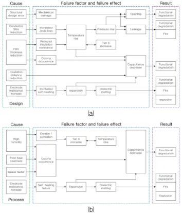
가. 설계 및 제조공정 신뢰성 블록다이어그램 그림 1은 커패시터(MKP)의 설계 및 제조공정 과 정에 대한 신뢰성 블록다이어그램을 나타낸다.
그림 1(a)의 설계관점에서 커패시터(MKP)는 구 조설계, 도체 사이즈, 필름두께, 절연거리, 전극저 항의 설계 오류에 의한 고장의 원인이 존재한다.
설계 관점에서 고장모드는 기구적 손상, 저항손실 증가, 절연저항 감소, 코로나 발생, 자기치유 실패 로 구분할 수 있다. 고장의 영향으로 온도상승, 압 력상승, 전극팽창에 의해 커패시턴스 감소에 따른 기능저하가 발생할 수 있고, 유전체 멜팅에 의한 화재 또는 폭발의 가능성도 존재한다. 특히 커패시 터의 온도상승은 압력상승을 동반하여 누출문제를 발생시켜 화재 발생 가능성을 키우게 되며 소산인 자(tan δ)의 증가, 커패시턴스의 감소를 초래하므 로 커패시터 고장 방지를 위해 매우 중요한 요소 이다.
그림 1(b)는 커패시터(MKP)의 제조공정에 대한 신뢰도 블록다이어그램을 나타낸다. 커패시터 제조 공정 과정에 잠재하고 있거나 이미 알고 있는 고장 모드를 찾아내어 생산 프로세스의 고장으로 인한 영향이나 그 효과를 최소화할 수 있다.
커패시터(MKP)는 제조 공정에 있어 높은 습도, 열처리 불량, 구동환경(Space factor), 전극저항 증 가에 의해 고장이 발생할 수 있다. 제조 공정상의 고장모드는 침식/부식, 코로나 발생, 자기치유 실패 의 고장 모드로 구분할 수 있다.
고장의 영향으로 소산인자(tan δ)의 증가에 따른 온도상승, 커패시턴스의 감소, 자기치유 실패에 따
Failure mode [S] [O] Cause of failure Failure effect
Opening
8 1 Joule loss increases, temperature rise, electrode contact failure § Capacity nonconformity due to capacitance reduction
§ Continuous self-healing
§ Corona occurrence
§ Insulation breakdown 8 2 Defective contact due to heat shrinkage and expansion
8 1 Electrode damage due to vibration and impact
Short
8 3 Temperature rise due to short circuit current and film melting
§ Capacity nonconformity due to capacitance reduction
§ Continuous self-healing
§ Corona occurrence
§ Insulation breakdown
§ Insulation plate and internal filler damage due to insulation breakdown between terminal enclosures 8 3 Decrease in dielectric strength due to film internal pressure decrease
as temperature increases
8 3 Loss of film insulation due to overvoltage
8 1 Decrease of insulation force due to moisture absorption of film 8 1 Decrease in internal pressure of the insulator plate due to high
temperature
8 2 Internal pressure decrease of internal filler occurred at high temperature
Decrease capacitance
5 3 Decrease of internal pressure by high temperature and increase of
self-healing § Capacity nonconformity due
to capacitance reduction
§ Continuous self-healing
§ Corona occurrence
§ Insulation breakdown 5 3 Temperature rise and self-healing increase due to excessive charge
and discharge
5 1 Hydrolysis or scattering of deposited metal by high humidity 5 1 Bus plate damage due to vibration and impact
Dielectric breakdown
8 2 Pollution of insulation by dust § Insulation bushing breakage
due to insulation breakdown between terminal enclosures 8 2 Damage due to vibration and impact
Destruction
of enclosure 7 2 Enclosure damage due to vibration and impact § Enclosure damage
Table 1. Failure mode and effect analysis of MKP.
표 1. 커패시터(MKP)의 고장모드/영향 분석
※ [S]:Severity, [O]:Occurrence
른 전극팽창과 유전체 멜팅에 의한 화재 또는 폭발 의 가능성도 존재한다. 커패시터의 온도상승은 소 산인자(tan δ)의 증가와 서로 밀접한 관련이 있으 므로 온도와 더불어 소산인자의 커패시터 고장 방 지를 위해 매우 중요한 요소이다.
나. 커패시터의 FMEA
커패시터(MKP)의 FMEA는 표 1과 같이 잠재적 고장을 포함하는 고장모드, 심각도(Severity), 발생 도(Occurrence), 고장원인과 고장영향으로 나타낸 다. 고장의 잠재적 원인은 설계 취약성이 요인이고 그 결과가 고장모드이다. 잠재적 고장원인을 파악 하기 위해서는 고장 메커니즘에 초점을 두어야 하 는데 고장 메커니즘은 고장모드로 귀결되는 물리 적, 화학적, 전기적 구조이다. 심각도는 잠재적 고 장모드가 고객에게 미치는 영향의 심각성으로서 고장의 영향에 대해서만 적용되며, 1~10 사이의 값으로 등급을 추정한다.
(a)
(b)
Fig. 1. Influence and result of cause of failure, (a) design perspective, (b) manufacture process perspective.
그림 1. 고장원인별 영향 및 결과, (a) 설계관점,
(b) 제조공정 관점
2.2 커패시터의 고장나무(Fault-tree) 설계
FMEA를 통해 커패시터(MKP)의 고장모드를 개방, 단락, 커패시턴스 감소, 절연파괴, 외함파괴로 구분한 다. 이들 5가지 고장모드 중 가장 중요한 고장모드를 정량적으로 분석하기 위한 고장나무(Fault-tree)를 그 림 2에 나타낸다. FTA는 커패시터(MKP)의 고장 을 고장나무의 최상위 사상으로 하며 바람직하지 않은 사건을 유발할 수 있는 잠재적인 원인이 아래 의 가지로 표현되는 하향식 접근법(top-down)으로 그래픽 표현에서 AND, OR 게이트 등을 사용하여 기본 사상과 최상위 사상 간의 논리적 상호 관계를 표현한다[8], [9].
Fig. 2. Fault-tree of MKP.
그림 2. MKP의 고장나무
그림 2의 고장나무에서 구동환경에 해당되는 사상 (빨간색)은 습도, 과전압, 주파수, 시간, Space factor, 외부요인이며, 설계환경(파란색)에 해당되는 사상 은 구조적 오류, 절연거리감소, 줄(Joule) 손실 증 가, 절연저항감소, 필름두께 감소, 열처리불량, 설계 오류로 분류한다. 고장모드 중 개방, 단락, 커패시 턴스 감소가 주요 분석 대상으로 절연파괴와 외함 파괴는 Others로 묶어 분석한다.
그림 3은 구동환경과 설계인자의 고장률을 모두 동일하게 0.001부터 0.23[Failures/106Hours]까지 변 화시켜 MKP의 고장모드인 [Open], [Short], [Capacitance decrease], [Others]에 의한 고장률의 추이를 분석 한 결과를 보여준다. 최상위 사상은 [Capacitance decrease] - [Short] - [Open] - [Others]의 순으로
나타나며, 커패시턴스 감소가 전체 고장률에 가장 큰 영향을 미치게 된다.
Fig. 3. Variation of failure-rate when the failure rate of the basic event of the driving environment and the design factor is given equally.
그림 3. 구동환경과 설계인자의 기본 사상의 고장률이 동 일하게 주어진 경우의 고장률 변화
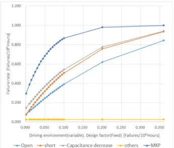
Fig. 4. Variation of failure-rate when the failure rate of the design parameter is constant.
그림 4. 설계인자의 고장률이 일정한 경우 구동환경의 고 장률 증가에 따른 고장률 변화
그림 4는 구동환경에 해당되는 습도, 과전압, 주 파수, 시간, Space factor, 외부요인의 변화가 전체 고장률에 미치는 영향을 파악하기 위하여 설계인
자를 0.025[Failures/106Hours]로 고정한 상태에서 구동환경 조건을 0.001~0.36[Failures/106 Hours]
까지 변화시켜 MKP의 고장모드인 [Open], [Short], [Capacitance decrease], [Others]에 의한 고장률의 변화를 나타낸다.
Fig. 5. Variation of failure-rate when the failure rate of the driving environment is constant.
그림 5. 구동환경의 고장률이 일정한 경우 설계인자 고장 률 증가에 따른 고장률 변화
최상위 사상인 MKP의 고장은 [Capacitance decrease]
- [Short] - [Open] - [Others]의 순으로 영향을 끼 침을 알 수 있다. 이 경우에도 커패시턴스 감소의 영향이 전체 고장률에 가장 큰 영향을 미침을 확인 할 수 있다.
그림 5는 구조적 오류, 절연거리감소, 줄(Joule) 손실 증가, 절연저항감소, 필름두께 감소, 열처리불 량, 설계오류의 설계환경의 변화가 전체 고장률에 미치는 영향을 파악하기 위하여 구동환경 조건을 0.025[Failures/106Hours]로 고정한 상태에서 설계 인자 조건을 0.001~0.44[Failures/106Hours]까지 변화시켜 MKP의 고장모드인 [Open], [Short], [Capacitance decrease], [Others] 요인에 의한 고 장률의 변화를 나타낸다. 설계인자의 변화가 커패 시턴스 감소에 큰 영향을 주며 전체 고장률에 반영 됨을 확인할 수 있다. 최상위 사상인 MKP의 고장 은 [Capacitance decrease] - [Short] - [Open] - [Others]의 순으로 영향을 끼침을 보이고 있으며, 커패시턴스 감소의 영향이 전체 고장률에 가장 큰 영향을 미치게 된다.
(a)
(b)
(c)
(d)
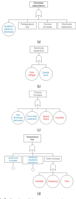
Fig. 6. Configuration of low events occurring capacitance rise, (a) capacitance rise, (b) electrode expansion, (c) corona increase, (d) temperature rise.
그림 6. 커패시턴스 변화 사상에 대한 하위 사상 구조, (a) 커패시턴스 감소, (b) 전극팽창,
(c) 코로나 발생, (d) 온도상승
그림 6은 MKP의 고장률에 가장 큰 영향을 미치는 [Decrease capacitance] 사상에 대한 하위 사상 구조를 보여준다. [Decrease capacitance] 사상은 [Electrode expansion], [Corona increase], [Temperature rise]
과 같이 하위에 원인 사상을 갖는 경우와 설계 과정 에 고려할 수 있는 [Isolation distance decrease] 사 상을 가짐을 그림 6(a)에서 알 수 있다. 그림 6(b)의 [Electrode expansion] 사상은 [Over voltage] 구동환
경을 정격 범위 내에서 사용하거나 설계 조건인 [Design error]의 최소화를 통해 발생률을 최소화 할 수 있다.
그림 6(c)의 [Corona increase] 사상은 필름 두께 감소, 열처리 불량의 설계와 제조공정을 통해 최소화 가능하며, [Space factor]와 [Humidity]의 구동환경의 개선을 통해 발생률의 저감이 가능하다. 그림 6(d)의 [Temperature rise] 사상은 [Decrease capacitance] 발생에 가장 큰 영 향을 미치는 사상으로 설계 중 [Joule loss increase]와 [Reduced insulation resistance]를 고려하고 손실계수 인 [Tan δ increase]를 방지하여 고장 발생을 저감시킬 수 있다. [Tan δ increase] 사상은 습도, 주파수, 시간의 하위 사상에 의해 발생률이 변하게 되는데, 주파수와 시간에 의한 영향 보다는 습도에 의한 영향이 크다.
커패시터(MKP) 고장은 [Decrease capacitance]
사상의 영향이 가장 크며 환경적으로 가장 중요한 요소는 온도상승으로 커패시터는 유전체 상수, 유 전체 재료의 팽창 또는 수축으로 인해 온도에 따라 커패시턴스 값이 변하게 된다. 커패시터 온도가 증 가하면 전자 활동의 증가로 절연 저항이 감소하고 과도한 습기에 장기간 노출된 권선은 낮은 절연 저 항을 가질 수 있다. 온도 증가에 따라 커패시터의 물리적 또는 전기적 특성의 변화를 일으키는 유전 체 물질의 화학적 활성이 증가하여 절연내력 (유전 체 내전압 또는 전압스트레스)은 감소하므로 주의 하여야 한다.
Ⅲ. 결론
본 논문에서는 HVDC 서브모듈용 필름 커패시터 (MKP)의 주요 고장원인을 분석하여 커패시터의 설계 및 제조공정의 주의사항을 분석하였다. 커패 시터의 FMEA 수행을 통해 고장원인, 고장모드, 고 장영향에 대해 분석하였다. 커패시터의 고장에 가 장 큰 영향을 주는 고장원인과 영향을 정량적으로 분석하기 위해 커패시터의 고장나무(Fault-tree)를 이용하여 설계인자와 구동환경의 조건에 따른 고 장률을 분석하였다.
커패시터 고장은 커패시턴스 변화(Capacitance decrease)에 크게 영향을 받음을 확인하였고, 커패 시터의 고장률 저감을 위해서는 커패시터의 설계와 제조공정 중 온도상승, 코로나 발생, 전극팽창, 절연 거리 감소를 최소화할 필요가 있음을 확인하였다.
References
[1] Eui Min Choi, “Reliability factor and reliability evaluation method of power electronic system,”
Journal of power electronics, vol.23, no.3, pp.34-40,
2018.[2] S. Yang, A. Bryant, P. Mawby, D. Xiang, L.
Ran, and P. Tavner, “An industry-based survey of reliability in power electronics converters,”
IEEE Trans. Industry Applications, vol.47, no.3,
pp.1441-1451, 2011. DOI:10.1109/TIA.2011.2124436 [3] Jun Seok Lee, “Power conversion system life evaluation technology,” Journal of power electronics, vol.23, no.3, pp.41-47, 2018.[4] Film Capacitors: General technical information, TDK, 2015.
[5] Y. Tang, L. Ran, O. Alatise, and P. Mawby,
“Capacitor Selection for Modular Multilevel Converter,” IEEE Trans. on Industry Applications, vol.52, no.4, pp.3279-3293, 2016.
DOI:10.1109/TIA.2016.2533620
[6] Vishay Roederstein, “Film capacitors, General Technical Information,” http://www.vishay.com [7] KEMET, “Power Electronics Film Capacitors,”
http://www.kemet.com
[8] Military Handbook, Reliability Prediction of Electronic Equipment, 1991.
[9] Failure Mode/Mechanism Distributions (FMD-97), Reliability Analysis Center, 1997.
BIOGRAPHY