- 676 -
해석적인 방법을 이용한 Cogging Torque 저감을 위한 영구자석형 전동기 형상 설계
방량, 이병화, 홍정표 한양대학교
Cogging Torque Reduction Design of Permanent Magnet Motor Using Analytical Method
Liang Fang, Byeong-Hwa Lee, Jung-Pyo Hong Hanyang University
Items of PMSM model Value [mm] Items of PMSM model Value [mm]
Inner radius of stator Length of air-gap
Outer radius of rotor Length of stack
Inner radius of PM Slot opening width
Abstract — In this paper, an analytical method used for predicting the magnetic field distribution and cogging torque characteristic in a permanent magnet synchronous motor (PMSM) is presented. The magnetic field is analyzed with the space harmonic analysis, and the cogging torque is calculated based on the air-gap field distribution and slot-opening effect considered by relative permeance. The validity of the presented analytical method is confirmed by 2-dimensional finite element analysis (FEA). Then this analytical method combines with response surface methodology (RSM) is applied to the prototype PMSM model rebuilding in order to minimize the cogging torque. Finally, an optimized PMSM model is built and the cogging torque reduction is confirmed by FEA.
1. INTRODUCTION
Cogging torque results from the interaction between permanent magnet and slotted iron structure and exists in almost all type permanent magnet motors [1]. Cogging torque is produced since the non-constant flux density distribution in the air-gap field. It is the circumferential component of attractive force that attempts to maintain the alignment between the magnets and the stator tooth [2]. As a kind of pulsation torque, the cogging torque adds ripple component to the desired constant output torque, and results in vibration and noise [2]. Therefore, the cogging torque reduction in PM motor has practical significance. Compare with 2-dimensional (2-D) finite element analysis (FEA), the analytical method can analyze motor characteristics very fast according to the variation of any design parameters. It will alleviate the iterative work in motor design. Therefore, in this paper, an analytical method is presented for cogging torque analysis in PM motor design.
2. ANALYTICAL METHOD 2.1 Analysis Model
The prototype analysis model is shown in Fig. 1. It is a surface type 4-pole/18-slot PMSM model. TABLE 1 lists the specification.
2.2 Assumptions in Analytical Method
In order to simplify the magnetic field calculation, the following assumptions are made first [2]:
a). the permeability of the iron is infinite, i.e. ∞, b). the slots area are simplified to a rectangular shape;
c). magnetic field distribution is determined from the product of the magnetic field produced by magnets and relative permeance;
d). the magnetic field developed by the magnets is obtained from a 2-D solution by assuming a slotless stator surface;
e). the air-gap permeance is calculated according to an assumed field pattern, as shown in Fig. 2.
TABLE 1 SPECIFICATION OF PROTOTYPE PMSM MODEL
Ro
Ri Rs Rm
rotor stator
Ro
Ri Rs Rm
rotor stator
<Fig. 1> Configuration of prototype PMSM model 2.2.1 Air-gap Field Prediction Using Analytical Method The magnetic field due to magnet is obtained from equivalent magnetization, and radial component of flux density in air-gap is obtained from Poisson’s equation [1]:
{ } { ( ) }
( 1) 1,3,5... 2
2 1 1 2
2 2 2 2 2
4 cos
( ) 1
( 1) 2 ( 1)
1 1
np
n i
magnet
n r o
np np np np
o m o m
np np np np np
r r
i m o i m o
r r
M np R
B np
R np
np R R R np R
R R R R R R
μ θ
μ μ
μ μ
∞ −
=
+ −
⎛ ⎞
= ⋅ ⎜ ⎟ ⋅
− ⎝ ⎠
⎡ ⎤
⎢ − + − + ⎥
⎢ ⎥
⋅⎢⎢⎣ + − − − − ⎥⎥⎦
∑
(1)
and 1,3...
2 cos and sin
2 2
p p
n n r p
n
n n
M M np M B α π α π
θ α
∞
=
⎛ ⎞
= = ⎜ ⎟
⎝ ⎠
∑
where, n is order of space harmonic, p is pole pairs, is relative recoil permeability of PM, is remanence, and is ratio of pole-arc to pole pitch of PM.
2.2.2 Relative Permeance for Slot-opening Consideration The stator slot openings influence the flux density distribution in the air-gap field. According to assumption (e), the main flux passes radially across the air-gap and takes circular trajectories into the slot openings, as Fig. 2 illustrates, which result in the non-constant flux density distribution along stator tooth side surface. The effect of slot opening is dealt with "relative permeance" method. The permeance
and relative permeance is calculated according to the effective flux path length between rotor and stator approximately from [2],
$
0
0
and 2
4
m s
r m r
h r
g g h
μ λ
λ π λ μ
μ μ
= =
⎛ ⎞
+ + ⎜⎝ + ⎟⎠ (2) for ≤ ≤ , ; ;
is the pole pitch; is the slot pitch; is magnets height.
<Fig. 2> Simplified model of slot effect on flux distribution 2009년도 대한전기학회 하계학술대회 논문집 2009. 7. 14 - 17
- 677 -
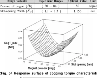
Design variables Experiment Ranges Optimal Value Unit Pole-arc of magnet [] ( 80 ~ 84 ) 82 degree Slot-opening Width [] ( 1.1 ~ 1.3 ) 1.156 mm 2.2.3 Flux Density and Cogging Torque Calculation
The flux density on the surface of the stator slot bore is calculated according to assumption (c). It is expressed as the product of flux density produced by PM and relative permeance [2],
( ) $( )
rb x magnet
B =B ⋅λ x (3) Then, according to the non-constant flux density distribution along the sides of tooth in one slot region, the cogging torque at any rotor position, is calculated as following[2],
0
1 2 1 2
2 2 2 2 2
1 2 0 1 0 2 0
s s
Q Q b
rb rb rb rb
c a t a t s
k toothside k
B B B B
T l r dy l r dr
μ μ
= =
′ ′
⎛ − ⎞ ⎛ − ⎞
=∑ ∫ ⎜⎜⎝ ⎟⎟⎠ =∑ ∫⎜⎜⎝ ⎟⎟⎠ (4)
where is the effective radius of cogging torque, is the slot opening width, is the slots number, is stack length.
Then, the presented analytical method is verified by comparing the results of analytical calculation and FEA. Fig. 3 and Fig. 4 show the comparisons of predicted flux density distribution in the air-gap and cogging torque produced in PMSM. The accuracy of this analytical method is verified by a good agreement of analytical method and FEA results. So, to instead of the time-consuming FEA, the magnetic field and cogging torque characteristics in PMSM can be well analyzed using this validated analytical method.
<Fig.3> Flux density results comparison
0 1 2 3 4 5 6 7 8 9 10
-0.15 -0.10 -0.05 0.00 0.05 0.10 0.15
Cogging Torque (Nm)
Mechanical Angle(DEG.) FEA Analytical
<Fig. 4> Cogging torque results comparison 2.3 Cogging Torque Reduction Design
By performing the confirmed analytical method, the cogging torque characteristic in surface type PMSM can be examined easily, according to the variation of PM pole-arc and slot-opening width.
In this paper, a well recognized optimization method, response surface methodology (RSM), is used to analyze the cogging torque reduction. TABLE 2 lists the design variables and their experiment ranges for performing RSM. In the region, the data required to make approximation polynomial model is obtained by using the analytical method in central composite design [3]. The model shows the relationship between cogging torque and design variables as:
2 _ m a x
2
ˆ 2 2 .6 9 0 .5 5 0 .1 9 0 .0 0 3
0 .1 3 0 .0 0 1
c o g
Y P a S w P a
S w P a S w
= − − +
+ − (5)
where is pole-arc of PM, and is slot-opening width.
TABLE 2 Design variables and optimal results by RSM
<Fig. 5> Response surface of cogging torque characteristic
0 5 10 15 20 25 30 35 40 45
0 1 2 3 4 5 6 7 8 9 10
Output Torque (Nm)
Mechanical Angle (Deg.) Optimized model Prototyep model
<Fig. 6> Output torque characteristic comparison Fig. 5 shows the response surface of cogging torque drawn by equation (5). The optimal point, of that cogging torque minimized at 82 and 1.156[mm], respectively. In the optimal point, the cogging torque is 0.007[Nm], and the result has decreased 95.3[%] than that of the prototype. In addition, output torque characteristic comparison between optimal and prototype models is shown in Fig. 6. The result confirmed that the torque performance of optimal model is improved as cogging torque reduction. The presented analytical method is successfully applied to the optimization design of cogging torque reduction in PMSM.
3. Conclusion
In this paper, an analytical method used for predicting the magnetic field distribution in the air-gap field of a surface type PM motor is presented. According to the flux distribution in stator slot region, the cogging torque characteristics are analyzed. The accuracy of the analytical method is well verified by a good agreement of results comparison with FEA. Then, with the confirmed analytical method, the output torque ripple reduced by minimizing the cogging torque is achieved by optimizing the magnet pole-are and slot opening width in an PMSM. The advantages of analytical method on simple modeling process and instant calculation is emphasized.
[Reference]
[1] Z. Q. Zhu, D. Howe, "Analytical prediction of the cogging torque in radial-field permanent magnet brushless motors," IEEE Trans. Magn., vol. 28, no. 2. pp1317-1374.
[2] Z. Q. Zhu, "Instantaneous magnetic field distribution in brushless permanent magnet dc motors. Part 3, Effect of stator slotting," IEEE Trans. Magn., vol. 29, pp. 143-151, Jan. 1993.
[3] Sung-Il Kim, Ji-Young Lee, Young-Kyoun Kim, Jung-Pyo Hong, Hur, Y., Yeon-Hwan Jung, "Optimization for reduction of torque ripple in interior permanent magnet motor by using the Taguchi method," IEEE Trans. Magn., vol. 41, pp. 1796-1799, May 2005.