≪연구논문≫ Journal of the Korean Magnetics Society, Volume 22, Number 2, April 2012 http://dx.doi.org/10.4283/JKMS.2012.22.2.045
− 45 −
피드백형 플럭스게이트 마그네토미터 제작
손대락*
한남대학교 물리학과, 대전시 대덕구 오정동 133, 306-791
(2012년 2월 19일 받음, 2012년 3월 14일 최종수정본 받음, 2012년 3월 19일 게재확정)
Co계 비정질 리본인 Metglass®2714A 코어를 사용하여, 자기장 측정 범위가 ± 100 µT, 측정 주파수 범위가 dc~10 Hz인 3-축의 피드백형 플럭스게이트 마그네토미터를 제작하였다. 제작된 마그네토미터의 아날로그 출력의 전기잡음은 5 pT/ at 1 Hz 이 었으며, Micro-controller와 24 bit ADC(Analog to Digital Converter)를 사용한 마그네토미터의 출력을 0.1 nT의 분해능으로 디지 털로 출력 할 수 있게 하였다. 디지털 신호로 출력되는 마그네토미터의 선형도는 1 × 10⁻⁴이하였으며, 1시간 동안 영점 변화는 0.2 nT 이하였다.
주제어 : 마그네토미터, 저자기장측정, 비정질코어, 플럭스게이트, 자기센서
I. 서 론
플럭스게이트 마그네토미터(flux-gate magnetometer)는 1930대에 개발되어 오늘날까지 사용되고 있는 저자기장 측정 장치 중 하나이다[1]. 플럭스게이트 마그네토미터의 원리는 코 어에 교류자기장을 충분히 세게 인가하여 코어를 포화자화시 킨 후, 측정하고자하는 외부자기장(피측정 자기장)이 코어에 인가될 경우 포화자화에 도달하는 시간이 비대칭으로 변화하 게 되고, 이 시간 차이에 의한 자속의 변화를 이용하여 피측 정 자기장을 측정하게 된다[2]. 플럭스게이트 마그네토미터에 사용되는 연자성 코어가 비선형의 자기특성을 가지고 있기 때 문에 플럭스게이트 마그네토미터의 선형도가 일반적으로 수%
정도이다. 이를 개선하는 방법으로 피드백의 원리를 사용하여 2차 코일에 피측정 자기장과 크기가 같고 방향이 반대인 자 기장을 인가하여 실제적으로 플럭스게이트 마그네토 미터의 코어가 받는 피측정 자기장이 0이 되게 하는 방법이다. 이 경우 선형도가 0.01 % 이상을 얻을 수 있으며, 마그네토미터 의 장기적 안정도(long-term stability)도 향상된다.
본 연구에서는 플럭스게이트 마그네토미터 코어에 유도되 는 기전력의 2차 고조파성분만을 증폭하고 저주파대역증폭기 를 통과한 전압신호를 피드백을 시키는 방식의 플럭스게이트 마그네토미터를 제작하고 그 특성을 측정하였다.
II. 플럭스게이트 마그네토미터 제작
마그네토미터에 사용되는 코어는 Co계 비정질 리본 Metglass®2714A를 폭이 3 mm 되게 슬리팅 한 후 300oC에
서 1시간 열처리한 코어를 사용하였다[3]. 코어를 자화시키는 일차 코일은 Fig. 1에서와 같이 2개로 나누어 직경 0.2 mm 의 에나멜 동선을 사용하였다. 열처리를 한 비정질 리본은 2개 의 코일포머에 교대로 10회 감았다. 피측정 자기장에 의한 자 속변화를 측정하고 피측정 자기장을 보상하기 위한 코일은 직 경이 8 mm, 길이가 45 mm인 원형 보빈에 직경이 0.12 mm인 에나멜 동선을 600회 권선하였다.
마그네토미터의 전자회로도가 Fig. 2에 주어져 있다. 디지 털 계수기로부터 나오는 자화주파수 f 신호를 전력증폭기로 전력증폭하여 코어를 자화시키고, 이차 코일에 유도되는 교류 성분의 신호만을 통과시키기 위하여 축전기를 거친 후 CMOS switch를 사용한 demodulator에 입력되어 2f 신호의 성분을 검출 한 후 10 Hz 대역의 저주파 대역 필터(LPF)를 사용하였다. LPF의 출력 전압은 피드백(feedback) 증폭기를 거처 2차 코일에 입력되어, 코어가 받는 실제 자기장이 0 이 되게 하였다. 이때 이차코일에 가해주는 전압이 피측정 자기 장에 비례하기 때문에 이 기전력을 24 bit의 delta-sigma ADC (Analog to Digital Converter)를 사용하여 마그네토미터의
Hz
*Tel: (042) 629-7512, E-mail: [email protected]
Fig. 1. (Color online) Photography of the constructed flux-gate sensor.
− 46 − 한국자기학회지 제22권 2호, 2012년 4월
출력을 0.1 nT 의 분해능으로 디지털 신호로 변환하여 컴퓨 터와 RS422 serial 통신을 할 수 있게 하였다. 3축의 ADC 를 제어하고 PC와 통신을 하게하는 micro-controller는 Atmel사의 ATMEGA8을 사용하였다. Fig. 3은 본 연구에서 제작된 플럭스 게이트 마그네토미터의 사진이다. 왼편은 마그
네토미터의 앞면으로 analog PCB를 보여주고 있으며, 오른편 은 마그네토미터의 뒷면으로 디지털 PCB를 보여주고 있다.
III. 마그네토미터의 특성 측정
제작된 플럭스게이트 마그네토미터의 교정은 Fig. 4와 같이 비자성실험실에 위치한 3-축의 Helmholtz코일을 사용하여 측 정범위(full scale)가 ± 100 µT되게 교정을 한 후 선형도,
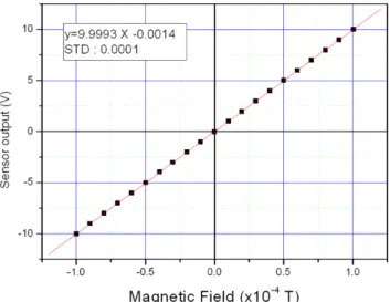
noise 특성 및 장시간 영점의 안정도를 측정하였다. 마그네토
미터의 선형도 측정 결과는 Fig. 5와 같이 선형도가 1 × 10⁻⁴ 이하였다. 마그네토미터의 noise 특성과 영점의 안정도 특성 Fig. 2. (Color online) Schematic diagram of the 3-axis flux-gate magnetometer.
Fig. 3. (Color online) Photography of the constructed 3-axis flux-gate magnetometer; left hand side shows analog PCB and right hand side shows digital PCB.
Fig. 4. (Color online) Photography the 3-axis Helmholtz coil in non- magnetic laboratory used for calibration of the developed flux-gate magnetometer.
≪연구논문≫ 피드백형 플럭스게이트 마그네토미터 제작 − 손대락 − 47 −
측정은 자기차폐(magnetic shielding)장치 안에 센서를 놓은 후 측정을 하였다. Noise spectrum 측정은 마그네토미터의 아날로그 출력을 신호분석기(HP35670A)를 사용하여 분석하 였으며, 주파수 범위가 dc~12.5 Hz에서 800 lines을 10번 rms평균을 측정한 결과가 Fig. 6과 같으며, 1 Hz에서 noise 가 5 pT/ 정도였다. Fig. 7은 마그네토미터의 디지털 출 력을 자기차폐 장치안에서 5000 sec 동안의 안정도를 측정한 결과로 전원을 공급한 후 1000 sec 정도가 경과되면 안정되 었으며, 그 후 4000 sec 동안은 드리프트(drift)가 0.2 nT 이 하였다.
IV. 결 론
본 연구에서는 Co계 비정질 리본인 Metglass®2714A 코어 를 사용하여, 자기장 측정 범위가 ± 100 µT, 측정 주파수 범 위가 dc~10 Hz인 3-축의 피드백형 플럭스게이트 마그네토미 터를 제작하였다. 측정신호를 디지털로 출력하기 위하여 micro-controller와 24 bit ADC를 사용 마그네토미터의 출력 을 0.1 nT의 분해능으로 출력 할 수 있게 하였다. 제작된 마 그네토미터를 교정하기 위하여 비자성 실험실에 위치한 3-축 의 Helmholtz 코일을 사용 하였으며, 전기잡음과 마그네토미 터의 영점 안정도를 측정하기 위하여 µ-메탈로 제작된 자기 차폐장치를 사용하였다. 제작된 마그네토미터의 아날로그 출 력의 전기잡음은 5 pT/ at 1 Hz 였으며, 디지털 신호로 출력되는 마그네토미터의 선형도는 1 × 10⁻⁴이하였으며, 1시 간 동안 영점 변화는 0.2 nT 이하였다.
감사의 글
본 연구개발을 위하여 2011년 한남대학교 학술연구조성비 에 의하여 일부 지원되었으며, 이에 감사드립니다.
참고문헌
[1] W. Goepel, J. Hesse, and J. N. Zemel, Sensors Vol. 5 Magnetic Sensors, VCH, Weinheim (1989) pp. 154~203.
[2] D. Son, J. Kor. Mag. Soc. 16, 182 (2006).
[3] Y.-J. Kim, D. Son, and D.-H. Son, J. Kor. Mag. Soc. 11, 134 (2001).
Hz
Hz
Fig. 7. (Color online) Long-term stability of the developed flux-gate magnetometer.
Fig. 5. (Color online) Linearity of the developed flux-gate magnetometer.
Fig. 6. (Color online) Noise spectrum of the developed flux-gate magnetometer.
− 48 − 한국자기학회지 제22권 2호, 2012년 4월
Construction of Feed-back Type Flux-gate Magnetometer
Derac Son*
Department of physics, Hannam University, 133 Ojung dong, Daejeon 306-791, Korea (Received 19 February 2012, Received in final form 14 March 2012, Accepted 19 March 2012)
Feed-back type 3-axis flux-gate magnetometer using Co-based amorphous ribbon (Metglass®2714A) was constructed in this work.
Measuring range of magnetic field and frequency were ± 100µT and dc~10 Hz respectively. For the interface to computer, micro- controller and 24 bit ADC (Analog to Digital Converter) were employed and resolution of digital output was 0.1 nT. Magnetometer noise of analog output was 5 pT/ at 1 Hz. Digital output of the magnetometer showed linearity of 1 × 10⁻⁴ and the offset drift was smaller than 0.2 nT during 1 h.
Keywords : magnetometer, low magnetic field, amorphous core, flux-gate magnetometer, magnetic sensor Hz