• 검색 결과가 없습니다.

Determining the Refractive Index and Three-Dimensional Shape of an Optical Component using Digital Holographic Microscopy with Liquid

N/A
N/A
Protected

Academic year: 2021

Share "Determining the Refractive Index and Three-Dimensional Shape of an Optical Component using Digital Holographic Microscopy with Liquid"

Copied!
5
0
0

로드 중.... (전체 텍스트 보기)

전체 글

(1)

137

Determining the Refractive Index and Three-Dimensional Shape of an Optical Component using Digital Holographic Microscopy with Liquid

Sanghoon Shin

1

and Younghun Yu

2

1

KPS, DongTan Myon, Hwasung 445-811, Korea

2

Department of Physics, Jeju National University, Jeju 690-756, Korea

(Received April 17, 2014; Revised manuscript May 13, 2014; Accepted May 21, 2014)

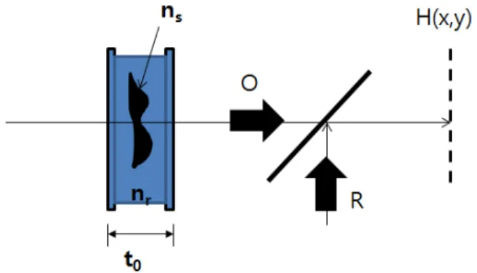
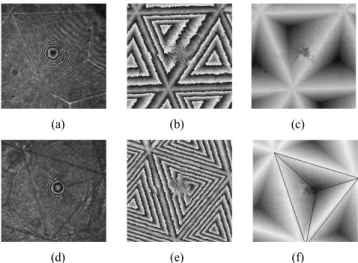
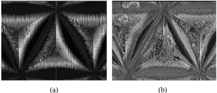
In this study a method is proposed for measuring both the refractive index and the shape of a transparent object. The proposed method combines a digital holographic microscope with a liquid. The holograms of a sample immersed in different liquids are recorded and then the three-dimensional phase information of the sample is reconstructed numerically. In particular, we have proposed a theoretical model for determining both the refractive index and shape of a sample, and micro-corner cubes are examined experimentally.

Keywords: Holography, Digital holography, Corner cube

OCIS codes: (090.0090) Holography; (090.1760) Computer holography; (070.0070) Fourier optics and signal processing

액체와 DHM을 이용한 소형 광학부품의 굴절률 및 형상측정

신상훈

1

ㆍ유영훈

2

1

KPS

445-811 KPS, 경기도 화성시

2

제주대학교 물리학과

690-756 제주시 아라1동 1번지

(2014년 4월 17일 받음, 2014년 5월 13일 수정본 받음, 2014년 5월 21일 게재 확정)

디지털 홀로그래피 현미경은 기준광과 시료의 굴절률과 두께에 의한 물체광의 광 경로차를 측정하여 3차원 형상을 측정하는 방법이다. 대량 생산을 위해 사용되는 사출방법을 이용한 광학제품은 공정 조건에 의해 굴절률과 같은 물성이 변화한다. 소형 사출 광학제품의 정확한 광학적 기능을 디자인하기 위해서는 물질의 굴절률과 3차원 형상을 정확히 측정 할 필요가 있다. 본 연구에서는 2개의 액체와 투과형 디지털 홀로그래피 현미경을 이용하여 사출된 소형 코너 큐브의 굴절률과 3차원 형상을 측정하 는 연구를 하였다.

Keywords: 홀로그래피, 디지털 홀로그래피, 코너큐브

OCIS codes: (090.0090) Holography; (090.1760) Computer holography; (070.0070) Fourier optics and signal processing

† E-mail: [email protected]

Color versions of one or more of the figures in this paper are available online.

I. 서 론

현대 금형기술의 발전으로 소형 광학부품을 대량으로 사출 하여 사용하고 있다. 이로 인해 광학기기의 값이 매우 싸지 고, 비구면 사출에 의해 기기의 크기도 작아지는 장점이 있 다. 이러한 사출 과정에서 광학기기의 3차원 형상을 제조하 기 위해 열을 가한다. 열을 가하고 냉각하는 과정에서 물질 의 굴절률이 변화 된다.

[1, 2]

사출 광학기기가 정확한 광학적

작용을 위해서는 광학기기 물질의 굴절률과 형상이 디자인 값과 일치하여야 한다. 그러므로 사출 광학기기의 정확한 굴 절률 값과 3차원 형상 측정이 필수적이다.

굴절률 측정 방법은 많이 알려져 있다 .

[3-12]

그 중 가장 정 밀하게 측정 할 수 있는 방법은 편광해석법 (ellipsometry) 방 법과 간섭을 이용하는 방법이다 . 일반적인 편광해석법방법과 간섭방법은 시료의 한 위치에서 굴절률을 측정한다 . 시료의 2차원 굴절률 측정을 위해서는 2차원 스캐닝 방법을 이용하

DOI: http://dx.doi.org/10.3807/KJOP.2014.25.3.137 ISSN : 2287-321X(Online)

(2)

FIG. 1. Shematic diagram of Digital holography microscope with immersion liquid. R: Reference Beam, O: Objective Beam, BS:

Beam Splitter, H(x, y): Hologram plane,

; refractive index of sample,

; refractive index of immersion liquid,

; thickness of immersion liquid.

여 정밀한 2차원 굴절률 측정을 할 수 있다. 그러나 2차원 스캐닝 방법을 이용한 굴절률 측정 방법은 측정 시간이 매우 긴 단점이 있다. 근래에 간섭 방법 중 2차원 스캐닝 방법을 이용하지 않고 한번에 2차원 위상정보를 알 수 있는 DHM (Digital Holographic Microscopy) 방법이 개발되고 많이 연 구 되었다.

[13-14]

DHM 방식은 CCD(Charge Coupled Device) 와 같은 반도체 기록 장치를 이용하여 실시간으로 측정 대상 체의 홀로그램 데이터를 획득하고, 수치적 3차원 영상 재생 의 방법으로 측정 대상 체의 3차원 데이터를 획득하는 방법 이다. 그러나 디지털 홀로그래피도 간섭을 이용하기 때문에 물체의 단차가 사용된 파장(λ) 보다 큰 물체의 측정에는 한 계가 있다. 이러한 한계를 극복하기 위하여 2파장 디지털 홀 로그래피가 제안 되었다.

[15-17]

그러나 2파장 디지털 홀로그래 피는 2파장 각각에 대하여 홀로그램을 얻고 이를 수식적으 로 재생하는 과정이 복잡한 단점이 있어 굴절률 차이를 이용 하여 광 경로차(optical pass difference)를 작게 하여 측정하 는 방법이 제안 되었다.

[18, 19]

일반적으로 투과형 방법을 이 용하여 3차원 측정을 위해서는 물질의 굴절률을 정확히 알 아야 측정할 수 있다. 또한 정확한 굴절률 측정을 위해서는 정확한 형상정보를 알아야 한다.

본 논문에서는 굴절률이 다른 2개의 액체와 투과형 DHM 을 이용하여 시료의 형상정보와 굴절률 정보를 모르는 경우, 사출된 소형 코너큐브의 굴절률 값과 3차원 형상을 동시에 측정 하는 방법에 대하여 연구하였다.

II. 이론적 배경

디지털 홀로그래피 현미경에서 홀로그램 데이터는 CCD로 입력되는 물체광(O)과 참조광(R)의 간섭에 의하여 주어진다.

그림 1과 같이 액체에 담겨져 있는 시료를 투과하여 홀로그램 면에 간섭문양을 형상하는 투과형 DHM을 고려하자. 홀로그 램면에 형성되는 2차원 홀로그램의 빛 세기는 식 (1)과 같다.

     

   

 

  

(1)

식 (1)에서 은 참조파, 는 물체파를 나타내고 

 

는 각각 참조파와 물체파의 공액복소수이다. 식 (1)의 첫째 항은 참조광 만의 세기이고, 둘째 항은 물체광 만의 세기이 며 세째 항 과 넷째 항이 각각 허상 항과 실상 항을 나타낸 다. 따라서 첫째항과 둘째 항은 영차회절광에 해당되며 셋째 항과 넷째 항이 임의의 각도로 회절하는 회절차수에 해당되 는 항이다. 홀로그램 면에 형성된 간섭 문양을 Fresnel- Kirchhoff 적분을 이용하면 재생 파면을 얻을 수 있다. 재생 된 파면은 식 (2)와 같다.

[15-17]

             



  

 

 

×  

 

 



(2)

식 (2)에서     와   는 각각 재생면과 홀로그램면 의 좌표이고,  는 재생거리이다. 그리고   는 각각 사용한 빛의 파장과 파수이며 ,      는 시료에 의해 왜곡된 위상,

   는 홀로그램이다. 액체에 담겨있는 시료에 의한 위상 변화는 식 (3)과 같다.

[18, 19]

      

 

   



  

 

      

         

(3)

식 (3)에서 

 

는 각각 시료와 액체의 굴절률이고,

  

는 각각 시료의 3차원 형상과 액체의 두께이다. 식 (3)은 액체의 두께를 포함하고 있는데, 시료내의 상대적 위 상변화만 고려하면

 

무시할 수 있다. 식 (3)는 위상 변화가 시료의 형상과 굴절률에 의존함을 보여주고 있다. 시 료의 굴절률을 구하기 위해서는 형상정보(   )를 제거하 여야한다. 이를 위해 시료를 담그는 액체의 굴절률을 변화시 켜 주면 같은 형상에 대해 다른 위상 정보를 얻을 수 있다 . 굴절률이 다른 2개의 액체에 의한 위상변화는 식 (4)와 같다.

      

 

      



      

      

 

      



      

(4)

식 (4)에서 

    

     는 각각 굴절률이 다른 액

체 (



 



)를 이용하여 얻은 위상변화이다. 식 (3)을 이용

하여 형상정보를 제거하고 굴절률 정보를 식 (5)와 같이 얻

을 수 있다 .

(3)

FIG. 2. Shematic diagram of experimental set-up for transmission DHM. VN: variable neutral density filter, BS: Beam splitter, M:

Mirror, O: Objective light, R: Reference light, BE: Beam expander, ML: Objective lens.

(a) (b) (c)

(d) (e) (f)

FIG. 3. Measurement of regular triangle micro corner cubes with liquids of different refractive index. (a), (b), (c) and (d), (e), (f) are results of refractive index of 1.528 and 1.544, respectively.

(a), (d) hologram; (b), (e) reconstructed phase image; (c), (f) 3D grey level image.

(a) (b) (c)

(d) (e) (f)

FIG. 4. Measurement of isosceles triangle micro corner cubes with liquids of different refractive index. (a), (b), (c) and (d), (e), (f) are results of refractive index of 1.528 and 1.544, respectively.

(a), (d) hologram; (b), (e) reconstructed phase image; (c), (f) 3D grey level image.

     

      

    

    



      

    



     (5)

식 (5)는 두 개의 다른 액체와 DHM을 이용하여 형상에 관 계없이 시료의 굴절률, 굴절률 분포를 알 수 있음을 보여주 고 있다.

III. 실험 및 결과

그림 2에 투과형 홀로그래피 현미경의 개략도를 나타내었 다. 기본적인 구성은 마흐젠더 간섭계와 같다. 사용한 광원 은 10 mW He-Ne 레이저이고, 시료를 투과한 영상을 확대하 기 위하여 현미경 대물렌즈 ML(Mitutoyo LWD 50X, NA=

0.55)을 사용하였다. 가변필터는 간섭 문양의 명암대비가 최 대인 홀로그램을 얻기 위하여 사용하였다. 홀로그램을 저장 하기 위하여 CCD(IMPERX)를 사용하였고, CCD의 픽셀크기 는 7.4 µm×7.4 µm이고 픽셀 개수는 1024×1024이다. 사용한 시료는 필름 타입의 사출된 이등변 삼각형, 정삼각형 코너큐

브이다 . 각각의 디자인 값은 200×200×200 µm, 220×193×193 µm 이다. 시료를 담는 액체는 Cargille에서 구입한 굴절률이 각 각 1.528, 1.544 인 액체를 사용하였다.

그림 3은 정삼각형 코너큐브의 측정결과이다. 그림 3(a), (b), (c)는 굴절률이 1.528인 액체에 시료를 잠거 실험한 결과 이고, 그림 3(d), (e), (f)는 굴절률이 1.544 인 액체에 시료를 잠거 실험한 결과이다 . 그림 3(a), (d)는 홀로그램, (b), (e)는 홀로그램을 이용하여 재생한 위상영상 , (c), (f)는 위상펼침을 사용하여 얻은 3차원 회색조 영상이다. 위상 펼침은 Flynn 방법을 이용하였다.

[20]

시료의 굴절률을 구하기 위해 그림 3(c), (f) 데이터와 식 (5)를 이용하였으며, 그 결과 굴절률은 1.5030±0.0002이었다. 이 굴절률 값을 이용하여 3차원 형상 의 높이를 측정한 결과 81.50±0.03 µm이었고, 이 시료를 공 초점 현미경을 이용하여 측정한 결과 높이는 81.93±0.02 µm 이었다.

그림 4는 이등변 삼각형 코너큐브의 측정결과이다. 그림 4(a), (b), (c)는 굴절률이 1.528인 액체에 시료를 잠거 실험한 결과이고, 그림 4(d), (e), (f)는 굴절률이 1.544 인 액체에 시 료를 잠거 실험한 결과이다. 그림 4(a), (d)는 홀로그램, (b), (e)는 홀로그램을 이용하여 재생한 위상영상, (c), (f)는 위상 펼침을 사용하여 얻은 3차원 회색조 영상이다. 이등변 삼각 형 코너큐브의 굴절률은 1.5030±0.0001 이었다. 이 굴절률 값을 이용하여 3차원 형상의 높이를 측정한 결과는 81.79±

0.05 µm 이었고, 이 시료를 공초점 현미경을 이용하여 측정 한 결과는 81.92±0.01 µm 이었다. 그림 5는 실험에 사용한 시료를 confocal 현미경으로 측정한 결과이다.

위의 실험에서 각각의 굴절률 액체를 이용하여 측정할 때 ,

같은 위치에서 측정하는 것이 바람직하나 본 연구에서는 시

료의 모양이 모두 동일하다고 가정하고 실험하였다. 위의 실

험 결과로부터 액체와 DHM을 이용하여 시료의 굴절률 값과

(4)

(a) (b)

FIG. 5. Measurements results of triangle corner cube by confocal microscope. (a) regular triangle (b) isosceles triangle.

(a) (b)

FIG. 6. Measurements results of triangle corner cube. (a) regular triangle (b) isosceles triangle.

3차원 형상을 매우 정밀하게 측정 할 수 있음을 알 수 있다.

그림 6은 그림 3과 그림 4의 결과를 이용하여 코너큐브의 3 차원 모양을 형상화한 것이다. 이 값은 디자인한 값과 매우 유사하였다.

IV. 결 론

액체를 이용한 DHM은 사용된 빛의 파장 보다 큰 단차를 측정할 때 광 경로차를 줄여주기 위해 사용되는 방법이다.

투과형 DHM을 이용하여 3차원 형상을 측정하기 위해서는 시료의 정확한 굴절률 정보가 필요하다. 그러나 사출 방법을 이용하여 광학제품을 제작할 때는 인가하는 열의 영향으로 물질의 굴절률 특성이 변화한다. 그러므로 사출된 렌즈의 광 학적 특성을 알기 위해서는 사출된 광학기기의 굴절률 및 굴 절률 분포를 정확히 측정하여야 한다. 본 연구에서는 이러한 요구를 만족하기 위해 2개의 액체와 투과형 DHM 방식을 이 용하여 사출된 정삼각형 코너큐브와 이등변 삼각형 코너큐 브의 굴절률 값과 3차원 형상을 측정하였다. 측정 결과를 공 초점 현미경 측정 결과와 비교하여 그 결과가 매우 잘 일치 함을 확인하였다.

감사의 글

이 논문은 2014년도 “제주대학교 학술진흥연구비 지원사

업”에 의하여 연구되었음

References

1. S. Baumer, Handbook of Plastic Optics (Wiley-VCH Verlag GmBH, New York, USA, 2005).

2. S. Baumer, L. Shulepova, J. Willemse, and K. Renkmena,

“Integral optical system design of injection molded optics,”

Proc. SPIE 5173, 38 (2003).

3. W. Choi, C. Fang-Yen, K. Badizadegan, S. Oh, N. Lue, R. Dasari, and M. S. Feld, “Tomographic phase microscopy,”

Nature Methods 4, 717-719 (2007).

4. Y. Sung, W. Choi, C. Fang-Yen, K. Badizadegan, R. Dasari, and M. S. Feld, “Optical diffraction tomography for high resolution live cell imaging,” Opt. Express 17, 266-277 (2009).

5. Z. Liu, X. Dong, Q. Chen, C. Yin, Y. Xu, and Y. Zheng,

“Nondestructive measurement of an optical fiber refractive- index profile by a transmitted-light differential interference contact microscope,” Appl. Opt. 43, 1485-1492 (2004).

6. I. Banyasz, “Direct measurement of the refractive index profile of phase gratings, recorded in silver halide holographic materials by phase-contrast microscopy,” Appl. Phys. Lett.

83, 4282-4284 (2003).

7. Y. S. Ghim and S. W. Kim, “Thin-film thickness profile and its refractive index measurements by dispersive white- light interferometry,” Opt. Express 14, 11885-91 (2006).

8. K. M. Yassien, “Comparative study on determining the refractive index profile of polypropylene fibres using fast Fourier transform and phase-shifting interferometry,” J. Opt.

A: Pure Appl. Opt. 11, 075701 (2009).

9. S. D. Nicola, P. Ferraro, A. Finizo, G. Pesce, and G.

Pierattini, “Reflective grating interferometer for measuring the refractive index of transparent materials,” Opt. Commun.

118, 491-494 (1995).

10. C. Y. Han, Z. Y. Lee, and Y. F. Chao, “Determining thickness of films on a curved substrate by use of ellipsometric measurements,” Appl. Opt. 48, 3139-3143 (2009).

11. Z. Liu, Y. Zhang, S. W. Kok, B. P. Ng, and Y. C. Soh,

“Near-field ellipsometry for thin film characterization,” Opt.

Express 18, 3298-3310 (2010).

12. Y. F. Chao and K. Y. Lee, “Index profile of radial gradient index lens measured by imaging ellipsometric technique,”

Jpn. J. Appl. Phys. 44, 1111-1114 (2005).

13. J. W. Goodman and R. W. Lawrence, “Digital image formation from electronically detected holograms,” Appl.

Phys. Lett. 11, 77-79 (1967).

14. M. A. Kronrod, N. S. Merzlyakov, and L. P. Yaroslavski,

“Reconstruction of hologram with a computer,” Sov. Phys.

Tech. 17, 434-444 (1972).

15. E. Cuche, P. Marquet, and C. Depeursinge, “Simultaneous amplitude-contrast and quantitative phase-contrast microscopy by numerical reconstruction of Fresnel off-axis holograms,”

Appl. Opt. 38, 6994-7001 (1999).

(5)

16. H. Cho, D. Kim, W. Jung, S. Shin, and Y. Yu, “Dual- wavelength digital holography microscopy for BGA measurement using partial coherence source,” J. Opt. Soc.

Korea 15, 352-356 (2011).

17. U. Schnars, “Direct phase determination in hologram interferometry with use of digitally recorded holograms,”

J. Opt. Soc. Am. A 11, 2011-2015 (1994).

18. B. Rappaz, P. Marquet, E. Cuche, Y. Emery, C. Depeursinge, and P. J. Magistretti, “Measurement of the integral refractive

index and dynamic cell morphometry of living cells with digital holographic microscopy,” Opt. Express 13, 9361-9373 (2005).

19. L. A. Gerasimova, “Interferometric measurement of the refractive-index gradient distribution in gradient-index optical blanks,” Appl. Opt. 35, 2997-3001 (1996).

20. D. C. Ghiglia and M. D. Pritt, Two-Dimensional Phase

Unwrapping (John Wiley & Sons. Inc., USA, 1999).

수치

FIG. 1. Shematic diagram of Digital holography microscope with  immersion liquid. R: Reference Beam, O: Objective Beam, BS:
FIG. 3. Measurement of regular triangle micro corner cubes with  liquids of different refractive index
FIG. 5. Measurements results of triangle corner cube by confocal  microscope. (a) regular triangle (b) isosceles triangle.

참조

관련 문서

The purpose of this study was to propose the instructional strategies for teaching three-dimensional geometry to students with visual impairments by

Three-Dimensional heat conduction analysis on dissimilar joint by TIG Assisted FSW (TAFSW) is carried out using an analytical model to determine the thermal histories

Fabrication and Optical Properties of Polysiloxane Hybrimer Resin Using Oligohydrosiloxane 1 (OPH 1).. Fabrication and Optical Properties of Polysiloxane Hybrimer

Existing approaches include: strain gauges or strain gauge arrays, digital image correlation(DIC), digital speckle photography(DSP), holographic interferometry,

The spectrum of an FM wave contains a carrier component and and an infinite set of side frequencies located symmetrically on either side of the carrier at frequency separations of

– Given an equilibrated gas-liquid system containing only a single condensable component A, a correlation for , and any two of the variables y A (mole fraction of A in

•  Each observed shape is now a point (vector) x in 2*K dimensional space. •  The “mean shape” is the center of mass of

Digital System Designs and Practices Using Verilog HDL and FPGAs @ 2008, John