지구관측위성 광대역 신호 발생기 구현
김중표*, 유상범*, 임원규*, 이상곤* 정회원
Wideband Signal Generator Implementation for Earth Observation Satellite
Joong-Pyo Kim*, Sang-Burm Ryu*, Won-Gyu Lim*, Sang-Kon Lee* Regular Members
요 약
지구 관측 영상을 획득하는 합성개구레이더의 해상도를 향상시키기 위해서는 광대역 첩신호 발생이 필수적으로 요구된다. 본 논문 에서는 고해상도를 얻기 위한 저궤도 관측위성용 합성개구레이더의 광대역 신호 발생기를 설계하고 시험 모델 제작 및 기능 시험 결과를 다루었다. 구현된 광대역 신호 발생기의 파형발생기는 위성에서 주로 적용되는 메모리맵 기반의 구조를 사용하였으며 내부 는 파형 발생을 위한 디지털 모듈과 직교 변조를 위한 RF 모듈로 구성된다. 디지털 모듈의 메모리에 저장된 I/Q 신호는 D/A 변환기 를 거쳐 RF 모듈로 전달되며 1275 MHz 기준 신호에 대해 직교 변조기를 거쳐 변조된다. 광대역 신호 발생기 검증을 위한 치구 및 GUI도 개발하였다. 시험 결과 대역폭 요구사항 144 MHz를 잘 만족하고 있음을 확인하였다. 또한 사전 왜곡 보상 기능을 구현하 여 발생된 왜곡이 보상됨을 확인하였다.
Key Words : earth observation satellites; synthetic aperture radar; digital chirp signal generator; quadrature modulator;
pre-distortion compensation.
ABSTRACT
The wideband chirp signal generator to enhance the resolution of synthetic aperture radar of obtaining the earth observation image is needed. This paper deals with designing, manufacturing and testing the wideband digital chirp signal generator having high resolution for LEO earth observation satellite. The wideband digital chirp signal generator is implemented with the memory-map based structure which is mostly applied in the satellite, and consists of the digital module to generate the digital chirp signal and the RF module to perform the quadrature modulation. The I/Q signals stored in the memory of the digital module are D/A converted and delivered to be quadrature modulated with the reference signal of 1275 MHz in the RF module. Furthermore, the test bench and GUI to validate the signal generator function are also developed. It is found that the requirement of 144 MHz bandwidth for the digital chirp signal generator is well met. Finally it is noteworthy that the distortion occurred in the chirp signal generator was compensated by the pre-distortion compensation.
※ 본 연구는 교육과학기술부 다목적실용위성6호 개발사업 선행연구 개발사업 지원으로 수행하였음.
*한국항공우주연구원 위성전자팀 ([email protected], [email protected], [email protected], [email protected]) 접수일자 : 2013년 6월 3일, 수정완료일자 : 2013년 6월 20일, 최종게재확정일자 : 2013년 6월 24일
I. Introduction
The synthetic aperture radar (SAR) basically requires a wideband chirp pulse signal generator to get high resolution images [1]. Typical methods for generating wideband chirp signals are DDS (direct digital synthesizer and memory map [2]. The DDS has advantage in generating various signal sources but has not yet fully space-qualified in space, so the memory mapped method
has been widely used for the space-borne SAR such as Terra-SAR and COSMO-Skymed program.
This paper focuses on developing the wideband chirp pulse generator having the bandwidth of 144 MHz at L-band 1275 MHz which will be expanded by frequency multiplier to generate X-band chirp signal with the bandwidth of 576 MHz.
In this paper, the wideband digital chirp signal generator is implemented with the memory-map based
structure commonly used in a spaceborne SAR, and largely consists of the digital module to generate the digital chirp signal and the RF module to generate the quadrature modulated L-band signal of 1275 MHz. The I/Q signals stored in the memory of the digital module are D/A converted and delivered to be quadrature modulated with the reference LO signal of 1275 MHz in the RF module. Furthermore, PC GUI program and the test bench were also developed to validate the requirements for the chirp signals. PC GUI generates the chirp signals to be memorized in the memory of the digital module.
The amplitude and phase error coefficients of the received chirp signal are extracted and then the pre-distortion amplitude and phase coefficients are extracted [3]. With the extracted pre-distortion amplitude and phase coefficients, the pre-distorted chirp pulse is generated and applied to the chirp signal generator. The amplitude and phase error coefficients are recalculated and compared to the requirements. IRF (Impulse Response Function) of the chirp signal down-converted by the test bench is analyzed and the measured IRF is compared to the ideal one. It is found that test results of the chirp signal generator are all met with the requirements.
Ⅱ. Design of Wideband Chirp Signal Generator
1. Required Design Parameters
The key requirements for the chirp signal generator are defined in the Table 1.
Table 1. Required Design Parameters
Parameters Requirements
Bandwidth ≤144 MHz
PRF 2000 – 5000 Hz
Pulse Width 1 – 100 us
Output Frequency 1275MHz ± 50kHz Output Power 0 dBm ± 0.5dB
VSWR ≤2:1
The general chirp signal equation is defined as follows.
(1)
where A is the amplitude, T is the pulse duration and β is the chirp rate in hertz per second and t is the time variable in seconds.
Table 2 and Table 3 show the amplitude and phase distortion requirements which will be used to check that the amplitude and phase error of the pre-distorted chirp signal can meet the requirements.
Table 2. Amplitude Distortion Requirements
Amplitude Within Pulse Pulse to Pulse absolute relative
linear [dB/us] 0.01 0.15 0.1
quadratic [dB/us] 0.01 0.06 0.05
random [dBrms] 0.7 0.3 0.15
Table 3. Phase Distortion Requirements
Phase Within Pulse Pulse to
Pulse absolute relative
linear [deg/us] 0.125 1.2 5
quadratic [deg/us] 0.125 1.8 1.2
random [degrms] 5 2.5 2.8
2. Configuration of Wideband Chirp Signal Generator and Test Bench and PC GUI
Fig. 1 shows the functional block diagram of wideband chirp signal generator and the test bench as well as the PC GUI. The chirp signal generator largely consists of the digital module to generate the digital chirp signal and the RF module to perform the quadrature modulation and amplification and filtering. PC GUI sends I/Q chirp data to be stored in the memory in the digital module. The chirp digital pulse is generated with I/Q chirp data stored in the memory and then goes through DAC and LPF and entered the RF module to be I/Q modulated signal with 1275 MHz local oscillator, and the I/Q modulated signal is filtered by BPF (Band-Pass Filter) and amplified and lastly filtered by LPF (Low-Pass Filter).
Also Fig. 1 shows the functional block diagram of test bench. The test bench largely consists of the RF module to perform the frequency down-conversion from the digital chirp signal of 1275 MHz to 500 MHz and the digital module to change the down-converted 500 MHz signal into the IF digital signal by ADC with 400 MHz PLL signal. Finally the IF digital signal is digitally I/Q down-converted and image-rejeceted and decimated and analyzed in the PC GUI for the amplitude and phase error estimation and the results are displayed on PC GUI.
I memory
Q memory
DAC
DAC LPF
LPF
I/Q
Modulator BPF
PLL
ADC BPF Digital I/Q
Down Conversion
Amp LPF
1275MHz
Digital Module RF Module
PLL 1275MHz
1775MHz
BPF
Image Reject Filter &
decimation
Digital Module RF Module
1275 MHz FPGA
PLL
144 MHz (BW)
200 MHz 400 MHz VCXO 800 MHz 10 MHz
1275 MHz
0 Hz
PLL 400 MHz VCXO 800 MHz
10 MHz
FPGA
I
Q
PC GUI USB
/UART
USB /UART Signal
Processing Waveform Generation
&
Predistortion
TCXO 10 MHz TCXO
10 MHz
500 MHz
10 MHz Wideband Chirp Signal Generator
Test Bench Image Reject
Filter &
decimation
Fig. 1. Configurations of Wideband Chirp Signal Generator and Test Bench and PC GUI
3. Manufactured Board Configurations
Fig. 2 shows the manufactured digital board and RF board for the digital chirp signal. The FPGA and DAC used are V5-FX70T and AD9122, respectively. ADL5375 is used for I/Q modulator. Fig. 3 shows the manufactured digital board and RF board for the test bench.
Fig. 2. Wideband Signal Generator Boards
Fig. 3. Test Bench Boards
Ⅲ. Test Results
In order to make sure that the chirp signal is well generated from I/Q memory in Fig. 1, the output signal of the DAC is measured. As shown in Fig. 4 as an example, it shows that the chirp signal is well matched with the shape of I/Q chirp signal at the bandwidth condition of 144 MHz, 100 μs pulse width, PRF 2000 Hz, and 200 MHz sampling rate.
The output spectrum is measured by using Agilent VSA to check the bandwidth requirement of 144 MHz. It is shown in Fig. 5 that the measured bandwidth meets the bandwidth requirement of 144 MHz, showing pretty good chirp frequency and phase variation.
Fig. 4. I/Q Chirp Signals measured
Fig. 5. Bandwidth Measurement
Fig. 6. Output Power Variation Measurement
Fig. 6 shows the output power variation of -0.46 dB. It meets the output power variation requirement of 0 dBm ± 0.5 dB. Also, VSWR measured at the output of the chirp signal generator was 1.1891 which meets the VSWR requirement of less than 2:1.
Finally the pre-distortion compensation function was tested to see if the amplitude and phase error are within the requirements defined in Table 2 and Table 3.
First of all, Fig. 7 shows the received chirp pulse signal distorted by the chirp signal generator before the pre-distortion compensation.
Fig. 7. I/Q Chirp Signals measured Before Pre- distortion
Fig. 8. I/Q Chirp Signals measured after pre-distortion
Fig. 8 shows the received chirp pulse signal after the pre-distortion compensation is applied.
Table 4. Amplitude and Phase Distortion Measured
Amplitude
Within Pulse (Absolute)
Req. Measured (Before PD)
Measured (After PD) linear [dB/us] 0.01 0.022236 0.000128 quadratic [dB/us] 0.01 0.000030 0.000000 random [dBrms] 0.7 0.629498 0.005798
Amplitude
Within Pulse (Relative)
Req. Measured (Before PD)
Measured (After PD) linear [dB/us] 0.15 0.000058 0.000032 quadratic [dB/us] 0.06 0.000000 0.000000 random [dBrms] 0.3 0.004419 0.002869
Phase
Within Pulse (Absolute)
Req. Measured (Before PD)
Measured (After PD) linear [deg/us] 0.125 0.677398 0.038318 quadratic [deg/us] 0.125 0.000069 0.000019 random [degrms] 5 63.404558 3.720878
Phase
Within Pulse (Relative)
Req. Measured (Before PD)
Measured (After PD) linear [deg/us] 1.2 0.001446 0.000026 quadratic [deg/us] 1.8 0.000002 0.000000 random [degrms] 2.5 0.070539 0.001145
Amplitude
Between Pulse (Absolute)
Req. Measured (Before PD)
Measured (After PD) linear [dB/us] 0.1 0.000000 0.000000 quadratic [dB/us] 0.05 0.000000 0.000000 random [dBrms] 0.15 0.000000 0.000000
Phase
Between Pulse (Relative)
Req. Measured (Before PD)
Measured (After PD) linear [deg/us] 5 2.160426 0.191203 quadratic [deg/us] 1.2 0.882302 0.000583 random [degrms] 2.8 6.666101 1.866506
For the validation of the requirements defined in Table 2 and Table 3, the amplitude and phase errors of the chirp signal generator before pre-distortion and after pre-distortion are extracted. The random phase errors before pre-distortion did not meet the requirements, but after the predistortion is applied the random phase errors are well within the requirements.
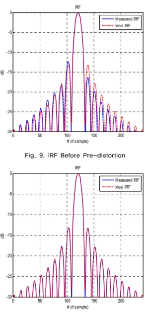
Fig. 9 shows the IRF curve comparing the ideal one to
the measured one. The measured one before predistortion has higher sidelobe than the ideal one. After the pre-distortion compensation, it is shown in Fig. 10 that the measured IRF becomes almost the same as the ideal one.
0 50 100 150 200
-30 -25 -20 -15 -10 -5 0
IRF
# of sample)
dB
Measured IRF Ideal IRF
Fig. 9. IRF Before Pre-distortion
0 50 100 150 200
-30 -25 -20 -15 -10 -5
0 IRF
# of sample)
dB
Measured IRF Ideal IRF
Fig. 10. IRF After Pre-distortion
IV. Conclusions
The wideband digital chirp signal generator is implemented with the memory-map based structure as well as I/Q modulator, and largely consists of the digital module to generate the digital chirp signal and the RF module to perform the quadrature modulation.
Furthermore, the test bench to validate the signal generator function is also developed. After various tests, it is found that the key requirements are within the
requirements. Also the amplitude and phase errors of the chirp signal generator before pre-distortion and after pre-distortion are measured. Especially, before the pre-distortion, the random phase distortion errors not meeting the distortion requirements were reduced to be well within in the requirements after pre-distortion. All results obtained will be utilized for developing the flight model of the memory map based wideband chirp signal generator for a spaceborne SAR satellite.
References
[1] Ian G. Cumming, “Digital processing of pynthetic aperture radar data”, Artech House, 2005.
[2] M. Y. Chua and V. C. Koo, "FPGA-based chirp generator for high resolution UAV SAR", PIER 99, pp. 71-88, 2009.
[3] S. Y. Kim, N. H. Myung, "Wideband linear frequency modulated waveform compensation using system predistortion and phase coefficients extraction method", IEEE Microw. Wireless Compon. Lett., vol 17, pp 808-810, Nov. 2007.
저자
김 중 표(Joong Pyo Kim) 정회원
․2000년 2월 : 경북대학교 전자공학과 박사졸업
․2000년 3월∼현재 : 한국항공우주연구 원 위성본체실 위성전자팀
<관심분야> : 초고주파회로, 안테나, 위성 통신시스템 설계, 원격측정명령계
유 상 범(Sang Burm Ryu) 정회원
․1996년 2월 : 한밭대학교 전자공학과 학사졸업
․2001년 2월 : 충북대학교 전자공학과 석사졸업
․2010년 8월 : 충북대학교 전자공학과 박사졸업
․2011년 1월∼현재 : 한국항공우주연구원 위성본체실 위성전 자팀
<관심분야> : 지구관측 위성, 마이크로파 원격 탐사, 인공위 성, 디지털 통신 원격측정명령계
임 원 규(Won Gyu Lim) 정회원
․2002년 2월 : 경북대학교 전자공학과 학사졸업
․2004년 8월 : 한국과학기술원 전기전 자공학과 석사졸업
․2008년 8월 : 한국과학기술원 전기전 자공학과 박사졸업
․2008년 9월∼2009년 9월 : 한국과학기술원 정보연구소 근무
․2008년 10월∼현재 : 한국항공우주연구원 위성본체실 위성 전자팀
<관심분야> : 인공위성 원격측정명령계, RF 통신 시스템, RFID 리더 통신 시스템, 전자파 진단 장치 시스템, EMI/EMC, 이동 통신 안테나
이 상 곤(Sang Kon Lee) 정회원
․1987년 2월 : 경북대학교 전자공학과 학사졸업
․1989년 2월 : 경북대학교 전자공학과 석사졸업
․1989년 1월∼1996년 1월 : LG정밀(주) 선임연구원
․2008년 2월 : 충남대학교 전자공학과 박사졸업
․1996년 2월∼현재 : 한국항공우주연구원 위성본체실 위성전 자팀장
<관심분야> : 인공위성 전력계 및 원격측정명령계