1
PROTOTYPE ALGORITHM OF RADIOMETRIC CALIBRATION FOR IR CHANNELS ON GOES-12
Ki-Ho Chang, Tae-Hyung Oh and Myung-Hwan Ahn
Remote Sensing Research Lab., Meteorological Research Institute, KMA Seoul 156-720, [email protected]
ABSTRACT:
The prototype of the radiometric calibration algorithm, including the correction of scan mirror's angle, has been developed for the stationary meteorological sensor, firstly in Korea. We use this system on GOES-12 to evaluate two coefficients, slope and intercept. The evaluated coefficients show good agreement with the NESDIS's results for the five-case data. The calculated coefficients have been applied to the conversion from the measured counts to the radiance and the converting methods according to the scanning are investigated to enhance the radiometric accuracy.
KEY WORDS: On-board calibration; Infrared; Radiometric correction coefficients; Space look; Black body 1. INTRODUCTION
COMS (Communication, Ocean and Meteorological Satellite), the first Korean geostationary satellite that will be launched in 2008, includes the meteorological imager.
The IR sensors of the COMS’ imager need the radiometric calibration algorithm converting the instrumental counts value into the radiance. From this converted radiance, the meterological products such as sea surface temperature would be provided.
The first step of radiometric calibration algorithm is to evaluate the calibration coefficients (slope and intercept), based on the linearity between the counts and radiance.
The two calibration coefficients are slightly differently obtained: the slopes are induced for the black body process while the intercepts are updated more often than slopes for the scanning process. Also, the IR calibration equation, after GOES-8, has accounted for the variation of the instrument's scan-mirror emissivity with scan position (Weinreb et al., 1997).
In this paper, the prototype algorithm of radiometric calibration developed for the IR sensors is validated by the IR data of the GOES-12, operated from April 1 2003, has been explained. The calculated calibration coefficients, slopes and intercepts, give a good agreement with those of NESDIS (National Environmental Satellite, Data, and Information Service).
2. BRIEF DESCRIPTION OF GOES-12
The table 1 shows the spectral and spatial characteristics of the GOES-12 imager. GOES-12 is a geostationary satellite, having both the imager and sounder, located at 75 W (Space Systems-Loral, 1994).
The GOES-12 imager uses MgF2 instead of SiO (GOES-8 and 9 used it) as a coating of scan mirror to reduce its absorption and the systematic dependency of the radiometric calibration on scan-mirror angle and temperature.
3. CALIBRATION FOR VARIATION IN SCAN- MIRROR EMISSIVITY
Relation between the radiance R and the output X of the instrument is
, (1)
where q, m, and b are the coefficients. The value of q was known a priori, having been determined from measurements made by ITT before launch.
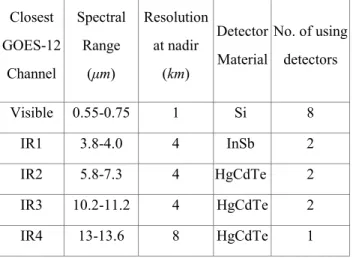
Table 1. Spectral and spatial characteristics of GOES-12 imager.
Closest GOES-12
Channel
Spectral Range
(µm)
Resolution at nadir
(km)
Detector Material
No. of using detectors
Visible 0.55-0.75 1 Si 8
IR1 3.8-4.0 4 InSb 2
IR2 5.8-7.3 4 HgCdTe 2
IR3 10.2-11.2 4 HgCdTe 2 IR4 13-13.6 8 HgCdTe 1
The coefficients m and b, termed the slope and the intercept respectively, are obtained during the in-orbit operation: at each blackbody look, m is determined by (Weinreb et al., 1997)
2
, (2)
where
, (3)
ε(45) and ε(sp) are scan mirror's emissivity at the black body and space look position, respectively. Here, and are the radiance of the blackbody and the scan mirror, calculated from the corresponding temperature respectively. It is noted that the mirror's angle at space look position is ± 10.4。 from nadir, which depends on the operation against solar intrusion.
Fig. 1. Schematic diagram of the GOES radiometric calibration including the scan-mirror angle dependence correction.
The radiance R may be calculated from the spectral response function Φ(ν) and , where ν is the wave number and monochromatic radiance, as follows:
. (4)
At each space look, the intercept is determined from
, (5)
where the prime means the count updated from the most recent space look data, differently in Eq. (2), and is the mirror radiance at the time of the space look. These
procedures of radiometric calibration are briefly described in Fig. 1.
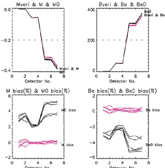
Fig. 2. The calculated calibration coefficients ((a) slopes and (b) intercepts) and the difference (bias) between the NESDIS' and our (c) slopes and (d) intercepts for 5 cases.
4. RESUTLS AND DISCUSSION
The prototype algorithm including the scan mirror emissivity dependent on the scan mirror angle has been developed for the IR sensors of stationary satellite, firstly in Korea. Applying this algorithm to the IR data of GOES-12, the effect of scan mirror emissivity to the conversion of counts to the physical radiance has been investigated.
Figure 2 shows that the calibration coefficients, M and Be, calculated by considering the scan mirror angle dependence, give better agreement with the NESDIS' results than the scan-angle independent coefficients M0 and Be0. Here, M (M0) and Be (Be0) are slope and intercept respectively, and "veri" denotes the NESDIS' results and "0" the calculated values by the procedure that the scan mirror angle dependency is not considered.
The image stripes are also improved by incorporating the scan mirror emissivity. Figure 3 shows the improved space view and the variance of the converted radiance along the N/S scan line. This improvement suggests that the modification by the scan mirror emissivity inducing the radiometric correction according to the E/W scan line is the reasonable correction.
In conclusion, the developed prototype algorithm of the radiometric calibration gives the good calibration coefficients and the radiance. Incorporating the scan mirror emissivity, the coefficients show good agreements with those of NESDIS’s, and the stripes of radiance is improved.
3 Fig. 3. The (a) unincorporated and (b) incorporated
GOES-12 radiance by the scan mirror emissivity and mean radiance for the space view component (400 sampling) from 14:45 7 December 2004. In (c), the x-axis denotes the vertical pixel of the upper images, and the largely and slightly fluctuated line denote the scan-angle independent and dependent mean radiance, respectively.
Acknowledgements
This research was performed for "Development of Meterological Data Processing System of Communication, Ocean and Meteorological Satellite".
5. REFERENCES
Weinreb, M., Jamieson, M, Fulton N., Chen, Y., Johnson, J.X., Bremer, J. B., Smith, C., and Baucom J., 1997: Operational calibration of Geostationary Operational Environmental Satellite-8 and -9 imagers and sounders, App. Optics., 36, 6895- 6904.
Space Systems-Loral, Palo Alto, Calif., 1994: "GOES I-M Data Book", NASA/GSFC Contract Rep. DRL 10108, contract NAS5-29500.
(a) (b)
0 5
-5