PRELIMINARY RESULTS OF COMS DATA CALIBRATIONS
Kyoung-Wook Jin, Seok-Bae Seo, Koon-Ho Yang
Korea Aerospace Research Institute, Daejeon, KOREA, [email protected]
ABSTRACT: COMS satellite was successfully launched on June 27, 2010. After successful completion of LEOP tests, COMS satellite is under IOT phase at its designated geostationary orbit (128.2E). The COMS has been showing pretty good shape on functionalities of all of its sub-systems. First raw images from MI sensor and from GOCI sensor showed very good performances, reflecting the excellent condition of the spacecraft and sensors. To provide valuable data to science communities, calibration processes during the IOT period is very important. Main activities for the COMS data calibrations are divided into two phases. First one is proper calibrations of the radiometric properties of MI and GOCI sensors, which are conducted heavily during the payload IOT period. Radiometric calibration is carried out according to the phase of an out-gassing activity. In case of MI sensor, only visible channel is available by the completion of the out-gassing. Therefore, the radiometric correction is performed for the visible channel first and then that of the infrared channels is followed. These radiometric calibrations for the visible and infrared channels, which ensure the quality of Level 1A data sets, are critical for a next step of calibration process. Second one is a geometric calibration called INR, which provides accurate latitude/longitude positions on the Earth surface based on the measured data from space.
COMS IDACS, which manages both radiometric and geometric calibration systems, is under rigorous testing from the real-time COMS satellite data. The preliminary calibration results of COMS data are very encouraging for various scientific and social applications.
KEY WORDS: COMS, MI, GOCI, Calibration, INR
1.
INTRODUCTION
After the long development period of COMS (Communication, Ocean and Meteorological Satellite) (started from Sept, 2003), the satellite was successfully launched at 21:41 UTC on June, 26, 2010 (6:41am, June 27, 2010 in Korea). LEOP (Launch and Early Orbit Phase, ~ 1 week) and BUS IOT were also successfully completed and the COMS operation (situated on 128.2E now) was switched over from Toulouse, France to KARI at Daejeon, Korea. Payload IOT has been heavily performed by about two months after the launch. The communication payload (Ka-band) test was mainly performed at ETRI (Electronics and Telecommunications Research Institute) and the IOT activities for MI (Meteorological Imager) and GOCI (Geostationary Ocean Color Imager) has been conducted at KARI (Korea Aerospace Research Institute) SOC (Satellite Operations Center).
The primary purpose of the IOT is the comprehensive tests of spacecraft and sensors to provide the high quality scientific data ready to be used by science communities.
Therefore, functional and performance evaluation of MI and GOCI products are crucial during the IOT. Data calibration process of the instruments were divided into two parts; radiometric and geometric calibrations. The major activities of radiometric calibrations in the early IOT phase are main focus of this paper.
2.
METHOD
2.1Radiometric Calibration
Since before the out-gassing (the release of a gas that was trapped in the spacecraft),visible channels are available, radiometric properties of the visible bands of MI and GOCI were checked and assessed first.
SNR values, the primary indicator of the quality of visible channel’s detectors were well above the specification. To monitor the degradation of the visible bands of an instrument, two methods are used. In case of GOCI, direct method using an on-board calibration target (solar diffuser) to check the absolute calibration accuracy of the sensor is used. On the other hand, MI uses an in- direct method based on the vicarious calibration target (moon). Thus, the tests of solar diffuser for GOCI and moon image acquisition for MI are important activities for the visible channel calibration. To supplement Moon image processing (1~2 times per month) for MI, additional task called “albedo monitoring” are performed everyday to monitor the degradation of the sensor qualitatively. Primary checks related with visible channel radiometry are dark noise measurement, SNR (Signal-to- Noise Ratio), pixel-to-pixel non uniformity, MTF (Modulation Transfer Function), etc.
After the out-gassing (~45days from the launch), the passive radiative cooler was opened and the infrared channels of MI has been available with full functionality.
Consequently, the radiometric calibration processes has
been started for both visible and infrared bands from this
point. The NEDT (Noise Equivalent Delta Temperature)
values for Infrared channels of MI also showed significantly enhanced features against the specifications.
Imaging operations for various conditions such as two independent detector sides (primary side and redundancy side and different patch temperatures (patch mid and low) were also monitored.
For MI, instrument’s functional checks such as Scan mirror function, black-body calibration, patch temperature set point, space look side, telemetry check and electrical calibration were conducted. As a credibility check, telemetries from two independent systems (EGSE (Electrical Ground Support Equipment) and IMPS (Image Pre-processing Subsystem) were also inter- compared.
In case of GOCI instrument, telemetry verification, detector thermal control verification, GOCI thermal behavior at day/night, pointing sequence verification, slop overlap and IMC management, detection chain performance verification (e.g. darkness, noise, calibration) were carried out.
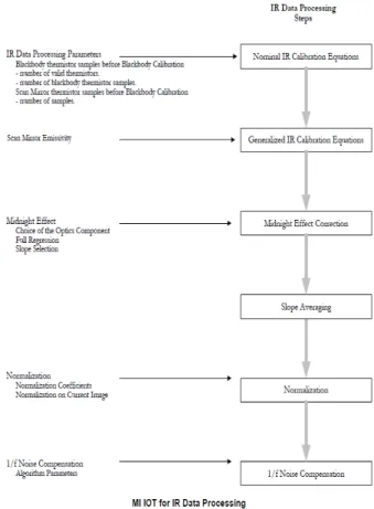
The software module for calibrations of MI and GOCI data is called IMPS. The performance of the IMPS system were intensively checked and evaluated during the payload IOT period (~ 2months from the launch). The major focuses were the proper functionality of IMPS system on the various observation conditions. The Level 1A product verification, which consist of the coding of radiance regarding the proper setting of GAIN/OFFSET values, slope and intercept verification, mean space look from the system were also performed. Brief description of the MI VIS and IR data processing is shown in Figs 1 and 2. Compared to VIS data processing, that of IR is much more complicated mainly due to the diurnally varying thermal effects on the IR detectors.
Fig 1. Diagram of MI IOT VIS data processing
Fig 2. Diagram of MI IOT IR data processing
1.2 Geometric Calibration (INR)
In principle, a geometric calibration or INR (Image Navigation and Registration) is conducted from the Level 1A product, which completed the radiometric calibration process. However, during the early IOT phase, geometric calibration activities can be conducted with the incomplete data, which have a baseline radiometric quality. Thus, initial activities of INR were concentrated on the functional check of INR software module. Those are composed of preliminary operational checks, landmarks matching activation and satellite longitude estimation activation. One of the by-products of INRSM functional tests is identification of anomalies in the Level 1A product.
For the effective tests of geometric calibration, KARI Ground Segment established an INR off-line platform, which is almost identical system with a real-time INRSM (Image Navigation & Registration Software Module) operational platform. This offline system can be used for various tests without disturbing the real-time platform.
Preliminary results indicate that number of valid
landmarks is quite satisfactory. Throughout entire IOT
period, intensive tuning process of major INR parameters
will be conducted step-by-step.
3.
RESULTS
Fig 3. First MI VIS Image (July 12, 02:15UTC)
Fig 4. First MI IR Images (Aug 11, 10:15 UTC), a) SWIR, b) WV, c) WIN1, d) WIN2
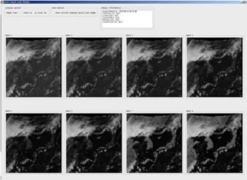
Fig 5. First GOCI Images (all eight bands) from IMPS quick look display (July 13, 06:15 UTC)
Figures 3-5 shown above are the symbolic COMS images generated first for each band. Even with very basic processing of radiometric calibrations, the preliminary products of COMS MI and GOCI show excellent performances. In case of MI Level 1A data,
shapes of the images are elliptical due to the oversampling characteristic of the instrument (1.7times more sampling of East/West directions compared to that of North/South).
Fig 6 shows the albedo monitor images for MI visible stability and degradation monitoring. The albedo monitor data are taken every morning (~ 6am in local time).
Moon images (Fig 7) are also acquired when the Moon is located within the FD image. Due to the orbital characteristic of Moon, Sun and Earth, this nominal Moon Images used for the ROLO (RObotic Lunar Observatory) model are available once or twice per month. As a result, several special missions for Moon imaging (during near full moon phase) are planned during the IOT period.
Fig 6. Albedo Monitor Image of the 14
thof July, 2010 (Courtesy of Young-Jun Chang of KARI)
Fig 7. Moon Image taken on July 16th 20:25 UTC (Courtesy of Young-Jun Chang of KARI)
The level 1B images shown in Figs 8 & 9 can be interpreted as images, which show re-sampling (re- gridding) effect mainly due to the incomplete INRSM processing. However, the products from the operational IMPS system in the very early period of IOT show very reasonable performances.
a) b)
c) d)
Fig 8. MI Level1B FD image (July 7, 2010, 02:45:24 UTC, Courtesy of Philippe Meyer of Astrium)
Fig 9. GOCI Level1B Image from IMPS quick look display (Aug 21, 2010,04:16:08 UTC)
4.
CONCLUSION
A brief summary of the radiometric and geometric calibration activities during the IOT was described.
Intensive calibration processes for the IMPS system along with the rigorous monitoring of payloads of COMS enable the high quality of scientific data for the various end-users. Preliminary data from the initial calibration process for the COMS instruments reveal excellent performances, reflecting very promising for the important science and research applications.
REFERENCES
Astrium,2010, GOCI Performances IOT Plan, 46pp
Astrium, 2010, In-Orbit Test Plan for MI, 95pp.Astrium, 2010, INR IOT Plan, 57pp
ACKNOWLEDGEMENTS