방 명 석
충주대학교 안전공학과 (2011. 3. 19. 접수 / 2011. 6. 8. 채택)Seismic Safety Assessment of Long Period Structures Base on Elastic/Inelastic Response Characteristics
Myung-Seok Bang
Department of Safety Engineering, Chungju National University (Received March 19, 2011 / Accepted June 8, 2011)
Abstract : The earthquake characteristic assessment of social overhead facilities would be an important examination issue for seismic capacity enhancement. This study is intended to reasonably evaluate the structural behavior of long- period frame structures considering near-fault and far-fault earthquake characteristics. Elastic/inelastic time history analyses were performd by selecting the objective structure which can precisely reflect the effect of input ground motion. Based on the result of numerical analysis, we have investigated response aspects of shear force, moment, acceleration and displacement according to earthquake characteristics. Moreover, in order to understand the inelastic behavior of the objective structure, we have analyzed and compared collapse modes by considering the occurrence process of plastic hinges. The outcome of this research is expected to provide the basic information for the seismic safety assessment of long-period frame structures.
초 록 : 지진별 특성이 사회간접시설에 미치는 영향을 평가하는 것은 내진성능의 향상을 위해 중요한 검토사항이
다. 이 연구에서는 근거리 및 원거리 지진의 특성을 고려하여 장주기 골조구조물의 구조거동을 합리적으로 평가 하는 방법을 비교분석하였다. 이를 위해서 입력지진동의 영향을 명확하게 반영할 수 있는 대상구조물을 선정하여 탄성 및 비탄성 시간이력해석을 수행하였다. 수치해석결과를 바탕으로 지진특성에 따른 전단력, 모멘트, 가속도 및 변위응답의 분포양상을 검토하고 차이점을 분석하였다. 또한 대상구조물의 비탄성 거동을 파악하기 위해서 소 성힌지의 발생순서를 모사운용하여 붕괴발생모드를 해석하였다. 이 연구결과는 장주기 골조구조물의 내진안전성 평가를 위한 효율적인 방법을 제시하고 근거리 지진의 안전성에 미치는 영향을 분석하였다.
Key Words : near fault earthquake, long period, frame structures, elastic/inelastic, time series, plastic hinge
1. Introduction *
Near-fault earthquakes(NFE) occur around the area where there exist active fault zones, and seismic waves which near-fault earthquakes generate cause the disa- strous results. This is why far-fault earthquakes(FFE) on which past seismic designs were based have di- fferent characteristics from those of near-fault earth- quakes. With regard to fault actions, the most distinc- tive characteristic of near-fault earthquake is that the wave velocity with long periods in the beginning
†
To whom correspondence should be addressed.
[email protected]
stage of earthquake is high and ground is permanently displaced. Compared with normal far-fault earthquakes that has the same PGA (Peak Ground Acceleration), the energy of near-fault earthquakes is huge because their velocity and displacement are very large
1)
. The studies on near-fault earthquakes started in the late 1950s, but at that time their importance was not known2)
. Since the Northridge and Kobe earthquakes, however, it has been realized that near-fault earth- quakes are not especial phenomena, and many studies have been published all over the world3,4)
. As for recent examples that evaluate the effect of near-fault earthquakes on facilities, there are few examples otherTable 1. Characteristics of selected input earthquake motions
Site Station No.
Drup* (km)
PGA (gal) PGV
(cm/s)** PGV/PGA
EW NS EW NS EW NS
Far-Fault Earthquakes
ILA002 109.11 47 71 10 11 0.21 0.15 ILA035 104.77 69 51 11 10 0.16 0.20 Near-Fault
Earthquakes
TCU052 1.84 349 439 183 221 0.53 0.50 TCU068 3.01 495 358 280 292 0.57 0.81
* Distance from Rupture, ** PGV: Peak Ground Velocity
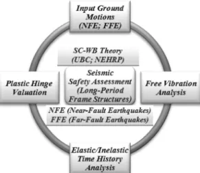
Fig. 1. Flow chart on seismic-safety evaluation of long-period frame structures.
than nuclear power plant
5)
. In this study, the records of the Chi-Chi earthquake which Guo-Quan Wang corrected and distributed have been selected in order to consider earthquake characteristics6)
. Table 1 shows the locations of the measurement points of the Chi- Chi earthquake, the distance from the rupture and its characteristics, together with the PGA from the diffe- rent directions. The effect of near-fault earthquakes on high-rise frame structures with long periods would be analyzed and compared to the effects of far-fault earthquakes based on the seismic response results by elastic/inelastic time history analyses. In addition, by investigating the formation process of plastic hinges, the inelastic response characteristics of selected earth- quakes would be examined for the seismic safety enhancement of long-period frame structures. Fig. 1 illustrates the flowchart on seismic safety assessment of long-period frame structures which are implemen- ted in this study.2. Elastic/Inelastic Response Evaluation of Long-Period Frame Structures 2.1. Profile of the Objective Structure and
Assumption Items
The inelastic behavior and damage of long-period frame structures are influenced by several factors, such as the stiffness of members, the number of occurrence of earthquakes, the frequency of ground motions, and the duration of strong base motion. Like the UBC or NEHRP, most of the seismic design standards recom- mend that structures have strong columns and weak beams (SC-WB), so that the structure should be able to disperse the incoming earthquake’s motion well and induce ductile behavior.
In SC-WB structures, it is known that the dis- placement between adjacent floors is small, and the inelastic distortion appears all over the structure
7,8)
. Therefore, a 15-story, long-period frame structures was chosen as the objective structure of this study in Fig. 2. Then, based on the SC-WB theory, the elastic/inelastic behavior has been analyzed, according to the characteristics of the input earthquake motion. At that time, three assumptions for the long-period frame structure examined in this study are as follows. First,
Fig. 2. Analytical modeling of the selected objective structure.
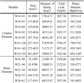
we assume that the structure is a rectangular-shaped, plane one with beams and columns, that the neutral axis of beams and columns is straight, and that their cross section does not change. In addition, it is assumed that the structure has been built based on SC-WB theory. The second assumption is concerned with the structural factor: the inelastic distortion by bending is focused on both ends of the beams, and it appears by plastic hinges. We also assume that the joints of beams and columns have bilinear behavior and beams and columns have shear distortion. The third assumption is about loads: the external load (including self-weight) applied to the members is a uniform load, and the ground moves only horizon- tally. For all mass in the dynamic analysis, lumped mass is used. Table 2 summarizes the characteristics of sections and members of the objective structure.
Fig. 3 shows the yield criterion to reproduce the inelastic behavior of the structure. In the analytical modeling, we assume that the dead load of the struc- ture on every floor is 40 kN/m, yield stress (f
y
) is 2531 kPa, and strain hardening value 0.02.2.2. Elastic/Inelastic Time History Analysis
The natural periods have been obtained by perfor- ming eigenvalue analysis of the objective structure.In order to verify the accuracy of this analysis, SAP 200N has been used, and then the results have been compared to those in this study. The natural periods of each mode are in agreement with those calculated to the third decimal point. It is evident that these values are accurate
9)
. Although up to 10th mode is shown in the Table 3, only the first five modes wereFig. 3. Yield standards applied to the objective structure.
Table 2. Section and member properties of the objective structure
Member Area, A(cm2)
Moment of Inertia, I(cm4)
Yield Load, Py(kN)
Plastic Moment, Mp(kN-m)
Column Elements
W14×43 81.2902 17814.71 2057.50 259.9113 W14×61 115.4836 26638.81 2922.95 382.2168 W14×68 129.0320 30093.53 3265.87 427.1724 W14×82 155.4836 36711.61 3935.37 511.2826 W14×99 187.7416 46201.69 4751.84 650.2671 W14×120 227.7415 57439.94 5764.25 790.5741 W14×145 275.4833 71175.57 6972.62 959.7403 W14×159 301.2897 79083.97 7625.80 1052.1407
Beam Elements
W16×40 76.1289 21560.79 1926.86 268.3925 W21×44 83.8708 35088.31 2122.81 338.4771 W21×50 94.8385 40957.17 2400.41 391.8663 W24×55 104.5159 56191.24 2645.35 475.1232 W24×62 117.4191 64515.87 2971.94 541.6055
used in this actual study. The effective modal mass summed to the fifth mode is 95.4%, which means it has enough accuracy to perform the analysis. In the numerical analysis to determine the response to the input earthquake motion, a constant average accelera- tion method has been selected. For the damping of the objective structure, Rayleigh damping has been used as follows
10)
.[C] = a
0[M] + a
1[K] (1)
where, [C] = damping matrix; [M] = mass matrix;
[K] = stiffness matrix; a
0, a
1= constants
Table 3. Natural periods of each mode of the objective structure
Mode
Natural Period (sec) Modal Participation
Factor
Mass Participation
Factor this Study SAP2000N
1 2.183 2.183 -17.647 0.733
2 0.810 0.810 -7.473 0.131
3 0.484 0.484 -4.473 0.047
4 0.334 0.334 3.330 0.026
5 0.250 0.250 -2.725 0.017
6 0.198 0.198 -2.055 0.010
7 0.160 0.160 1.803 0.008
8 0.148 0.148 0.000 0.000
9 0.137 0.137 -0.812 0.002
10 0.136 0.136 1.363 0.004
If the same damping ratio is given to adjacent two modes, a
0
and a1
can be obtained by Eq. (2).j i
j i 0
a 2
ω + ω
ω ξ ω
=
;
i j1
a 2
ω + ξ ω
= (2)
where, ω
i
and ωj
are the angular frequencies of i and j mode, respectively.We assume that the damping ratio is 5% to get a
0
and a
1
from two periods of the first mode and the second mode. The Rayleigh modal damping matrix is obtained using Eq. (1) with values, a0
= 0.2099 and a1
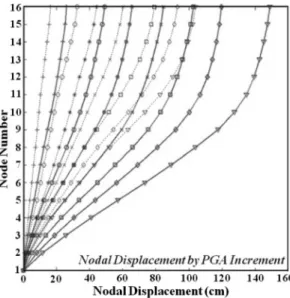
= 0.0094. PGA according to each input earthquake motion increases from 0.1 g to 0.7 g with 0.1 g increments. Fig. 4 shows fourteen curved lines(7 solid & 7 dotted lines) of the maximum displace- ment on each story as PGA increases from 0.1 g to 0.7 g by 0.1 g increment. Solid lines represent the lateral joint displacement distribution of near-fault earthquakes, while dotted lines represent those of far- fault earthquakes. Fig. 4 shows that displacement in- crease rates of near-fault earthquakes are consider- ably larger than those of far-fault earthquakes. The lateral joint displacement of near-fault earthquake with PGA = 0.5 g exceeds that of far-fault earthquakes with PGA = 0.7 g.Fig. 4. Mean displacement responses with 0.1~0.7 g from left to right(solid lines : NFE PGA, dotted lines :FFE PGA)
Fig. 5 and Fig. 6 show the maximum inter-story drift on each floor with PGA = 0.1 g and 0.5 g. For a PGA of 0.1 g, an elastic behavior without plastic hinges occurs, and for a PGA of 0.5 g, an inelastic behavior with plastic hinges occurs for every input earthquake motion. In addition, the solid lines indi- cate near-fault earthquakes, and dotted lines far-fault earthquakes. Fig. 5 indicates that in an elastic state, the inter-story displacement of near-fault earthquakes on every floor is larger than that of far-fault earth- quakes. It can be also seen that the maximum inter- story displacement occurs in the middle story of the structure. However, the inter-story drift distribution shown as in Fig. 6 is very different. Below the 10th floor, the effects of near-fault earthquakes are greater than that of far-fault earthquakes, but above the 10th floor, it is vice versa. In addition, the location of the maximum inter-story drift moves to lower stories.
This result indicates that the response pattern to an input earthquake motion is very different according to the elastic/inelastic behavior of structure. If the structure has inelastic behavior and is affected by a near-fault earthquake, the inter-story drift occurs in- tensively in the lower stories, rather than in higher stories. In an elastic state, the effects of near-fault earthquakes are great on every floor. But in an inelastic state, the effects of far-fault earthquakes are
Fig. 5. Inter-story Drift Response with PGA = 0.1 g.
Fig. 6. Inter-story Drift Response with PGA = 0.5 g.
larger than those of near-fault earthquakes. This is because when pulses start, plastic hinges occurs inten- sively in the lower stories, while it does not affect the higher stories.
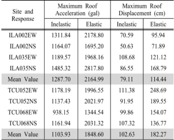
The Acceleration and displacement responses of roof story are compared by elastic and inelastic analysis when PGA = 0.5 g. Table 4 summerizes the maximum acceleration and displacement of earthquake charac- teristics by elastic and inelastic analysis. The mean acceleration and displacement responses of inelastic behavior are smaller than that of elastic behavior. In addition, the mean acceleration response of far-fault earthquakes is larger than that of near-fault earthquakes.
Table 4. Mean acceleration and displacement of near- and far-fault earthquakes by elastic/inelastic analysis Site and
Response
Maximum Roof
Acceleration (gal) Maximum Roof Displacement (cm) Inelastic Elastic Inelastic Elastic ILA002EW 1311.84 2178.80 70.59 95.94 ILA002NS 1164.07 1695.20 50.63 71.89 ILA035EW 1189.57 1968.16 108.68 121.12
ILA035NS 1485.32 2817.80 86.55 168.79 Mean Value 1287.70 2164.99 79.11 114.44 TCU052EW 1178.19 1996.55 111.38 248.69 TCU052NS 1137.43 2021.97 91.95 189.55 TCU068EW 938.15 1344.54 99.86 154.07 TCU068NS 1161.94 2031.32 107.32 136.77 Mean Value 1103.93 1848.60 102.63 182.27
Fig. 7. Mean shear force distribution at each floor level by elastic/inelastic analysis.
Fig. 8. Mean moment distribution at each floor level by ela- stic and inelastic analysis.
However, the mean displacement response is greater when it is influenced by near-fault earthquakes. Fig.
7 and Fig. 8 show the mean shear force and moment distribution of each story according to the characteri- stics of input earthquake motion. As shown in these figures, when in the elastic state and influenced by near-fault earthquakes, the shear force and moment of the lower stories is very high compared to those of the higher stories.
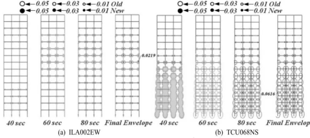
(a) ILA002EW (b) TCU068NS Fig. 9. Expansion process of plastic hinges for input earthquake motions (unit: rad).
When the structures have inelastic behavior, the differences of shear force and moment between sto- ries are reduced considerably. However, when the structures are affected by near-fault earthquakes, rather than by far-fault earthquakes, the difference is a little larger on the lower stories. Therefore, considering shear force and moment, we need to design bigger member sections to make it elastic. On the other hand, when we design it to have inelastic behavior, we can reduce the member section for a more eco- nomical situation.
2.3. Formating Process and Distribution of Plastic Hinges
Fig. 9 illustrates the fomulation process of plastic hinges under earthquake motion when PGA = 0.7 g.
The plastic hinge which is newly formed is marked with solid circles, while the ones which already exi- sted are marked with empty circles. The size of the circles is proportional to that of the plastic hinge.
The creation of the plastic hinge is related the input earthquake motion and the duration of strong base motions. In the case of far-fault earthquakes, the duration of strong base motions is between 35 and 55 seconds. On the other hand the duration of strong base motions is between 33 and 40 seconds in the case of near-fault earthquakes, It can be seen that plastic hinges occur intensely in every member of the structure whose elastic limitation is surpassed when the big pulses appear. The size of the plastic hinge of near-fault earthquakes is bigger than that of far-fault earthquakes. In far-fault earthquakes, some
of the plastic hinge occurs in the high and low sto- ries first, and then they gradually and more intensely move to the middle stories. Compared to far-fault earthquakes, the plastic hinge of near-fault earthquakes in the low stories are much bigger. Particularly in TCU068NS, the amount of plastic hinges in the low stories is much more than that of the middle stories.
Therefore, we can conclude that the inelastic behavior of a structure under the influence of near-fault earth- quakes depends on the size of the pulses and the duration.
3. Conclusions
According to the increase of PGA, the maximum displacement response on each story by near-fault earthquakes is larger than that by far-fault ones. The inter-story drift response has the maximum value in the middle story when the structure is in an elastic state. However, when the structure shows inelastic behavior, the inter-story drift has the largest value in the lower stories. In addition, the inter-story drift in an elastic state occurs greatly in every story. But when the structure has inelastic behavior, the lower stories are more influenced by near-fault earthquakes, while the higher stories are more affected by far- fault earthquakes. The shear force and moment distri- bution in each floor by elastic/inelastic time history analyses show that they get larger when the structure in an elastic state is more affected by near-fault earthquakes than by far-fault earthquakes. As the structure tends to inelastic behavior, the shear force
and moment distribution become almost the same.
From these results, it can be seen that long-period frame structures which are influenced by near-fault earthquakes will be economical if they are induced to have inelastic behavior. The formation process of plastic hinges influenced by near-fault earthquakes show big pulses, unlike those influenced by far-fault earthquakes. At this moment, the inelastic behavior of the structure is huge, and it can be seen that by the time the pulses are over, the inelastic behavior of the structure is also nearly over. In the case of far- fault earthquakes, the plastic hinge occurs first in the higher and lower stories, and then spread to the middle stories, where the biggest plastic hinge occurs.
On the other hand, in the case of near-fault earth- quakes, when the big pulses appear, the big plastic hinge occur in the lower and middle stories, and when the pulses are over, the inelastic behavior is com- plete. From the results above, it can be seen that long- period frame structures which are affected by near- fault earthquakes have different response patterns from those influenced by far-fault earthquakes. Therefore, when designing long-period structures which are lo- cated near to faults, it should be considered manda- torily in the design that the characteristics of near- fault earthquakes are reflected.
Acknowledge : The Research was supported by a
grant from the Academic Research Program of Chungju National University in 2011.References
1) M. S. Bang and S. H. Han, “A Study on Characteri- stics and Dynamic Response Spectrum of Near Fault Ground Motions”, Journal of KOSOS, Vol. 20, No. 3, pp. 143~151, 2005.
2) G. W. Housner and D. E. Hudson, “The Port Hueneme Earthquake of March 18, 1957”, Bulletin of the Seismological Society of America, Vol. 48, No. 2, pp.
163~168, 1985.
3) P. C. Jennings, “Enduring Lessons and Opportunities Lost from the San Fernando Earthquake of February 9, 1971”, Earthquake Spectra, Vol. 13, No. 1, pp. 25~
53, 1997.
4) B. A. Bolt, “Discussions of Enduring Lessons and Opportunities Lost from the San Fernando Earth- quake of February 9, 1971”, Earthquake Spectra, Vol.
13, No. 3, pp. 545~547, 1997.
5) Korea Atomic Energy Research Institute (KAERI) (2003). “Characteristics of Near-Fault Ground Mo- tions”, Report ID KAERI/TR-2453, 2003.
6) G. Q. Wang, X. Y. Zhou, Z. J. Ma and P. Z. Zhang,
“Corrected Near Fault Recordings Caused by the 1999 Chi-Chi, Taiwan Earthquake”, Bulletin of the Seismological Society of America, Vol. 9, No. 5, pp.
1358~1369, 2001.
7) UBC Code (1991-1997), “Uniform Building Code, International Conference of Building Officials (ICBO)”, Whittier, CA.
8) Building Seismic Safety Council “NEHRP recom- mended provisions for the development of seismic regulations for buildings”, FEMA-222, Washington, D C., 1994.
9) SAP2000 Analysis reference Volume I, II, Computer and Structures Inc., 1997.
10) K. Chopra, “Dynamics of Structures: Theory and Applications to Earthquake Engineering”, Prentice Hall, Inc., 1995.