GEOMETRIC CORRECTION OF GEOSTATIONARY OCEAN COLOR IMAGER (GOCI) DATA
Chan-Su Yang*1, Jung-Hwan Song1, Hee-Jeong Han1, and Gwanghyeok Ju2
1Korea Ocean Satellite Center, Korea Ocean Research & Development Institute, Ansan, P.O.Box 29, 425-600 KOREA
* [email protected] [email protected]
2Korea Aerospace Research Institute, Daejeon 305-333 Korea [email protected]
ABSTRACT: IMPS is consisted DM (Decomposition Module, 1 server), INRSM (Image Navigation and Registration Software Module, 8 servers), IMPS DB (1 server), PMM (Product Management Module with GUI, 2 servers). GOCI raw images consist of 16 “slots” that are positioned in 4 lines and 4 columns. Each slot contains 8 channels in the visible and near infer-red bands. IMPS produces Level 0, Level 1A, and Level 1B data from GOCI raw data. In the process, INRSM(Image Navigation and Registration Software Module) has a function to perform geometric correction (strictly speaking, image registration) on the input image files of Level 1A, and provide output image files containing level 1B information. In this study, we will review the geometric validation of GOCI L1B data produced at the IMPS level and estimate the INRSM performances.
Finally we will suggest a method for actual approach of GOCI level 1B.
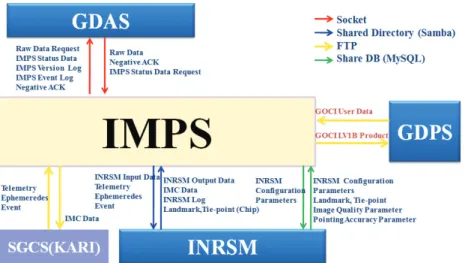
Figure 1 shows a data flow from GDAS(GOCI Data Acquisition System) to GDPS(GOCI Data Processing System). INRSM produces the parameters such as INRSM configuration, landmark, tie- point, image quality and pointing accuracy.
Fig. 1 Overview of GOCI data processing
INR operational and tuning tests are in process and will be continued until October. Preliminary results for the geometric performance are presented here with configuration parameters adjusted during tuning test. The parameters include cloud detection, landmark accuracy estimation, linear error correction, scheduler and IMC command generation parameters.
KEY WORDS: KOSC, COMS, GOCI, IMPS, INRSM
1. Concept of Geometric Correction: GOCI INRSM
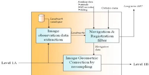
Fig. 2 Concept of geometric correction at GOCI INRSM G
INRSM input files are assumed to be radiometrically corrected. They contain level 1A image information with a header file, pixel files and an auxiliary data file. The input is made of a set of files, and is delivered for each block of data which is the same as a "slot". GOCI output data is geo- referenced and orthographic projection is used. Each INRSM output is made of a header file, one or several pixel files according to the output. A header file contains image acquisition information, output data files description, geo-referencing parameters and characteristics of INRSM processing performed for the image. A pixel file is binary format and contains 8 layers and each pixel value is coded in a 32 bits unsigned integer.
Fig. 3 Distribution of landmarks used for GOCI INRSM
Fig. 4 Level 1 B image obtained on September 1, 2010
2. Geometric Correction
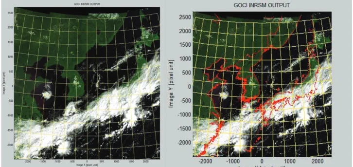
Because of IOT period at these days, level 1B data used here is the output which does not consider a registration with landmarks (Fig. 3). The data shows some errors in the comparison with coastline, and our method with 41 GCPs represents a comparatively good result as shown in Fig. 6.
Fig. 5 Visual inspection for level 1 B image, but here not considered for landmarks.
Fig. 6 An example for geometric correction using 41 GCPs. Before and after georeferencing results represent left and right images, respectively.
ACKNOWLEDGEMENTS
This work was supported by the MLTM R&D Project, “The Establishment of Korea Ocean Satellite Center” and the KORDI project (PE98492).