Combustion and Emission Characteristics of Diesel Engine by Mixing DME and Bunker Oil
Younghyun Ryu1․Tomohisa Dan†
(Received May 24, 2012; Revised July 19, 2012; Accepted August 13, 2012)
Abstract:DME (Dimethyl ether) is regarded as one of the candidates of alternative fuels for diesel engine, because of its higher cetane number suitable for a compression ignition engine. Also, DME is a simple chemical structure, colorless gas that is easily liquefied and transported. On the other hand, Bunker oil (JIS C heavy oil) has long been used as a basic fuel in marine diesel engines and is the lowest grade fuel oil. In this study, the combustion and emission characteristics were measured experimentally in the direct injection type diesel engine operated with DME and Bunker oil mixed fuel. From our experimental results, it is induced that DME and Bunker oil blended fuel would be an effective fuel which can reduces the concentration of harmful matter in exhaust gases.
Key words:Diesel engine, Alternative fuel, Exhaust gas emission, Dimethyl ether, Bunker oil
†Corresponding Author (Graduate School of Maritime Sciences, Kobe University, E-mail: [email protected], Tel: +81(78)431-6289)
1 Graduate School of Maritime Sciences, Kobe University, E-mail: [email protected], Tel: +81(78)431-6289
1. Introduction
DME (Dimethyl ether) is the smallest ether compound which is rich in hydrogen as shown by its chemical structure (CH3OCH3). In addition, it has no direct carbon bond and has a lower C-H ratio and includes an oxygen atom in the molecule.
Moreover, it can be derived from many sources, including renewable materials (biomass, waste and agricultural products) and fossil fuels (natural gas and coal). DME is a gaseous state at usual temperature and pressure. It is easily liquefied at a little pressurization, 6 bar at 20 degrees centigrade, which enable to transport and store DME within a compact volume [1]. Thus, it is regarded as one of the candidates of alternative fuels for the diesel engine, because of its higher cetane number which makes it suitable for a compression ignition engine.
Traditionally, DME has been produced in a two
step process where syngas (typically generated from steam reforming of methane) is first converted to methanol‐followed by methanol dehydration to DME. However, a new process is being commercialized to produce DME in a single step [2], namely, direct DME synthesis technology has been developed, and it will be possible to use DME as it can be produced in large quantities at a lower cost. Table 1 show the comparison of the 5year average (April 2000~March 2005) of the CIF price of DME and the other competitive fuels [1].
As seen from Table 1, it can be seen that DME is cheaper than other competitive fuels. Many investigations have been carried out on DME to determine its suitability to use as fuel in diesel engines [3]. Application of DME to diesel engines originally started as an additive to methanol fueled engines [4]. Application in large bore size engine
as large marine diesel engines, and large diesel engine generating systems have been tested with neat DME fuel [5].
Previously, the authors have shown that combustion and exhaust gas emissions were improved in diesel engines by mixing DME to fuel oils such as Marine Diesel Oil (JIS A heavy oil) and waste vegetable oil [6,7].
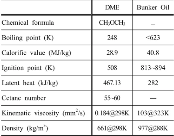
On the other hand, Bunker oil (JIS C heavy oil) has been used as the basic fuel in marine diesel engines which is the lowest grade oil in the fuel oils. The properties of test fuels are provided in Table 2. And, Table 3 show the kinematic viscosity of test fuels [8].
The exhaust gas emitted from a marine diesel engine creates air pollution problems. Thus, it is needed to reduce harmful emissions to meet the level set by legislation (ex. IMO environmental pollution regulation). Most of the marine fuel sources are fossil fuels, which have the problems of dwindling resources. So, it should be reviewed on alternative fuels for marine diesel engine application.
The object of this study is to find out whether the combustion state of Bunker oil can be improved by mixing with DME, which has been thought as one of alternative fuels. The combustion and emission characteristics were measured experimentally in direct injection type diesel engines operated with DME and Bunker oil mixed fuel.
For diesel engine application, DME has a problem of poor lubricity due to its lower viscosity (0.184 mm2/s at 25 degrees centigrade [9]) and Bunker oil has problems of smoke emission and high viscosity (103 mm2/s at 50 degrees centigrade [8]). Especially, Bunker oil need to be heated up to 100 degrees centigrade to reduce its viscosity applicable for engine use. In this experiment, Bunker oil can be used without heating in marine
diesel engine by mixing with DME.
From our experimental investigation, it is supposed that DME can improve the combustion process of Bunker oil such as the ignition delay, the heat release rate and the premixed combustion region.
Table 1: Comparison of the 5year average of the CIF price to Japan to DME with other competitive fuels [1]
[$/MMBTU]
Competitive fuel
5 year
average DME Difference % Crude oil 5.10
4.13
‐0.97 ‐19
Coal oil 6.98 ‐2.85 ‐41
Diesel oil 6.51 ‐2.38 ‐37
Bunker A 6.46 ‐2.33 ‐36
Bunker C 5.12 ‐0.99 ‐19
LPG 6.79 ‐2.66 ‐39
LNG 4.73 ‐0.60 ‐13
Table 2: Properties of test fuels
DME Bunker Oil
Chemical formula CH3OCH3 ―
Boiling point (K) 248 <623
Calorific value (MJ/kg) 28.9 40.8
Ignition point (K) 508 813~894
Latent heat (kJ/kg) 467.13 282
Cetane number 55~60 ―
Kinematic viscosity (mm2/s) 0.184@298K 103@323K Density (kg/m3) 661@298K 977@288K
Table 3: Kinematic viscosity of test fuels Temp. of fuel
(K) C100 C80D20 C60D40
308 239 39.1 13.6
323 103 34.9 11.4
343 44.8 10.1 5.9
Also, CO2, CO emissions were reduced.
Especially, HC, the smoke and the PM (Particulate Matter) emissions showed remarkable reduction in cases of mixing with DME. The detail of the experimental method and results are described in the following sections.
2. Experimental Apparatus and Method
2.1 Test Engine
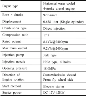
In this experiment, a small high‐speed direct injection single cylinder (bore: 92mm, stroke:
96mm) horizontal water cooled 4 stroke diesel engine was used as the test engine. It had a constant compression ratio of 17.7:1. When using Bunker oil as the engine fuel, a larger size diesel engine is preferable instead of the test engine of this study. Due to restrictions of the experimental setup, it had to be used the smaller engine. The fuel injection pump was a jerk type. It is directly cooled by water to prevent vapor lock due to evaporation of DME. The test engine specifications are shown in Table 4. No more modifications were made on the engine except the fuel pipe and fuel tank. The fuel pipe was modified to use mixed fuel comprised of DME and Bunker oil. In order to block fuel leakage, some joints were modified, and then connected up.
Figure 1 is a schematic of fuel tank used in this study. A pressure‐resistant closed vessel of stainless steel was made as a fuel tank to adjust fuel‐supply pressure. And, it was designed as the separated to clean the fuel tank inside. A supply port of nitrogen was set separately from the fuel port on the tank, and the pressure on the surface of mixed fuel was increased by using nitrogen gas of 2.3MPa. Due to the low boiling point (248K) of DME, with this pressurization, it was possible to treat DME as a liquid fuel at usual ambient temperatures. And fuels were supplied to the engine through nozzle opening pressure of 18MPa.
2.2 Experimental Method
Schematic diagram of experimental apparatus is shown in Figure 2. The experimental conditions for the combustion performance examination are as follows. The air charging pressure was maintained at 18kPa. Fuel‐supply pressure (backpressure inner fuel tank) was maintained at 2.3MPa constant. The DME and Bunker oil blend fuels were extracted from the fuel tank in the liquid phase, and the pressurized blended fuel was introduced to the fuel pumps of the engine.
Three parameters, the engine speed, the engine load and the mixing ratio of DME, are varied in this study. The engine was operated at 3 different speeds (1200, 1400, 1600rpm), the engine load was changed at 4 steps (25, 50, 75, 100% of rated output). The DME (20, 40% by weight ratio) and Bunker oil blend fuels were used as the test fuels.
For comparison, the neat Bunker oil was also tested. The injection pressure and the combustion pressure histories were measured by the averaging of 50 cycles of the piezo type pressure sensors.
Table 4: Test engine specification
Engine type Horizontal water cooled 4‐stroke diesel engine
Bore × Stroke 92×96mm
Displacement 0.638 liter (Single cylinder) Combustion type Direct injection
Compression ratio 17.7
Rated output 8.1kW@2400rpm
Maximum output 9.2kW@2400rpm Injection pump Jerk type Injection nozzle Hole type, 4 holes Opening pressure 18.0MPa
Direction of Engine rotation
Counterclockwise viewed From fly wheel side Start method Electric starter Starter power DC 12V‐1.2KW
Figure 1: Schematic of fuel tank
Figure 2: Schematic diagram of experimental apparatus
2.3 Exhaust Emissions Analysis Equipment
The exhaust emissions analysis equipment consists of analyzers for measuring soot (smoke), nitrogen oxides (NOx), carbon dioxide (CO2), carbon monoxide (CO) and hydrocarbon (HC). The smoke level in the exhaust gas was measured by optical measuring method with a smoke meter (BAZAI DSM‐10). NOx emission was measured by chemical luminescence method (HORIBA CLA‐
510SS). CO, CO2 and HC emissions were measured by the non‐distributed infrared analyzing method (HORIBA MEXA‐324J). Particulate Matter (PM) was trapped using PM filter, and then the filter was solved for 12hours with 20cm3 of dichloro‐methane to divide PM on filter into Insoluble Organic Fraction (ISF) and Soluble Organic Fraction (SOF).
After that, the filter was dried for 2 hours, and then the weight of filter measured to calculate the weight of ISF.
3. Results and Discussion
3.1 Fuel Injection Characteristics
Fuel injection pressure was measured to capture the effect of DME blending to Bunker oil. Figure 3 shows the time history of fuel injection pressure of each fuel. The injector was set to open at 18MPa for each fuel. When mixing DME, the fuel injection period extends at both loads. The calorific value of DME is about 80% lower than that of neat Bunker oil. It is considered that a larger amount
Figure 3: Time history of fuel injection schematic
Figure 4: Fuel injection period
of fuel supply is needed to maintain the same engine load. In case of mixing DME, the injection pressure before injection start got a gentle incline in comparison with neat Bunker oil, which became obvious in higher engine load case. The reason for this is as follows. DME has lower elasticity coefficient in comparison with Bunker oil, that results in an easier compression of the fuels instead of raising their pressure. From Figure 3, the fuel injection period is calculated and shown in Figure 4. The fuel injection period was defined as the fuel injection start timing (nozzle opening pressure, 18MPa) to the fuel injection end timing (80% of nozzle opening pressure, 14.4MPa). When DME content is high in the blended fuel, the injection period increases compared to neat Bunker oil.
The increase ratio of 40% DME blended case is 177% for 25% engine load, 34% for 50% load, 17% for 75% load and 11% for 100% load. It can be seen that the increase a ratio of lower engine load is much higher than that of higher engine load. It is considered that the combustion efficiency deteriorated in the lower engine load cases.
3.2 Combustion Characteristics
Combustion process of each fuel can be estimated by the pressure change in the combustion chamber. Thus, the combustion pressure was measured to obtain the combustion characteristics.
Figure 5 shows the time history of combustion pressure of each fuel. The combustion pressure rises earlier when using mixing fuel as compared to neat Bunker oil. It was also found that the maximum combustion pressure increased with mixed fuels. It was supposed that the higher cetane number of DME compared to Bunker oil resulted in the earlier fuel ignition, and also DME has a lower boiling point which results in a rapid evaporation of fuel spray.
Figure 5: Combustion pressure history
From the combustion pressure of Figure 5, the rate of heat release is calculated and shown in Figure 6. And from the rate of heat release, the premixed combustion stage period is calculated and shown in Figure 7. Heat release rate rose after the ignition delay period and reached its peak value.
Figure 6: Rate of heat release
After the peak, it declined with a change in its inclination. The end point of premixed combustion is defined as the first changed position of its inclination. Therefore, the premixed combustion period was calculated with time duration from the ignition point to the end point mentioned above.
The earlier ignition of DME mixed fuels is obvious in Figure 6. Also, it is obtained that the peak of heat release rate becomes higher in proportional to DME mixing ratio. On the other hand, from Figure 7, it can be seen that the amount of heat release during the premixed combustion stage of mixed fuel is slightly smaller than that of neat Bunker oil. It means that the diffusion combustion period occupies more duration in the total combustion period. Thus, it can be considered that the diffusion combustion region was activated by mixing DME.
Figure 7: Premix combustion period
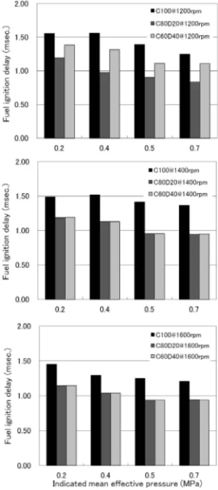
From the injection start timing and the combustion start timing, the ignition delay was calculated and shown in Figure 8 for every engine speed. It shows that the ignition delay becomes shorter when mixing with DME. Also, it was
Figure 8: Fuel ignition delay
obtained that the ignition delay becomes shorter when the DME mixing ratio was increased, except 1200rpm case. In the lower engine speed cases, it was assumed that heat loss from the combustion chamber and cylinder walls brought an increase in lower air temperature inside the combustion chamber. Thus, the rapid evaporation of DME results in decreasing the temperature of the combustible mixture, that leads to a longer ignition delay for higher DME mixing ratio fuel.
3.3 Emissions Characteristics
Exhaust emissions are measured in order to understand the combustion efficiency, of test fuels.
The results are shown in Figure 9 to Figure 14.
Figure 9 shows the comparison of NOx emission in each fuel. In the lower engine load condition
case, NOx emission of DME mixed fuels increased in comparison to the neat Bunker oil. The reason that the maximum value of heat release rate is higher than neat Bunker oil is shown in Figure 6.
And, in the case of mixed fuel, fuel injection timing became faster with effect of fuel pressurization. Thus, a higher generation of NOx emission occurred in cases of lower engine load conditions. However, in the higher engine load case conditions, NOx emission was reduced (max. about 20%) by mixing DME. The ignition delay of mixed fuels was shorter and the amount of premixed combustion was smaller than those of neat Bunker oil as shown in Figure 7 and Figure 8. So, NOx emission was reduced in cases of DME mixing.
Figure 10 and Figure 11 show the comparison of CO and HC emissions in each fuel. It turns out that CO and HC emissions decreased in proportion to the mixing ratio of DME. This trend was also reported in other investigations [3,6]. There are two reasons for the trend. One of them is that DME is a higher cetane number fuel (above 55) and is a lower boiling point (248K) fuel. These aspects
Figure 9: NOx emission
Figure 10: CO emission
enhance the atomization and ignition of the fuel.
The other reason is that the peak combustion pressure increases in proportion to the mixing ratio of DME. This aspect tells that the combustion
Figure 11: HC emission
Figure 12: CO2 emission
Figure 13: Smoke opacity
Figure 14: PM emission
inside the chamber was activated by mixing DME.
Thus, those imperfect combustion components, CO and HC, are reduced by mixing DME. The CO values tend to decrease with increasing the engine load. However, in case of Pi 0.7MPa, it has increased more than that of 0.4, 0.5MPa. This result is thought to be the worse oxidation of fuel where the amount of injected fuel exceeds the moderate fuel/air ratio.
Figure 12 shows the comparison of CO2
emission in each fuel. It turns out that CO2
emission decreased in proportion to the mixing ratio of DME. As the fuel injection period increased by mixing DME, as shown in Figure 4, the emission of CO2 was reduced to obtain the same engine load with the different fuels. The reason for the decrease may be because DME has a lower carbon content (52%wt.) than Bunker oil (84~88%wt.). Thus, the heat energy to obtain the same engine output was realized with less CO2
emission in the case of DME mixing.
Figure 13 shows the comparison of the smoke opacity in each fuel. It turns out that the smoke opacity decreased in proportion to the mixing ratio of DME. It is because DME contains an oxygen atom (34.8%wt.) and has no direct carbon bond. It is also assumed that the aromatics fractions were reduced to replace Bunker oil with DME mixing.
The weight of Particulate Matter (PM) was also measured and shown in Figure 14. Both ISF and SOF were reduced by mixing DME.
In case of the higher DME content in the blend fuel, we found that ISF decreases about 30%, SOF decreases about 70% and the total PM was reduced about 50%. This trend means there is a reduction of unburned fuel which agrees with CO and HC results.
4. Conclusions
In this study, the effect of mixing DME with
Bunker oil (JIS C heavy oil) is investigated using combustion and emission characteristics in direct injection type diesel engines. The combustion and emission characteristics were compared by changing the engine speed, the engine load and the mixing ratio of DME. From our experiments, the following results were obtained.
(1) When Bunker oil is mixed with DME, the fuel injection period becomes longer than that of neat Bunker oil. The increase in the ratio of the injection period becomes smaller with an increase in the engine load.
(2) Ignition delay tends to shorten with mixing DME, except at the lowest engine speed case. And the premixed combustion period becomes smaller in cases of DME mixing. However, the peak heat release rate increase in proportion to the DME mixing ratio.
(3) The imperfect combustion components, such as CO, HC, Smoke and PM, are reduced by mixing DME. Also, CO2 emissions can be reduced using DME blended Bunker oil.
From experimental results, it is supposed that DME can improve the combustion process of Bunker oil. It is effective to reduce the imperfect combustion components and CO2 emissions.
However, it is needed to investigate further, such as reduction of NOx emission to meet the level set by legislation such as IMO regulations.
References
[1] DME Handbook, Japan DME Forum, 2007.
[2] T. Ogawa, “Mass production technology of direct DME synthesis,” Journal of the Japan Institute of Marine Engineering, vol. 40, no. 6, pp. 49‐54, 2005 (in Japanese).
[3] C. Arcoumanis, C. Bae, R. Crookes, and E.
Kinoshita, “The potential of Dimethyl ether
(DME) as an alternative fuel for compression‐
ignition engines: A review,” Fuel, vol. 87, pp.
1014‐1030, 2008.
[4] S. Kajitani, “Engine performance and exhaust gas characteristics when operated with Dimethyl ether (DME),” Journal of the Japan Institute of Marine Engineering, vol. 40, no. 6, pp. 19‐24, 2005 (in Japanese).
[5] K. Masuda, “Development of DME large diesel engine generation system,” Journal of the Japan Institute of Marine Engineering, vol. 40, no. 6, pp. 45‐48, 2005 (in Japanese).
[6] T. Dan, M. Hashimoto, I. Asano, T. Nakamura, and A. Kunikawa, “Combustion characteristics of diesel engine with mixing of DME to fuel oils,” Proceedings of the 7th International Symposium on Marine Engineering Tokyo, 2005.
[7] T. Dan, M. Hashimoto, I. Asano, and A.
Kunikawa, “Improvement of exhaust gas emission in marine diesel engine by blending DME,” Society of Automotive Engineers Technical paper, SAE 2007‐01‐2014, pp. 1‐6, 2007.
[8] T. Dan, Y. Ryu, M. Mizukura, and I. Asano,
“Kinematic viscosity measurement of DME and bunker oil blended fuel for diesel engine application,” Proceedings of the Eighth Thermal and Fluids Engineering Conference Incheon, 2012.
[9] I. Sivebaek, and J. Jakobsen, “The viscosity of Dimethyl ether,” Tribology International, vol.
40, pp. 652‐658, 2007.