Ⅰ. 서 론
Bone-Anchored Hearing Aid (BAHA) implant는 난청 환자의 청력을 복구하는데 사용되는 골전도 보청기이다. 이 장치는 귀 후방의 측두골에 이식 된 후 골성결합으로 견고하 게 결합되어 소리의 진동을 두개골을 통해 전달하게 된다[1]. BAHA implant의 고정장치(fixture)와 지지대(abutment)
는 측두골에 이식되는 장치로 상자성체인 티타늄으로 되어 있다. 인체 내에 의료용 금속성 장치를 가지고 있는 환자가 Magnetic Resonance Imaging (MRI)를 시행하게 될 경우 에 금속과 자기장의 상호작용에 의한 발열, 회전력, 수평인 력 등에 의해 환자안전에 심각한 문제가 발생할 수 있다
[2-5]. Mark J. 등의 연구에서는 티타늄이 비록 적은 자기모
멘트(0.046 emu/g)를 가지고 있지만, MRI 장치가 강한 자
Journal of Radiological Science and Technology, 40(1), 19-25 eISSN 2384-1168 ISSN 2288-3509 http://dx.doi.org/10.17946/JRST.2017.40.1.04
<원저>
Bone-Anchored Hearing Aid Implant에 대한 1.5 T와 3.0 T에서 MRI 안전성의 생체외 평가
- In Vitro Assessment of MRI Safety at 1.5 T and 3.0 T for Bone-Anchored Hearing Aid Implant -
1)삼성서울병원 영상의학과・2)충북대학교 의용생체공학과 연규진1,2)・김현수1)・이승근1)・이태수2)
― 국문초록 ―
본 연구는 1.5 T와 3.0 T Magnetic Resonance Imaging에서 Bone-Anchored Hearing Aid (BAHA) implant의 수평인력, 회전력, 그리고 자화감수성 인공물의 크기를 표준측정 방법에 의해 측정하여 MR 안전성을 평가하였다.
BAHA implant의 고정장치와 지지대는 0.5%의 철(iron)이 포함 된 티타늄으로 만들어졌으며, 길이는 10 mm (고정 장치 4 mm, 지지대 6 mm), 최대 직경은 7.0 mm이다. 수평인력 측정장치와 자화감수성 인공물 측정장치는 각각 American Society for Testing and Materials (ASTM) F2052-06, F2119-07을 참조하여 아크릴을 이용해 제작했으며, 회전력 측정은 원형 플라스틱 용기를 이용한 측정장치를 사용하였다. 자기유도에 의한 BAHA implnat의 수평인력 은 주자장이 가장 큰 지점인 96 cm지점에서 최대 변위각을 측정하였고, 회전력은 원형용기 내부의 45°간격의 실 선 위에 놓았을 때 나타난 회전형태를 정성적 평가기준으로 측정하였다. 자화감수성 인공물은 황산구리(CuS04) 용 액이 채워진 용기의 중앙에 BAHA implant를 매달아 영상을 획득한 후 Susceptibility Artifact Measurement (SAM) software를 이용해 크기를 측정하였다. 측정결과 수평인력은 1.5 T와 3.0 T에서 변위각과 변위력은 모두 0으로 나 타났다. 회전력은 1.5 T에서는 0(no torque), 3.0 T에서는 +1(mild torque)로 나타났다. 자화감수성 인공물은 최소 13.20 mm, 최대 38.91 mm의 크기로 나타났다. 따라서 1.5 T, 3.0 T의 MR 환경에서 BAHA implant는 환자에게 안전하다.
중심 단어 : 바하 임플란트, 안전성, 자화감수성 인공물, 수평인력, 회전력
Corresponding author: Tae-Soo Lee, Department of Biomedical Engineering, Chungbuk National University, 1, Chungdae-ro, Seowon-gu, Cheongju-si, Chungcheongbuk-do, Korea (28644) / Tel: +82-43-269-6332 / E-mail: tslee@chungbuk.ac.kr Received 19 January 2017; Revised 9 March 2017; Accepted 15 March 2017
기장으로 발전하고 있으므로 MR적합성에 대한 평가는 간과 할 수 없음을 설명하였다[6]. BAHA implant와 MR 자기장 에 의한 상호작용을 평가한 이전연구에서 BAHA implant를 이식한 환자에게 Brain MRI를 1.5 Tesla (T) 또는 3.0 T에 서 시행한 결과 자기장에 의한 BAHA implant의 변위는 관 찰되지 않았고[7], 자화감수성 인공물의 크기는 시퀀스 (sequence)에 따라 15.1 mm 또는 17.4 mm로 나타났음을 보고하였다[8]. 이와 같은 이전 연구에서는 체내 실험을 통한 BAHA implant 수술 후 측두골과 implant간의 골성결합의 평가 유용성과 implant 삽입환자에 대한 MRI 검사 시 환자 의 위해 가능성 등을 임상적인 기준에 의해 평가하였다. 하 지만 의료용 implant에 대한 MR적합성은 미국재료시험협 회(American Society for Testing and Materials, ASTM) 의 표준측정 방법에 의해 평가되고 있다. 따라서 본 연구의 목적은 1.5 T와 3.0 T MRI에서 BAHA implant의 수평인 력, 회전력, 그리고 자화감수성 인공물의 크기를 표준측정 방법에 의해 측정하여 MR 안전성을 평가하고자 한다.
Ⅱ. 연구방법
1. 실험장치
본 연구에서는 BAHA implant (Flange fixture ST 4 mm/
Baha abutment, Cochlear Corporation, Lane Cove, Australia)의 구성장치 중 고정장치와 지지대를 대상으로 하였다. 음향처리기는 체외장치로서 임상에서 MRI검사 시 행 시 탈거해야 하는 MR금기 장치이므로 대상에서 제외하 였다. 고정장치와 지지대는 0.5%의 철(iron)이 포함된 티타 늄으로 만들어졌으며, 길이는 10 mm (고정장치 4 mm, 지 지대 6 mm), 최대 직경은 7.0 mm이다. MRI장치는 1.5 T MRI system (Achieva, Philips Medical System, Best,
Netherland)와 3.0 T MRI system (Achieva TX, Philips Medical System, Best, Netherland), 그리고 8 chanel head coil (SENSE head coil 3.0T/8ch, Invivo corporation,
Gaineville, USA)을 사용하였다. 수평인력 측정장치와 자화감수성 인공물 측정장치는 각각 ASTM F2052-06, F2119-07을 참조하여 아크릴을 이용해 제작했으며, 그 형 태는 Fig 1, 2와 같다[9,10]. 회전력 측정은 원형 플라스틱 용 기를 이용한 측정장치를 사용하였다. 플라스틱 용기를 이용 한 정성적 회전력 측정방법은 이전의 연구들에서도 소개되
었다[11,12]. 원형 플라스틱 용기의 밑면에는 5 mm 간격의 격
자가 표시되어 있으며, 360°를 45°간격으로 8등분하는 실 선을 표시하였다(Fig 4).
2. 실험방법
1) 자기유도 수평인력의 평가
자기장에 의한 수평인력의 평가는 변위각(deflection angle) 측정장치를 이용하였다(Fig 1). 측정장치에 고정된 나일론 실에 BAHA implant를 매단 후 MRI장치의 주자장 이 가장 큰 지점인 Z축 중심으로부터 96 cm 지점에 위치시 켰다[11]. 실에 고정된 BAHA implant가 측정장치의 각도기 에 0°가 되도록 고정하였다가 놓았을 때 자기장에 의해 이 끌린 최대각도를 3회 반복하여 측정하였다. 동일한 실험을 1.5 T와 3.0 T에서 시행한 후 아래 공식 (1)을 이용하여 변 위력()을 계산하였다(Fig. 3).
∙ tan (1)
(: implant의 질량, : 중력가속도, : 변위각)
2) 자기유도 회전력의 평가
원형 플라스틱 용기를 회전력이 가장 큰 MR장치 정중앙 Fig. 1 Test tool of deflection angle with suspended BAHA
implant by a nylon string and placed at 96 cm from the center of the bore
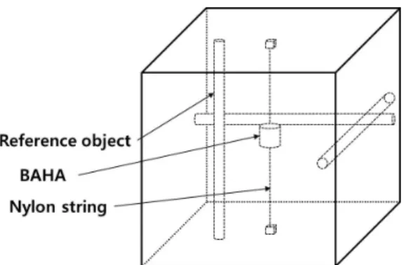
Fig. 2 Test tool of susceptibility artifact with suspended BAHA implant inside a container filled with CuS04 sulfate solution
에 위치시키고, 용기의 바닥에 그어진 45°간격의 실선 중 0°
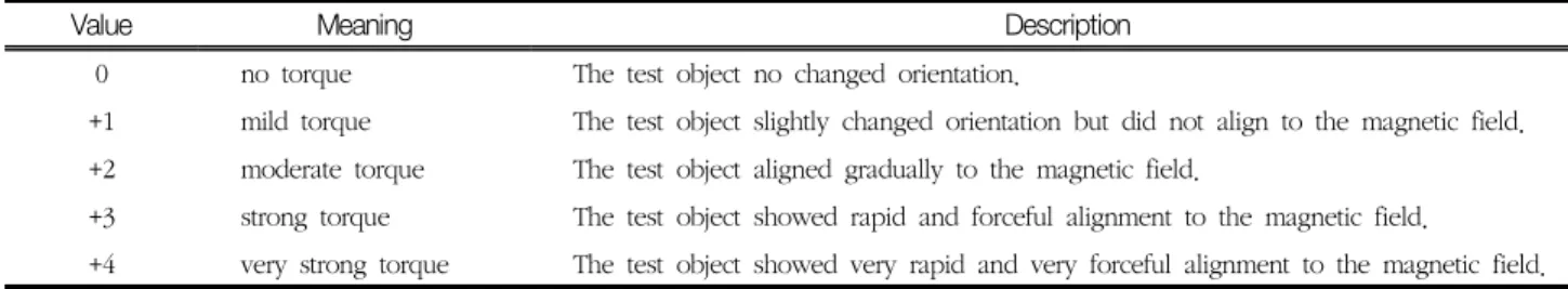
실선이 MR의 주자장과 나란하도록 위치를 조정하였다. 먼 저 BAHA implant의 장축이 0°실선에 평행하도록 올려놓은 후 자기장에 의해 회전력을 발생하게 되면 Table 1의 정성 적 평가기준[11]에 의해 측정하였다. 다음 BAHA implant의 장축을 45°실선에 평행하도록 올려놓은 후 회전력을 평가하 였다. 동일한 방법으로 45°간격의 8등분 실선에 순차적으로 이동시켜 회전력을 3회씩 평가하였으며, 1.5 T와 3.0 T에서 모두 측정하였다.
3) 자화감수성 인공물의 평가
자화감수성 인공물 측정장치에 1% 황산구리(CuSO4) 용액 을 채운 후 BAHA implant를 나일론실을 이용하여 중심부 에 고정하였다. MR영상은 T1-SE와 GRE pulse sequence 에서 획득하였다. Pulse sequence의 scan parameter는 Table 2와 같다. 주파수 부호화 방향은 BAHA implant의
장축과 평행하게 설정하였다. 획득된 SE와 GRE pulse sequence 각각의 영상에서 자화성 인공물이 가장 크게 나타 난 영상을 선택한 후 Susceptibility Artifact Measurement (SAM) software[13]를 이용하여 BAHA implant의 장축과 단축에서 각각 인공물의 크기를 측정하였다. 동일한 방법으 로 1.5 T와 3.0 T에서 영상을 획득한 후 인공물의 크기를 측 정하였다.
Ⅲ. 결 과
1. 자기유도 수평인력의 평가
BAHA implant에 대한 수평인력의 측정결과 1.5 T와 3.0 T에서 자기장에 의한 움직임이 없었다. 따라서 변위각과 변 위력은 모두 0으로 나타났다(Table 3).
Fig. 3 Equation of calculating deflection force
∙ tan.
Fig. 4 Tool of Torque with 45° interval lines in the circular plastic container
Table 1 Qualitative evaluation criteria in Torque test
Value Meaning Description
0 no torque The test object no changed orientation.
+1 mild torque The test object slightly changed orientation but did not align to the magnetic field.
+2 moderate torque The test object aligned gradually to the magnetic field.
+3 strong torque The test object showed rapid and forceful alignment to the magnetic field.
+4very strong torque The test object showed very rapid and very forceful alignment to the magnetic field.
Table 2 Scan parameter in susceptibility artifact test
Sequence TR
(ms)
TE
(ms) Matrix size Slice thickness (mm)
FOV (mm)
Bandwidth (kHz)
Flip angle (°)
T1-SE* 500 20 256×256 3 130 32 -
GRE** 296 15 256×256 3 130 32 30
*SE: Spin echo, **GRE: Gradient echo
2. 자기유도 회전력의 평가
BAHA implant에 대한 회전력의 측정결과 1.5 T에서는 0(no torque), 즉 회전력이 나타나지 않았다. 반면 3.0 T에 서는 +1(mild torque)로 천천히 방향의 변화를 일으키지만 주자장의 방향과 정렬되지는 않았다(Table 3).
3. 자화감수성 인공물의 평가
자화감수성에 의해 발생된 인공물에 대한 평가결과는 Table 4와 같이 나타났다. 자화감수성 인공물의 크기는 1.5 T의 경우 T1-SE에서 단축 13.79 mm, 장축 18.36 mm, GRE에서 단축 19.78 mm, 장축 29.61 mm로 나타났으며, 3.0 T의 경우 T1-SE에서 단축 15.43 mm, 장축 19.75 mm, GRE에서 단축 23.67 mm, 장축 34.67 mm로 나타났다. 자 화감수성 인공물의 형태는 Fig. 5와 같이 나타났다.
Ⅳ. 고 찰
BAHA implant와 자기장과의 상호작용에 대한 평가결과 변위각은 1.5 T와 3.0 T에서 모두 0으로 나타났다. ASTM 에서는 ‘implant가 45° 미만의 변위각을 나타낸다면, 자기 장으로 인해 유도된 변위력이 implant에 작용 된 중력보다 작다’라고 정의하고 있다. 즉 이와 같은 조건에서는 자기장 에 의해 유도된 힘에 의한 위험이 일상적인 지구 중력에서 의 활동으로 인해 부과 된 위험보다 작다는 것을 의미한다
[9]. 또한 회전력의 평가결과는 1.5 T와 3.0 T에서 각각 0, +1로 no torque, mild torque로 나타났다. 의료용 장치와 implant에 대한 회전력은 일상생활에서 발생되는 회전력보 다 작다면 MR환경에서 안전하다고 평가된다[14]. 이를 근거 하여 회전력에 대한 정성적 평가에서 나타난 0과 +1은 낮은 회전력을 나타내며, 이전 연구들에서 MRI환경에서 환자에 게 안전하다고 평가되었다[11,12,15]. 따라서 1.5 T와 3.0 T에 서 수평인력과 회전력의 체외 평가결과에 의해 BAHA implant를 시술한 환자는 MR환경에 노출되어도 안전하다.
회전력에 대한 정성적 평가에서 1.5 T에서는 회전력이 0 이었으나, 3.0 T에서는 +1로 나타났다. 이에 대해 환자 안 전의 측면에서 엄격하게 고려한다면 비록 낮은 회전력이더 라도 인체 내에서 발생하게 되므로 그 안전성에 대해 의구 심을 가질 수 있다. 그러나 BAHA implant의 screw형태의 결합부위는 두개골과 단단하게 결합되어 자기장에 의한 낮 은 회전력을 견뎌내는 충분한 저항력을 갖게 되어 인체에서 의 움직임을 예방할 수 있다. Fritsch 등의 연구[7]에서 사체 (cadaver)의 측두골(temporal bone)에 BAHA implant를 이식한 후 9.4 T MRI magnet에 노출시킨 결과 결합부위의 유격이 발생되지 않았다는 보고에 의해 그 안전성을 확인할 수 있다.
BAHA implant에 대한 자화감수성 인공물을 평가한 결 과 1.5 T에서는 13.20~33.42 mm로 나타났고, 3.0 T에서 Table 3 Measurement value of deflection angle and Torque at 1.5 T, 3.0 T
Main magnetic field Defection angle Torque
1.5 T 0 0
3.0 T 0 +1
Table 4 Size of susceptibility artifact at 1.5 T and 3.0 T (unit: mm) Main magnetic field T1-SE* (Long axis) T1-SE (Short axis) GRE** (Long axis) GRE (Short axis)
1.5 T 18.36 13.79 29.61 19.78
3.0 T 19.75 15.43 34.67 23.67
*SE: Spin echo, **GRE: Gradient echo
Fig. 5 Images of the susceptibility artifact for BAHA implant.
(a) T1-SE image at 1.5 T, (b) GRE image at 1.5 T, (c) T1-SE image at 3.0 T, (d) GRE image at 3.0 T
는 15.43~38.91 mm의 크기로 나타났다. 자화감수성 인공 물의 크기는 주자장(B0)에 비례하므로[16] 이번 연구결과에서 도 1.5 T에서 인공물의 크기가 3.0 T에서 보다 작게 나타난 것을 확인할 수 있었다. 자화감수성 인공물은 상자성체인 BAHA implant에 의해 주자장에 불균질이 발생하여 나타나 는데, 낮은 주자장에서는 implant를 둘러싼 자기장이 감소 되어 국소자장의 왜곡이 줄어들게 되므로 결과적으로 낮은 주자장에서 인공물의 크기가 감소하게 된다[17]. 또한 자화감 수성 인공물은 1.5 T와 3.0 T 모두에서 SE일 때 보다 GRE 에서 인공물의 크기가 더 크게 나타났다(Table 4). SE에서 는 180° RF pulse에 의해 탈위상(de-phase)된 스핀을 재위 상화(refocusing)시키게 되어 주자장에 의한 왜곡을 최소화 할 수 있기 때문이다[17].
Arndt 등의 연구에서는 3.0 T MRI영상에서 자화감수성 인공물의 크기가 T1 axial영상에서 15.1 mm, T1 coronal영 상에서 17.4 mm로 나타났음을 보고하였다[8]. 그러나 이전 연구에서의 인공물의 크기는 임상영상에서 BAHA implant 와 두개골의 결합부위에서의 신호감쇄영역의 길이, 즉 두개 골이 묘사되지 않는 영역(black hole)의 직선거리를 측정한 크기이다. 이와 같은 측정방법은 자화감수성 인공물의 크기 를 직접 측정하는 표준방법과는 차이가 있으며, 표준 측정 방법을 이용한 이번 연구에서는 3.0 T에서 인공물의 크기는 T1-SE 15.43 mm, 19.75 mm로 이전 연구보다 더 크게 나 타났다. 자화감수성 인공물은 주자장의 세기, implant와 주 자장의 방향, sequence기법, TE 등의 파라메터에 의존하여 변할 수 있다[16,18]. 따라서 자화감수성 인공물을 객관적으로 평가하기 위해서는 본 연구에서와 같이 표준 측정방법에 의 한 평가가 필요하다.
BAHA implant의 길이(10 mm)와 자화감수성 인공물의 장축길이를 비교하면, T1-SE에서는 약 1.8~1.9배 (18.36~
19.75 mm) 이상, GRE에서는 약 2.9~3.4배(29.61~34.67 mm) 이상 자화감수성 인공물의 크기가 크게 나타났다. 이 는 implant주변에 발생 된 인공물로 인해 영상에서 육안적 관찰이 불가능한 신호감쇄 영역이다. 따라서 Arndt의 연구
[8]와 같이 이번 결과에서도 MRI를 이용한 두개골과의 골성 결합, screw 위치 평가와 경막(dura) 손상 등의 영상평가는 불가능하다는 것을 확인할 수 있다.
이번 연구에서는 BAHA implant에 대한 MR안전성을 평 가하였다. MR환경에서 의료용 장치나 implant를 삽입하고 있는 환자에 대한 과거의 MR관련 안전사고들은 모두 삽입 장치에 대한 부정확한 MR 적합성 정보, 제조사에서 제공하 는 가이드라인의 미준수로 인해 발생하였다[19]. 따라서 BAHA implant와 자기장과의 상호작용, 자화감수성 인공물
등의 MR 적합성에 대한 정보는 임상에서 implant를 삽입하 고 있는 환자에 대한 MRI 검사 시 매우 중요한 정보로 활용 될 수 있다.
Ⅴ. 결 론
본 연구에서 BAHA implant에 대한 수평인력과 회전력, 자화감수성 인공물을 체외 시험방법을 통해 MR safety를 평가하였고, 그 결과 1.5 T, 3.0 T의 MR 환경에서 BAHA implant는 환자에게 안전하며, 자화감수성 인공물은 최소 13.20 mm, 최대 38.91 mm의 크기로 나타났다.
REFERENCES
1. Snik F.M., Mylanus E.A., Proops D.W., Wolfaardt J.F., Hodgetts W.E., Somers T., TTellstrTm A.:
Consensus statements on the BAHA system: where do we stand at present?. Annals of Otology, Rhinology & Laryngology, 114(12_suppl), 2-12, 2005 2. Shellock F.G., Schatz C.J.: Metallic otologic im- plants: in vitro assessment of ferromagnetism at 1.5T, American Journal of NeuroRadiology, 12(2), 279-281, 1991
3. Shellock F.G., Crues J.V.: Hight-field strength MR imaging and metallic biomedical implants: an ex vivo evaluation of deflection forces, American Journal of Radiology, 151(2), 389-392, 1988
4. Shellock F.G., Morisoli S.M.: Ex vivo evaluation of ferromagnetism and artifacts of cardiac occluders exposed to a 1.5T MR system, Journal of Magnetic Resonance Imaging, 4(2), 213-215, 1994
5. Shellock F.G., Morisoli S.M.: Ex vivo evaluation of ferromagnetism, heating, and artifacts for heart valve prostheses exposed to a 1.5 Tesla MR system, Journal of Magnetic Resonance Imaging, 4(5), 756-758, 1994
6. Syms M.J., Peterman G.W.: Vibratory sample mag- netometry of middle ear prostheses and manufactur- ing materials, Otology & Neurotology, 22(4), 487-491, 2001
7. Fritsch M.H., Naumann I.C., Mosier K.M.: BAHA Devices and Magnetic Resonance Imaging Scanners, Otology & neurotology, 29(8), 1095-1099, 2008 8. Arndt S., Kromeier J., Berlis A., Maier W., Laszig
R., Aschendorff A.: Imaging procedures after bone-anchored hearing aid implantation, Laryngoscope, 117(10), 1815-1818, 2007
9. ASTM F2052-06: Standard test method for measure- ment of magnetically induced displancement force on medical devices in the magnetic resonance envi- ronment, American Society for Testing and Materials, West Conshohocken, 2006
10. ASTM F2119-07: Standard test method for evalua- tion of MR image artifacts from passive implants, American Society for Testing and Materials, West Conshohocken, 2006
11. Shellock F.G.: Biomedical implants and devices:
Assessment of magnetic field interactions with a 3.0‐
Tesla MR system, Journal of Magnetic Resonance Imaging, 16(6), 721-732, 2002
12. Shellock F.G., Valencerina S.: In vitro evaluation of MR imaging issues at 3T for aneurysm clips made from MP35N: findings and information applied to 155 additional aneurysm clips, American Journal of Neuroradiology, 31(4), 615-619, 2010
13. Güttler F., Heinrich A., TeichgrTber U.: Software development for the determination of susceptibility artefacts in MRI after ASTM F2119, Biomedical Engineering/Biomedizinische Technik, 57(SI-1
Track-B), 480-480, 2012
14. ASTM F2052: Standard test method for measure- ment of magnetically in-duced displacement force on passive implants in the magnetic resonance en- vironment, In: Annual book of ASTM standards, 13.01, West Conshohocken
15. GTrgTlT S., Ayyildiz S., Kamburoglu K., GTkTe S., Ozen T.: Effect of orthodontic brackets and dif- ferent wires on radiofrequency heating and mag- netic field interactions during 3-T MRI, Dentomaxillofacial Radiology, 43(2), 20130356, 2014
16. Olsrud J., LTtt J., Brockstedt S., Romner B., BTTrkman‐Burtscher I.M.: Magnetic resonance imaging artifacts caused by aneurysm clips and shunt valves: dependence on field strength (1.5 and 3 T) and imaging parameters. Journal of Magnetic Resonance Imaging, 22(3), 433-437, 2005
17. Port J.D., Pomper M.G.: Quantification and mini- mization of magnetic susceptibility artifacts on GRE images. Journal of computer assisted tomography, 24(6), 958-964, 2000
18. Bartels L.W., Bakker C.J., Viergever M.A.:
Improved lumen visualization in metallic vascular implants by reducing RF artifacts. Magnetic reso- nance in medicine, 47(1), 171-180, 2002
19. Shellock FG, Crues JV: MR Procedures: Biologic Effects, Safety, and Patient Care 1, Radiology, 232(3), 635-652, 2004
∙Abstract
In Vitro Assessment of MRI Safety at 1.5T and 3.0T for Bone-Anchored Hearing Aid Implant
Kyoo-Jin Yeon1,2)・Hyun-Soo Kim1)・Seung-keun Lee1)・Tae-Soo Lee2)
1)Department of Radiology, Samsung Medical Center
2)Department of Biomedical Engineering, Chungbuk National University
The aim of this study was to evaluate Magnetic Resonance Imaging safety by measuring the translational attraction, torque and susceptibility artifact for Bone-Anchored Hearing Aid (BAHA) implant at 1.5 T and 3.0 T MRI by standard criteria. In vitro assessment tools were made of acrylic-resin by American Society for Testing and Materials (ASTM) F2052-06 and F2119-07 standard. Translational attraction of BAHA implant was measured by the maximum deflection angle at 96 cm position, where the magnetically induced de- flection was the greatest. The torque was assessed by the qualitative criteria of evaluating the alignment and rotation pattern, when the BAHA implant was positioned on a line with 45° intervals inside the circu- lar container in the center of the bore. The susceptibility artifact images were obtained using the hanged test tool, which was filled with CuSO4 solution. And then the artifact size was measured using Susceptibility A rtifact Measurement (SA M) software. In results, the translational attraction was 0 mm at both 1.5 T and 3.0 T and the torque was 0(no torque) at 1.5 T, and +1(mild torque) at 3.0 T. The size of susceptibility artifacts was between 13.20 mm and 38.91 mm. Therefore, The BAHA implant was safe for the patient in clinical MR environment.
Key Words : Bone-Anchored Hearing Aid implant, safety, Susceptibility artifact, Translational attraction, Torque