• 검색 결과가 없습니다.

Design and characteristics analysis of novel transverse flux switched reluctance generator for wind turbine

N/A
N/A
Protected

Academic year: 2021

Share "Design and characteristics analysis of novel transverse flux switched reluctance generator for wind turbine"

Copied!
2
0
0

로드 중.... (전체 텍스트 보기)

전체 글

(1)

- 945 -

풍력발전 시스템용 새로운 형상의 축방향 자속형 스위치드 릴럭턴스 발전기 설계와 특성해석

강선일*, 오주환**, 권병일* 한양대학교*,대성전기 기술연구소**

Design and characteristics analysis of novel transverse flux switched reluctance generator for wind turbine

Sun-il Kang*, Ju-hwan Oh**, Byung-il Kwon*

DEPARTMENT OF MECHATRONICS ENGINEERING, Hanyang University*, Daesung co. research center**

Abstract - This paper presents design and characteristics analysis of transverse flux switched reluctance generator(TFSRG) for wind turbine. Dimension is calculated by using output equation and maximum magnetomotive force(mmf) equation per pole. Design specification within effective range of mechanical and electrical energy is suggested in order to perform the analysis. it is confirmed to torque, inductance and induced electromotive force(emf) for one phase through three dimension Finite Element Analysis. Then design specification can be verified by comparing with proposed specification.

1. INTRODUCTION

Gearbox is usually used to increase output power of wind power generation system. But there are disadvantages like heavier weight and expensive price. So recently, direct-drive generator concepts for wind turbines is more required to solve the disadvantages.

Switched Reluctance Generator(SRG) of direct-drive generator system types is being actively researched. [1] Winding of the SRG/SRM is only wound on stator for concentrated winding. And the rotor is produced only core. Therefore the machine has advantages which are simple structure, cheaper price and high power density due to large rate of torque/inertia. But despite these advantages, the SRG/SRM is hardly used in Wind Turbine because of developing high efficiency permanent magnet generator.[2]

Although we need to research TFSRG having advantages that flux path of TFSRG is shorter than existing RFSRG(Radial Flux Switched Reluctance Generator) and the TFSRG can increase high efficiency for no overhang of coil. Design and Analysis of TFSRG barely exist presently. [3]

Therefore this paper explains design structure and characteristic analysis of three phase TFSRG for wind turbine with stator core along the central axial. The feature of stator core along the central axial which has flux along the central axial do not need to laminate along the axial like Radial Flux types. It means TFSRG can have more poles. Then it can have larger MMF. And due to toroidal winding, it has shorter length of a turn than usual RFSRG.

As coil volume is also minimized, therefore there are advantages which are no end winding and its loss too. [4] And each misaligned stator is also designed likely skew in order to reduce torque ripple and compose three phase. In order to analyze this shape proceeds design verification and characteristic analysis by using 3D finite element method analysis.

2. DESIGN AND CHARACTERISTIC ANALYSIS OF TFSRG

2.1 THE STRUCTURE AND SHAPE

Fig. 1 depicts the structure of 3kW TFSRG. Proposed design structure is three phase stator and rotor which are 24poles each.

And one of the one phase stator including tooth toward rotor is designed like Fig.1(b). 24 shapes of one phase stator is arranged in a circle and each phase is misaligned with 5 degree difference.

The rotor is straight along axial inside to the stator. Machines of this type is laminated toward radial direction. Flux which flows

along axial direction is caused shorter flux path than exiting RFSRM that flux flows along radial direction. Therefore the machine can be reduced core loss. It can be also reduced copper loss as there is no end-winding. Due to these two advantages, TFSRG can get high efficiency than RFSRG.

Table. 1 shows specification and design dimensions of the machine.

(a) Whole of Generator (b) stator

<Fig 1> The structure of TFSRG

<Fig 2> Flux path of TFSRG

2.2 DESIGN THE STRUCTURE OF TFSRG

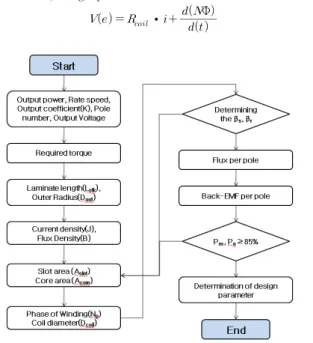
Basic outer dimension of TFSRG is decided by using output equation(1).

  ⨉ 

∙ 



(1) Where diameter of rotor(Dr) is same one of TFSRG and stack length(Lstk) is thickness of rotor. Equation(2) is for maximum mmf per pole.

∙



  





(2)

Where maximum/average ratio of mechanical output and electrical

output is defined about 2.25 and flux density(Bs) is 1.7T. After

consider maximum/average ratio to calculate maximum mmf per

pole, we can also calculate effective mmf per pole. If slot fill factor

is assumed 90%, cross sectional area of winding, turns per pole

and diameter of coil can be obtained. And considering mechanical

output and flux density from equation (2), cross sectional area of

core can be calculated too. Inner dimension of TFSRG is obtained

by considering the area of winding and core, pole arc of stator

and rotor considering inductance of proposed structure. Induced

emf and flux per pole can be decided from magnetic circuit and

voltage equation (3). And, when electric output obtained by

2011년도 대한전기학회 하계학술대회 논문집 2011. 7. 20 - 22

(2)

- 946 -

induced emf is compared with mechanical output, if efficiency is more than 85%, design process will be finished.

   



∙ 



  Φ

(3)

<Fig 3> Design process of TFSRG

<Table 1> Proposed specification and design dimension of TFSRG

Motor parameter Unit Value

Output powe(rated) W 3000

Torque(rated) Nm 57.3

Speed(rated) rpm 500

Current(rated) A 8

The number of pole of stator p 24

The number of pole of rotor p 24

Air gap mm 0.3

Stator pole arc ° 7.69

Rotor pole arc ° 5.15

Outer diameter of stator mm 370

Outer diameter of rotor mm 269.4

Stack length mm 50

Stator pole width mm 18.1

Rotor pole width mm 12.1

2.3 CHARACTERISTIC ANALYSIS

3D FEM be used for accurate characteristic analysis of the machine. And Fig. 4(a) shows the analysis results. Torque characteristics be checked when speed is 1[RPM] and current is rated current 8[A]. Average torque which is obtained by output equation is calculated 57.3[Nm] by using output power 3kW of objective specification. And when speed is also 1[RPM], the maximum torque of simulation result is 56.2[Nm]. This relation can derive from assumption that mechanical output equals electrical output.

(a) Torque

(b) Inductance

<Fig 4> Characteristic of TFSRG with rated current(8A) (Rotation Speed : 1[RPM])

Fig. 4(b) shows magnetic inductance in sending rated current to coil A. Maximum and minimum of magnetic inductance is needed to know. Because In theory, If the current is sent when Inductance is reduced, accumulated magnetical energy as well as mechanical energy due to negative torque is returned to source. So regenerative breaking can be in quadrant Ⅱ and

Ⅳ. Therefore the current must be sent when the magnetic inductance for coil A is maximum and we have to switch off the current when the magnetic inductance is minimum.[5]

Table 2 shows maximum and minimum of the magnetic inductance.

<Table 2> maximum and minimum of the magnetic inductance in sending rated current to coil A

Parameter Unit Value

Inductance(MAX) mH 189.5

Inductance(MIN) mH 62.6

3. CONCLUSION

This paper suggests three phase TFSRG for direct-drive generator system types. The dimension of TFSRG is obtained by objective specification. And the specification is also confirmed by solving simulation modeling using electric equivalent circuit. Then we performed characteristic analysis through FE-analysis. Design process and analysis method is obtained from mathematical analysis derived by the assumption that mechanical output equals electrical output.

This assumption is verified by the results which are obtained by using 3D FE-analysis. If this design dimension and analysis results are used, dynamic characteristic results can be analyzed by using matlab simulation method. And then results can be more accurate through optimum design and experiment.

This research was supported by WCU (World Class University) program through the National Research Foundation of Korea funded by the Ministry of Education, Science and Technology (R33-2008-000-10104-0)

[REFERENCE]

[1] H. Polinder etal"Comparison of direct-drive and geared generator concepts for wind turbines," IEEE Transaction on Energy Conversion, Volume 21, Issue 3, pp.725·733, Sept 2006.

[2] R. Kruseetal"Transverse flux reluctance motor for direct servodrive applications," Industry Applications Conference, 1998. The 1998 IEEE, Volume 1, pp.655·663, 12-15 oct 1998.

[3] S. M. Jang"Deduction of characteristic analysis and circuit parameter for SRM circuit design" spring conference of KIEE electric machinery and energy conversion system, Volume 1, pp53-55, April 2007.

[4] H. M. Amireiz"A comparison between transverse flux and conventional switched reluctance machines"International Conference on Electrical Machines, Volume 1, Issue 6, pp 308-315, Sept 2010.

[5] H. Chen and J. J. Gu "Implementation of the Three-Phase Switched

Reluctance Machine System for Motors and Generators"IEEE/ASME

Transactions on Mechatronics, Volume 15, No. 3, pp 421-432, June

2010.

수치

Table  2  shows  maximum  and  minimum  of  the  magnetic  inductance.

참조

관련 문서

This will involve the solution of (n+1) linear systems.. Write a routine that determines the flux at each region and currents at the external boundary. Generate the edit shown

The magnetic flux leakage inspection method is more advanced than the magnetic particle inspection method in terms of quantitative evaluation and can detect flaws and

 A series of systems for configuring alarm and control functions by monitoring the states of main engine, generator, and auxiliary equipment, for securing the safety

- flux of solute mass, that is, the mass of a solute crossing a unit area per unit time in a given direction, is proportional to the gradient of solute concentration

The aim of this work was to prepare tenoxicam-ethanolamine salt with improved physicochemical properties, to compare the flux of tenoxicam and

radial pressure balance, toroidal force balance, β limits, q-profiles, etc.. - The stream function ψ is closely related to the poloidal flux

Park, “NDT of a nickel Inconel specimen using by the complex induced current - magnetic flux leakage method and linearly integrated hall sensor array”, Journal of the

Mirzaeian, &#34;Intelligent Automated Optimal Design of Switched Reluctance Motor Using Genetic-Fuzzy Algoritnms&#34;, Record of the 13th COMPUMAG Conference on