제8권, 제5호 (2009년 10월) pp. 114~120
Performance Analysis of Optical Path Difference on Visible Light Communication System
for Intelligent Transport Systems
최 재 혁* 이 계 산** 차 재 상*** 김 진 영****
(Jae-Hyuck Choi) (Kye-San Lee) (Jae-Sang Cha) (Jin-Young Kim)
Abstract
In outdoor visible light communication channels and LED road illumination communications for the intelligent transport systems (ITS), inter symbol interference (ISI) due to multipath propagation prevents high data rate transmission. Indoor wireless optical communication systems utilizing white LED lights and on the road illumination have been studying about it. Generally, plural lights are installed in room and considered to the traffic information system using existing LED traffic lights. Therefore, their optical path difference must be considered. In this paper, the influence of an optical path difference has been investigated and two approaches against this problem are introduced. One uses on-off keying, return-to-zero (OOK-RZ) coding and the other uses optical orthogonal frequency division multiplexing(OFDM).
Key words: Lights layout, OFDM(Orthogonal frequency division multiplexing), OOK-RZ(On-off keying, Return-to-zero),
Visible-Light Communication(VLC), White LED
* 주저자 : 광운대학교 전파공학과 석사과정 ** 공저자 : 경희대학교 전파공학과 조교수 *** 공저자 : 서울산업대학교 매체공학과 조교수
**** 공저자 : 광운대학교 전파공학과 부교수
†논문접수일 : 2009년 10월 5일
†논문심사일 : 2009년 10월 20일
†게재확정일 : 2009년 10월 23일
Ⅰ. Introduction
In the age of the 4th generation communication system, high speed data transmission will play an important part in our life. We will be able to transmit many kinds of information, which are so called multi- media information, at any place and any time. Therefore, the concept of wireless indoor link such as home or office has been proposed and drawn considerable attention.
The electrical appliances will be wireless-linked with
each other in the future, and using wireless home link, we will be able to access communication each other with these appliances anywhere in indoor environment [1]. Specially, a visible light communication (VLC) system can be considered as a candidate for wireless indoor link [2, 3]. The VLC is suitable for wireless indoor link because it uses illumination device already installed. And we have proposed a wireless optical communication system utilizing white LEDs for wireless home link. In this system, lighting equipment
<Fig. 1> General lambertian radiation pattern
<Fig. 2> Geometry of transmitter and receiver is able to have a capacity for wireless optical commu-
nication. An optical path difference must be considered when plural lights are utilized. Thus here, the influence of an optical path difference has been investigated and two approaches against this problem are introduced.
One uses On-Off Keying, Return-to-Zero (OOK-RZ) coding and the other uses optical Orthogonal Frequency Division Multiplexing (OFDM) [4]. Through computer simulations, we found that these approaches are feasible for the wireless optical link utilizing white LEDs.
This paper is organized as follows. In section 2, introduces the proposed system model and Section 3 shows the simulation results and discussions. Finally, we give our conclusions in section 4.
Ⅱ. System Model
1. Transmitter and Receiver model
A transmitter can be represented by a position vector
, a power
, and a radiation intensity pattern∅
, defined as the optical power per unit solid angle emitted from the transmitter. Following in [5], we model a transmitter using a general Lambertian radiation pattern as follow (1).∅
∅ ∅∈
(1)where, n is the mode number of the radiation robe, which specifies the directionally of the transmitter. As shown in Fig. 1, transmitter has higher directionality with lager mode number.
The coefficient
ensures that integrating∅
over the surface of a hemisphere results in the source power
. A mode number n=1 corresponds to a traditional Lambertian source. To simplify notation, a point transmitter S that emits a unit impulse response of optical intensity at time zero will be denote by an ordered three-tuple in,
(2)where,
is its position,
its orientation, and n is its mode number. Similarly, a receiver element R with position
, orientation
, area
, and field of view (FOV) is denoted by an ordered four-tuple, Fig. 2 shows geometry
(3)of transmitter and receiver in (2) and (3). The scalar angle FOV is defined such that a receiver only detects light whose angle of incidence is less than FOV.
2. Channel Model
Consider a transmitter and receiver, as represented above (1) and (2), in indoor environment with guarantee line of sight (LOS) condition. If the distance
R between transmitter and receiver is much larger than area
≫
, then the received irradiance is approximately constant over the surface of the receiver, and also, all of signal is considered that arrive at the same time at the receiver. As following above approximation, the impulse response is simple a scaled and delayed Dirac delta function as follow in [6].
∅Ω
(4)where,
is the solid angle subtended by receiver’s differential area,Ω≈
(5)R is the distance between the transmitter and receiver,
∥
∥
(6)
is the angle between
and
,
∙
(7)∅
is the angle between
and
, ∅
∙
(8)And the rectangular function is defined as follow,
≤
(9)In (4), c is denoted by speed of light. Using above impulse response of LOS condition, multi bounce impulse response can be calculated easily by as follow.
∞
(10)where,
is the response of the light under going exactly k reflections. Using LOS impulseresponse
in(4), higher order term(k>0)
in (10) is represented as follow.
⊗
(11)where,
⊗
is denoted convolution sum. More exactly, substituting (4) for (11) and performing the convolution sum results in
∅
(12)
The integral in (11) and (12) can be calculated numerically by discontinuous reflecting surfaces into numerous small reflecting elements, each with
. Therefore, (11) and (12) can be represented as follow.
≈
⊗
∅
(13)
3. Optical path difference
In the proposed system which utilizes multiple lights, an optical path difference must be considered. This is caused by delay time due to plural transmitters as shown in Fig. 3. When two transmitters are assumed to be used, a ratio of delay to pulse width is where c is the speed of light and
[bps] is the rate of optical pulses. The meaning of other abbreviations is shown in Fig. 3.
(14)Optical signals are arrived at a terminal through two directed LOS paths. In simulation, the situation
<Fig. 3> Pulse delay due to an optical path difference
<Fig. 4> OOK-RZ coding with alleviation of a delay effect
<Fig. 5> OFDM system described in Fig. 6 is assumed. The width between two
transmitters w is 5.0[m] and the height of room h is 3.0[m].
From this figure, it is found that the delayed signal degrade the performance when a terminal is distant from a optical transmitters.
When the terminal is set just under a transmitter, the floor can be seen and we cannot communicate.
4. OOK-RZ and Optical OFDM
In this paper, two approaches against this problem are discussed. An OOK-RZ (On-Off Keying Return-to-Zero) coding is considered as a candidate for alleviating the optical path delay. Ordinary OOK utilizes the conti- nuous pulses, whereas “1” pulses have a period being zero in OOK-RZ coding. This is shown in Fig. 4.
Thus, the ratio r is defined in this paper as:
. (15)
As shown in Fig. 4, the OOK-RZ coding has a guard time and can alleviate a delay effect. These pulses require a wide transmission bandwidth.
However, this is not significant because an optical carrier has wide bandwidth available.
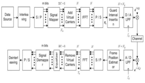
Another approach is the one using OFDM (Orthogonal Frequency Division Multiplexing). In an optical OFDM system, the delay is absorbed by a guard interval of an OFDM symbol. The system is shown in Fig. 5, in which T transmitters are assumed. The original data bits are copied to each transmitter, which is composed of LEDs. In each transmitter, an information sequence is converted to N parallel symbols with S/P (serial to parallel) converter and modulated in each branch. Then the modulated parallel symbols are converted into the sum of N different subcarriers by IFFT (Inverse Fast Fourier Transform) and guard intervals are inserted.
This is the way how OFDM signals are generated.
These signals are converted into optical intensity by an O/E (optical to electrical) converter, and finally emitted into the air. At a terminal, the received light wave is converted into an electrical waveform by a PD. This waveform, which is an OFDM modulated signal, is demodulated by OFDM demodulator and the original data bits are retrieved.
Ⅲ. Symulation Results
Table 1 is represented simulation parameters for
Parameter A
Room
Length(x) 5m
Width(y) 5m
Height(z) 3m
Source
Mode 1
X 2.5
Y 2.5
Z 3
Receiver
Area 1cm
FOV 60
X 1
Y 1
Z 0
Transmitted optical power 1W Reflection index wall : 0.9
Resolution
T 2ns
bounces 1 2
Nx 500 100
Ny 500 100
Nz 300 60
<Table 1> Simulation parameters
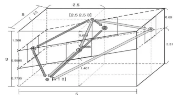
<Fig. 6> Simulation environment with multi bounce
<Fig. 7> Impulse response of multi bounce calculation LOS and multi bounce received signal. We
set up the indoor room size with 5m length (x-axis), 3m width (y-axis) and 3m height (z-axis) where it is designed in rectangular coordinate system. Position of transmitter and receiver are (2.5m, 2.5m 3m) and (1m, 1m, 0m) as illustrated in Fig. 6. Mode number of transmitter in (1) is fixed by “1”, FOV of receiver in (5) is 60 degree and received area AR is 1cm. So, using above parameters of mode number, FOV and received area, we can calculate valid reflecting area from ① to ④ which illustrated in Fig. 6. Receiving signal which bounced outside of valid reflecting area is
not considered. We control the power of transmitted signal is 1W and it is transmitted to all direction and the attenuation coefficient of each reflecting walls is fixed 0.9 (0.9 is concrete’s attenuation coefficient). And the parameter “T” is the bin width of the power histogram that approximates the impulse response, so, received signals within time “T” are just summed at the receiver.
In this paper, we consider only the first order reflected signal, that is
, because of, the calculation complexity of higher order (k>1) impulse response is very high and received power of higher order(k>1) impulse response is very low.Fig. 7 shows the impulse response of
based simulation parameters. X-axis represents simulation time and y-axis represents power of received signal. A reason of existing four impulse responses is that each impulse is affected by different time delay and power attenuation due to difference of distance between the transmitter/receiver and reflecting point at four vertical walls. The dominant impulse response is the reflected signal at reflecting region ③ and the last impulse response is the reflected signal at reflecting region ④.Using the impulse response in Fig. 7, the final received signal is obtained by convolution sum between impulse response and line coded signal at the receiver and it is represented in mathematical form as follow.
⊗
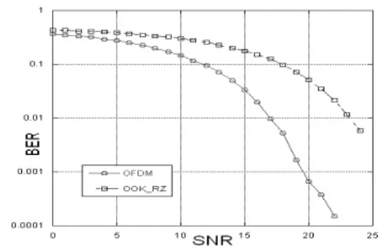
. (16)<Fig. 8> Comparison of OOK-RZ with OFDM coding
where,
is received signal,
is line coded input signal,
is impulse response and
is the additive white Gaussian noise (AWGN).Fig 8 shows the BER performance of compared an OOK-RZ coding versus and an optical OFDM system.
These results show us that the guard interval of optical OFDM can improve the performance in proposed system. We also can know that OFDM with guard intervals has the effect for the high speed data transmission.
Ⅳ. Conclusions
Indoor wireless optical communication systems utilizing white LED lights have been proposed. An optical path difference, however, must be considered in this system when plural lights are assumed to be utilized. In this paper, the influence of an optical path difference has been investigated and two approaches (OOK-RZ, OFDM) to reduce the delay have been introduced. It was found from the computer simulation results that delay due to an optical path difference affects the performance when the original data rate is
high. OFDM with guard intervals has the effect for an optical path difference in high speed data transmission.
A high data rate transmission will be required in the future and thus this delay problem needs to be solved.
We are expecting indoor visible light communication system utilizing white LEDs as an indoor LAN system of the next generation. Further research on these would make an LED light communication feasible.
Reference
[1] J. M. Khan and J. R. Barry, “Wireless infrared communications,” Proc. of IEEE, vol. 85, no. 2, pp. 265-298, Feb. 1997.
[2] T. Komine and M. Nakagawa, “Fundamental analysis for visible-light communication system using LED lights,” IEEE Trans. Consumer Electron., vol.
50, no. 1, pp. 100-107, Feb. 2004.
[3] J. Grubor, J. O. Gaete, J. Waleski, S. Randel, and K. Langer, “High-speed wireless indoor commu- nication via visible light,” ITG Bachbericht, pp.
203-208, 2007.
[4] R. V. Nee and R. Prasad, OFDM for Mobile Multimedia Communications, Artech House, London, 2000.
[5] F. R. Gfeller and U. H. Bapst, “Wireless in-house data communication via diffuse infrared radiation,”
Proc. of IEEE, vol. 67, no. 11, pp. 1474-1486, Nov. 1979.
[6] J. R. Barry, J. M. Kahn, W. J. Krause, E. A. Lee, and D. G. Messerschmitt, “Simulation of multipath impulse response for indoor wireless optical channels,” IEEE J. Select. Areas Commun., vol.
11, no. 3, pp. 367-380, Apr. 1993.
저자소개 최 재 혁 (Choi, Jae-Hyuck)
2008년 : 광운대학교 전파공학과 공학사 졸업 2009년 ~ 현재 : 광운대학교 전파공학과 석사 과정
이 계 산 (Lee, Kyesan)
1996년 : 경희대학교 전자공학과 졸업 1999년 : 일본게이오대학교 전기공학과 석사 2002년 : 일본게이오대학교 정보통신공 학과 박사 2002년 : 일본(주)KDDI 연구소 근무
2003년 : 일본게이오대학교 전임강사
2003년 ~ 현재 : 경희대학교 전자전파공학과 조교수
차 재 상 (Cha, Jae-Sang)
2000년 : 일본 東北대학교 전자공학과 공학박사
2002년 : ETRI 이동통신연구소 무선 전송기술팀 선임연구원 2008년 : 미국 플로리다 대학교 방문교수
2002년 ~ 2005년 : 서경대학교 정보통신공학과 교수 2005년 ~ 현재 : 서울산업대학교 매체공학과 조교수
김 진 영 (Kim, Jin-Young)
1998년 : 서울대학교 전자공학과 공학박사
2000년 : 미국 Princeton University, Research Associate 2001년 : SK 텔레콤 네트웍연구원 책임연구원 2001년 ~ 현재 : 광운대학교 전파공학과 부교수 2009년 ~ 현재 : 미국 M.I.T 공대 Visiting Scientist