Copyright
Ⓒ2018 KSAE / 156-04 pISSN 1225-6382 / eISSN 2234-0149
DOI https://doi.org/10.7467/KSAE.2018.26.5.590Transactions of KSAE, Vol. 26, No. 5, pp.590-597 (September, 2018)
대형버스 루프 스포일러의 공력 및 공조 성능 개선을 위한 해석적 연구
김 민 호*
현대자동차 상용해석팀
A Numerical Simulation of a Roof Spoiler for Aerodynamic and Air-conditioning Performance Improvement in a Large-sized Bus
Minho Kim*
Commercial Vehicle CAE Team, R&D Division, Hyundai Motor Company, 150 Hyundaiyeonguso-ro, Namyang-eup, Hwaseong-si, Gyeonggi 18280, Korea
(Received 6 November 2017 / Revised 7 March 2018 / Accepted 8 May 2018)
Abstract : The roof spoiler design of a commercial bus has a significant impact on aerodynamic performance. In this study, numerical simulations have been carried out in order to investigate the effect of a front-spoiler that is attached at the front of a bus body. First, wind tunnel tests were performed on a 1/4 scale bus model to verify the effectiveness of a digital wind tunnel. In this stage, prediction results on the drag coefficient and surface pressure on the center line of a bus body were compared with those of wind tunnel tests. Second, numerical simulations have been carried out for the actual bus model with a detailed air conditioning system to evaluate aerodynamic drag and the effect of ventilation. As a result of this study, it was confirmed that simulation results regarding surface pressure and drag force work well with wind tunnel test results. In particular, the effect of the front spoiler on the drag and flow behavior around an air conditioning system was investigated. The improved roof spoiler design also showed that the aerodynamic drag of a large-sized bus could be reduced by 5 %.
Key words : Digital wind tunnel(디지털 풍동), Bus body(버스바디), Roof spoiler(루프 스포일러), Scale model(축 소 모델), Aerodynamic drag(공기저항력)
1. 서 론1)
자동차 주위의 공기흐름은 복잡한 난류유동으로 써 유선화된 외형설계를 통해 공기저항을 감소시켜 연료를 절감하는 경제성 측면과 양력 및 횡풍 영향에 의한 조정 안정성 측면에서 중요한 의미를 갖는다.
이 중에서 공기저항은 연료량의 증가를 야기하므로 차량 개발시 설계 초기단계에서 공력성능을 평가하 기 위한 연구들이 주로 수행되고 있다. 특히 장거리
운송수단으로 자리 잡은 고속버스의 경우에는 공기 저항이 연비에 지대한 영향을 미치므로 최근에는 저 저항 형상도출 및 항력저감을 위한 부착장치에 대한 관심이 대두되고 있다. 설계 초기단계에서는 자동차 의 외형에 따른 공기저항 예측을 위해 주로 모형을 이용한 풍동 실험을 수행하고 있으나 차량 주위 유동 장의 자세한 정보를 얻기 위해서는 실험장치 구성 및 모형제작을 위한 많은 비용이 소비되며 개발기간 또 한 오랜 시간 소요되는 단점이 있다.
*
A part of this paper presented at the KSAE 2012 Spring Conference
*
Corresponding author, E-mail: [email protected]
* This is an Open-Access article distributed under the terms of the Creative Commons Attribution Non-Commercial License(http://creativecommons.
org/licenses/by-nc/3.0) which permits unrestricted non-commercial use, distribution, and reproduction in any medium provided the original work is properly cited.
대형버스 루프 스포일러의 공력 및 공조 성능 개선을 위한 해석적 연구
최근 들어 전산기 용량의 성장 및 수치해법의 비약 적인 진보로 인해 CFD(Computational Fluid Dynamics) 기법을 활용하여 차량 개발 기간을 단축하고 실험 을 통해 얻기 힘든 많은 유용한 정보들을 얻고 있으 나 지금까지의 연구들은 주로 승용차에 국한되며 버스나 트럭과 같은 상용차에 대해서는 아직 미흡 한 실정이다.
대형버스의 경우에는 주로 타행시험에 의존하고 있지만 일관된 시험조건 재현이 어렵고 타행 시험 만으로는 유동장에 관한 상세정보를 획득하기 난해 하므로 대형버스의 공기저항 개선을 위한 전반적인 이해를 도모하기 힘든 실정이다.1-8)
기존의 상용차에 대한 연구들을 살펴보면 Takemori 등9)은 단순화된 1/16 축소 버스모델의 후미에 가이 드 베인 부착형태에 따른 항력계수와 표면 압력분 포 등을 고찰하여 항력 저감을 위한 효과적인 후류 제어(Wake control)에 관한 연구를 수행하였고 다.
심대영 등10)은 공기저항 감소장치의 형상변경에 따 른 항력계수를 계산하였다. Perzon 등11)은 단순화된 트럭모델에 대하여 해석 스킴과 난류모델에 따른 항력계수 및 압력 분포결과와 실험결과를 비교 분 석하였고 김철호와 이승현12), Abdel 등13)은 버스모 델 외관 형상변화와 레이놀즈수 변화에 따른 압력 분포 등을 고찰한 바 있다. 이와 같이 기존의 연구들 은 주로 단순모델을 이용하여 항력계수를 예측하였 고 실제모델을 이용하더라도 항력저감과 공조성능 을 고려한 루프 스포일러에 대한 연구는 아직 미진 한 실정이다.
본 연구에서는 1/4스케일 모델을 이용한 풍동 시 험결과와 디지털 풍동을 이용한 해석결과를 비교하 여 디지털 풍동의 유효성을 검증한 후 실제 주행조 건에서 공력특성을 고찰하였다. 디지털 풍동을 활 용한 본 연구를 통해 실차 시험시 획득하기 힘든 유 동장에 관한 상세정보를 얻을 수 있었으며 실차 풍 동 시험과의 비교를 통해 고정도의 상용차 전용 디 지털 풍동을 구축하였다. 또한 공조시스템의 유입 구를 고려한 프런트 스포일러 개발을 통해 항력 저 감과 공조 풍 유입 및 유출 특성에 대한 이해를 도모 하였다.
2. 정밀 디지털 풍동 구축 2.1 해석모델 및 조건
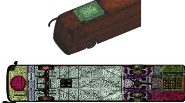
전산 해석에 있어서 많은 시간이 소요되는 과정 은 계산격자 생성 절차인데 기하학적 모델 생성을 위하여 ANSA S/W를 이용하였다. Fig. 1에는 실차 공력해석을 위한 차량 형상 데이터를 도시하였다.
차량 하부형상을 상세하게 고려하였으며 공력에 영 향을 줄 수 있는 미세 단차 등의 실제 형상을 그대로 반영하였다. 이산화 과정 이후 생성된 각 영역의 3 차원 격자(Voxel)는 Fig. 2와 같다. 프런트 바디 곡률 부 및 미세 단차를 고려하기 위하여 이 영역에는 1.25 mm를 부여하였고 미러와 리어 바디 곡률부 그 리고 공조시스템 개구부 영역에는 2.5 mm로 하였 다. 프런트 바디 전면과 공조시스템 그리고 미러 후 류 영역은 5 mm, 바디 인접 영역과 후류 영역은 10 mm로 모델링하여 복잡한 후류 난류 흐름을 모사할 수 있도록 하였다. 격자 사이즈가 변경되는 각 영역 설정을 위해서는 임의의 값에 대한 3차원적인 전압 구배 표면을 사전해석을 통해 추출한 후 이 표면을 충분히 포함할 수 있도록 각 영역을 설정하였다.
Fig. 1 3D view of the model bus and the optimized numerical grid at the bottom of the model
Fig. 2 The optimized numerical grid with the find grid embedded in the numerical domain around the bus model
Minho Kim
차량 전체를 감싸는 영역의 크기는 격자 민감도 해석을 통해 차량 상류 방향으로는 차량높이의 1배, 하류는 3배, 차량 폭과 높이 방향은 각각 0.3배로 하 였다.
2.2 정밀 디지털 풍동 유효성 검증
디지털 풍동의 신뢰성을 검토하고자 먼저 Ahmed body 모델과 1/4스케일 버스 모델을 제작하여 풍동 시험 결과와 비교하였다. Fig. 3과 같이 풍동 시험시 타이어 회전 및 이동지면을 재현하여 실제 주행조 건을 반영하였다. 본 연구에서 사용된 PowerFLOW 코드는 디지털 물리학에 기초한 전산유체역학 코드 로서 Lattice Boltzmann Method(이하 LBM)14)을 근간 으로 한 유동 입자의 이송 및 충돌에 의한 상호 작용 관계를 구현한다. 상기 코드는 수치적 소산이 매우 적은 미시적인 유동구조를 모사하기 위해서 질량과 운동 량의 실제적인 이송을 다루는 이상 기체 방정 식과 LBM를 연성하여 해를 구하는 방식을 채택하 고 있다. 따라서 기존의 이산화된 편미분 방정식을 활용한 범용코드에 비해 시간변화에 따른 미시적인 유동구조를 잘 모사할 수 있는 장점이 있다.15)
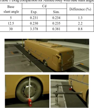
Table 1 Drag comparison for Ahmed body with base slant angle Base
slant angle
Cd Difference (%)
Exp. Sim.
5 0.231 0.234 1.3
12.5 0.230 0.235 2.2
30 3.378 0.381 0.8
Fig. 3 1/4 scale bus model installed at the test section for the wind tunnel test with the moving ground condition
Fig. 4 Comparison of Cp of the experiment to the numerical outcomes at the upper surface of the base bus model
Table 1에는 Ahmed body의 후미 경사각(Base slant angle) 변화에 따른 항력계수를 비교하였다. 이에 대 한 자세한 제원은 참고문헌16)에 잘 나타나 있으며 전반적으로 해석결과가 2.2 % 이내로 잘 일치함을 볼 수 있다. Fig. 4에 도시한 바와 같이 1/4 스케일 버 스 모델의 표면 압력계수는 해석과 시험결과가 매 우 유사한 결과를 보였고 1 m2의 단면적을 기준으로 한 항력계수 해석결과는 0.2586이고 시험 결과는 0.2652로 약 2.5 % 차이를 보여 매우 잘 일치하는 결 과를 나타내었다.
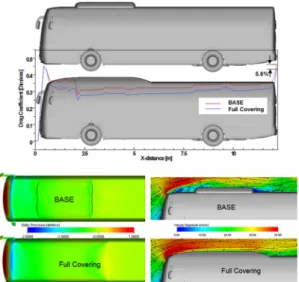
3. 디지털 풍동해석 3.1 루프 스포일러 공력 퍼텐셜 고찰 대형버스 공력 개선을 위하여 루프 공조 시스템 을 유선화한 이상적인 루프 스포일러에 대해 공력 개선 최대 퍼텐셜(Potential)을 고찰하였다. 공력 퍼 텐셜은 최대 저감 가능한 항력 수준을 의미한다.
Fig. 5에 도시한 바와 같이 루프 공조 시스템 유선 화 안의 경우에는 약 5.6 % 항력 저감이 가능하였고 프런트 바디 상단 곡률부에서 발생하는 와류를 제 거함으로써 이 영역에 작용하는 고압형성 영역이 상대적으로 감소되었고 또한 유선화된 스포일러 면 을 따라 원활한 흐름이 형성되고 있다.
3.2 스포일러 형상에 따른 공력 효과 고찰 프런트 루프 스포일러 외관 형상을 결정하고자 첫 단계로 유입구가 고려되지 않은 스포일러 형상 에 대한 공력특성을 고찰하였다. 대형버스 에어컨 시스템은 루프 위에 위치하며 1-unit, 2-unit 두 가지 방식이 있으며 2-unit는 1-unit에 비해 폭이 작고 길 이가 긴 형상이다. Fig. 6에는 프런트 스포일러 형상
A Numerical Simulation of a Roof Spoiler for Aerodynamic and Air-conditioning Performance Improvement in a Large-sized Bus
Fig. 5 Drag force development along the vehicle length and change of pressure & velocity distribution in case of model with full cover
(a) D1 front spoiler
(b) D2 front spoiler
Fig. 6 Initial design of front spoiler according to the variation of the air conditioning unit
을 도시하였다. 프런트 스포일러 초기 형상 설계시 스포일러 앞부분은 1-unit와 2-unit 두 모델에 모두 적용 가능하도록 공용화하였고 2-unit 경우에만 마 름모 형태의 추가적인 연결 패널을 두어 공조시스 템 전방 인접 영역까지 유선화 할 수 있도록 하였다.
D1 대비 D2 형상은 바디 측면까지 감싸는 형상이다.
루프 스포일러 및 에어컨 유닛 변화에 따른 수직 단 면에서의 속도 분포를 Fig. 7에 도시하였고 Table 2
Table 2 Drag reduction rate for front spoiler shape
Model Cd×A Drag reduction (%)
Base 1-unit 3.760
2-unit 3.877 Ref.
D1 1-unit 3.622 3.7
2-unit 3.639 6.2
D2 1-unit 3.596 4.4
2-unit 3.619 6.7
(a) D1 front spoiler
(a) D2 front spoiler
Fig. 7 Velocity distribution of D1 & D2 front spoiler at the vertical section
에는 공력결과를 나타내었으며 A는 차량의 투영 단 면적을 의미한다.
스포일러를 장착한 경우 2-unit 모델의 항력 저감 이 보다 크게 발생하였고 D1 스포일러 대비 D2 포 일러를 장착한 모델의 공기저항이 보다 개선되었 다. D2 스포일러를 장착한 2-unit 모델의 공기저항은 6.7 % 개선되었다. 이는 Fig. 5와 Fig. 7에 도시한 속 도분포에서 볼 수 있듯이 전반적으로 프런트 바디 루프 곡률부에서 발생하는 와류가 스포일러 장착으
김민호
로 인해 현저하게 소멸되었고 바디끝단까지 감싸는 D2 스포일러 적용시 와류에 의한 에너지 손실 영역 이 보다 저감되었기 때문이다.
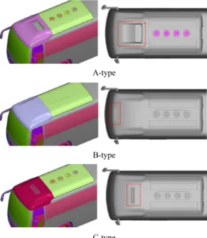
3.3 외기 유입구를 고려한 스포일러 설계 전 절에서 기술한 루프 스포일러 외관형상 설계 안 중 공력특성이 보다 우수한 D2안에 대해 외기 유 입구를 고려한 상세설계를 수행하였다. Fig. 8에 도 시한 바와 같이 공조를 위한 외기 도입구 위치 및 형 상 변경에 따른 세 가지 형태의 스포일러를 고려하 였다. 먼저 주행시 공조팬이 작동되지 않는 조건에 서 공력특성과 공조 풍량 유입특성을 고찰하였다.
A-Type은 스포일러 상면 중앙부에 외기 유입구를 적용한 안이고 B–Type은 스포일러 상면 전방에, C-Type은 스포일러 상면 중앙부에 슬롯형태의 외기 유입구를 적용한 안이다.
Fig. 9에 도시한 바와 같이 A-Type과 C-Type은 루 프 에어콘 상부에서 형성되는 와류영역이 거의 소 멸되어 있다. 속도결손 측면에서는 C-Type이 가장 유리한 흐름을 나타내었고 B-Type의 경우 스포일러 전면에 있는 외기 유입구로 역류하는 흐름이 발생 하여 스포일러 상면에 재순환 유동이 형성되어 외기 유입구 이후 와류발생 및 속도 결손이 상대적으
A-type
B-type
C-type
Fig. 8 Detailed design of front spoiler for 1-unit system
로 크게 발생하고 있다. 2-unit 모델의 경우 1-unit 모 델에 비해 전반적으로 재순환 유동 및 속도 결손이 증대됨을 볼 수 있다.
Fig. 10에는 공조 시스템 내부의 Z단면 속도분포 와 스트림라인을 도시하였다. 1-unit 모델의 경우 A-Type은 앞쪽 및 뒤쪽 외기 도입구 모두 공조시스템 내부로 유입되는 흐름이 관찰되고 있으며 B-Type,
(a) 1-unit
(b) 2-unit
Fig. 9 Velocity distribution according to the variation of front spoiler type
(a) 1-unit
(b) 2-unit
Fig. 10 Velocity distribution inside front spoiler according to the variation of front spoiler type
대형버스 루프 스포일러의 공력 및 공조 성능 개선을 위한 해석적 연구
Table 3 Drag reduction rate in case of 1-unit system
1-unit Cd×A Drag reduction (%)
BASE 3.784 Ref.
A-Type 3.624 4.2
B-Type 3.672 3.0
C-Type 3.607 4.7
Table 4 Drag reduction rate in case of 2-unit system
2-unit Cd×A Drag reduction (%)
BASE 3.901 Ref.
A-Type 3.693 5.3
B-Type 3.693 5.3
C-Type 3.677 5.8
C-Type 모두 앞쪽 외기 유입구에서 유출되는 흐름 이 형성되었다. 2-unit 모델의 경우에도 1-unit 모델 과 동일하게 앞쪽 외기 유입구에서 A-Type은 유입 이 되고 B-Type 과 C-Type은 유출 되는 흐름이 형성 되고 있다.
공조 팬이 작동하지 않는 조건에서 항력계수는 Table 3과 Table 4에 도시한 바와 같이 C-Type이 1-unit, 2-unit 모두 가장 우수하나 외기 유입특성은 A-Type에 비해 불리한 구조임을 알 수 있다. 반면 A-Type은 공기저항과 자연 외기 유입 특성이 모두 개선되었다.
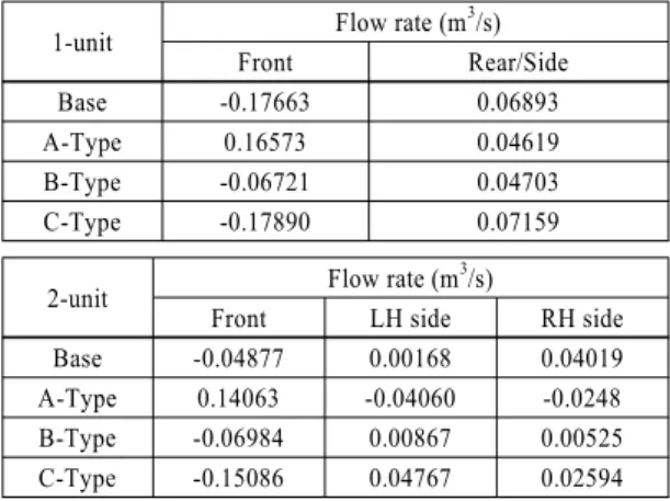
3.4 외기 주행풍에 의한 각 유입구 풍량 비교 Fig. 11과 Table 5에는 주행풍에 의한 공조시스템 의 외기 유출입 개략도를 도시하였고 스포일러 형 상 변경시 각 외기 도입구에서의 풍량을 나타내었 다. Table 5에 나타낸 수치의 음의 값은 공기 유출을 의미하고 양의 값은 공기유입을 의미한다. 스포일 러가 없는 Base 모델은 에어컨 유닛 변화에 상관없 이 모두 앞쪽 개구부에서는 유출되는 유동이 형성 되고 있으며 1-unit 모델의 뒤쪽 개구부와 2-unit 모 델의 좌우측 개구부에서는 유입되는 흐름이 형성 된다.
반면 A-Type 스포일러를 장착한 1-unit 모델은 앞 뒤쪽 개구부에서 모두 유입되는 흐름이 형성되며 2-unit 모델은 앞쪽 개구부에서는 유입되고 좌우측 개구부에서는 유출되는 흐름이 형성되고 있다. 이 는 Fig. 5와 Fig. 10에 도시한 스포일러 장착전의 흐
BASE A-Type
B-Type C-Type
Fig. 11 Schematic illustration on the inflow & outflow around each opening area under fan-off condition
Table 5 Air mass flow rate at each opening region 1-unit Flow rate (m3/s)
Front Rear/Side
Base -0.17663 0.06893
A-Type 0.16573 0.04619
B-Type -0.06721 0.04703
C-Type -0.17890 0.07159
2-unit Flow rate (m3/s)
Front LH side RH side
Base -0.04877 0.00168 0.04019
A-Type 0.14063 -0.04060 -0.0248
B-Type -0.06984 0.00867 0.00525
C-Type -0.15086 0.04767 0.02594
름에서 볼 수 있듯이 공조시스템 앞쪽영역에서 재 순환유동이 형성되어 이러한 흐름의 영향으로 주행 풍이 유입되지 못하고 유출되는 흐름이 생성되기 때문이다. A-Type 스포일러 장착시에는 이러한 재 순환 유동이 소멸되어 앞쪽 개구부에서도 유입되는 것으로 사료된다. B-Type과 C-Type 스포일러 장착 시에는 앞쪽 개구부에서는 모두 유출되며 뒤쪽과 좌우측 개구부에서는 유입되는 흐름이 형성되어 스 포일러 장착전과 동일한 흐름 구조가 형성됨을 알 수 있다.
Minho Kim
3.5 팬 회전에 의한 공조 풍량 고찰
공조팬 작동시 외기 유출입 경로와 흐름을 Fig. 12 와 Fig. 13에 도시하였다. 팬이 작동되지 않고 주행 풍만 있는 경우에 비해 팬 작동조건에서 1-unit 모델 의 경우 스포일러 장착 유무에 상관없이 모든 개구 부에서 유입되는 현상이 발생하였다. 2-unit 모델의 경우 앞쪽 개구부에서 유출되던 유동이 스포일러 장착으로 인해 유입되고 있으며 또한 측면 좌우 개 구부에서도 유입되는 흐름이 발생하고 있다. Table 6
BASE A-type
Fig. 12 Schematic illustration on the inflow & outflow around each opening area
BASE A-type
(a) 1-unit
(b) 2-unit
Fig. 13 Velocity distribution of base model and model with A-type spoiler
Table 6 Air mass flow rate at each opening area and drag force under fan-on condition
1-unit Flow rate (m3/s) Front Rear Total Cd×A
Base 0.02368 0.11335 0.13703 3.9384
A-Type 0.13377 0.10512 0.23884 3.74553
2-unit Flow rate (m3/s) Front LH side RH side Total Cd×A
Base -0.04692 0.13278 0.08299 0.16885 4.03616 A-Type 0.05201 0.09316 0.05201 0.20398 3.80659
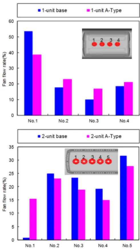
Fig. 14 Individual fan flow rate of air conditioning system
에 도시한 바와 같이 A-Type스포일러 부착시 1-unit 모델은 약 74 %, 2-unit 모델은 21 %의 풍량 증대를 야기하였고 공기저항은 각각 약 4.9 %, 5.7 % 개선되 었다.
A-Type 스포일러 유무에 따른 각 공조 팬의 기여 도를 Fig. 14에 도시하였다. 스포일러가 없는 1-unit 모델은 가장 전방에 있는 팬에서 최대 풍량이 형성 되며 각 팬별 풍량 편차가 크나 A-Type 스포일러가 부착되는 경우 이러한 풍량 편차가 감소하였다. 특 히 2-unit 모델의 경우에는 스포일러 가 없는 경우 첫 번째 팬의 기여도는 매우 적지만 스포일러 부착으 로 인해 풍량이 급격히 증대되었고 팬 유입 풍량 편 차도 감소하는 결과를 보였다.
4. 결 론
공력 및 공조 성능을 고려한 프런트 스포일러 최 적 형상을 도출하기 위하여 정밀 디지털 풍동을 활 용한 본 연구를 통해 다음과 같은 결론을 얻었다.
A Numerical Simulation of a Roof Spoiler for Aerodynamic and Air-conditioning Performance Improvement in a Large-sized Bus
1) 1/4 스케일 모델 풍동 시험과의 비교시 공기저항 은 약 2.5 % 이내의 오차를 보였으며 디지털 풍 동 해석시 실차 주행시험으로 획득하기 힘든 유 동장에 관한 상세정보를 얻을 수 있었다.
2) 디지털 풍동 해석을 통해 공조시스템 주변의 공 기 유출입 등에 대한 매우 복잡한 흐름을 가시화 하여 프런트 스포일러 장착에 따른 전반적인 유 동특성에 대한 이해를 도모할 수 있었다.
3) A-Type과 C-Type 스포일러 부착시 에어콘 상부 에서 형성되는 와류 영역이 거의 소멸되었으며 C-Type 스포일러 부착시 공기저항이 가장 크게 개선되었다.
4) 자연 외기 유입 특성은 A-Type이 가장 유리한 구 조임을 알 수 있었으며 팬 작동 조건에서 의 공기 저항은 1-unit 모델은 약 4.9 %, 2-unit 모델은 5.7 % 개선되었고 공조 풍량 또한 각각 74 %, 21 % 증 대되었다.
References
1) K. P. Garry, “Development of Container-Mounted Devices for Reducing the Aerodynamic Drag of Commercial Vehicles,” Journal of Wind Engineering and Industrial Aerodynamics, Vol.9, Nos.1-2, pp.113-124, 1981.
2) K. P. Garry and J. L. Stollery, “Reducing the Aerodynamic Drag of Commercial Vehicles,”
International Journal of Vehicle Design, Vol.3, No.2, 1982.
3) O. Baysal and I. Bayraktar, “Computational Simulations for the External Aerodynamics of Heavy Trucks,” SAE 2000-01-3501, 2000.
4) J. Barlow, R. Guterres, R. Ranzenbach and J.
Williams, “Wake Structure of Rectangular Bodies with Radiused Edges Near a Plane Surface,”
SAE 1999-01-0648, 1999.
5) J. Williams, J. Barlow and R. Ranzenbach,
“Experimental Study of CD Variation with Aspect Ratio,” SAE 1999-01-0649, 1999.
6) A. J. Przekwas, Y. Jiang and Z. Tan “Unstruc- tured Adaptive Grid Solution Methodology for
Automotive Aerodynamics,” SAE 970142, 1997.
7) K. Unida, K. Okumura and T. Kuriyama, “The Development of Practical Aerodynamic Simulations,” JSAE 958544, 1995.
8) M. Kim, J. Jeon and Y. Park, “A Numerical Simulation on the Development of a Front Spoiler in a Large-Sized Bus,” KSAE Spring Conference Proceedings, pp.1103-1110, 2012.
9) Y. Takemori, S. Kato, Y. Masumitsu, Y. Kaya and T. Mizutani, “Drag Reduction of Bluff- Based by Wake Control Vanes(Effective Utili- zation of Under Floor Flow),” FISITA World Automotive Congress, F2000G357, 2000.
10) D. Sim, S. Lee and C. Kim, “Development of Induced Drag Reduction Device(IDRD) for an Aerodynamic Drag Reduction on a Heavy-Duty Truck,” KSAE Annual Conference Proceedings, pp.1001-1006, 2014.
11) S. Perzon, J. Janson and L. Hoglin, “On Com- parison Between CFD Methods and Wind Tunnel Tests on a Bluff Body,” SAE 1999-01-0805, 1999.
12) C. Kim and S. Lee, “An Experimental Study on the Aerodynamic Characteristics of a Streamline -designed High-speed Bus,” Transactions of KSAE, Vol.24, No.2, pp.198-204, 2016.
13) A. F. Abdel Azim El-Sayed and M. M. Nassief,
“An Investigation in to the Aerodynamics of the External Flow Around a Bus,” SAE 962173, 1996.
14) C. Teixeria, Continuum Limit of Lattice Gas Fluid Dynamics, Ph. D. Dissertation, MIT, Cambridge, 1992.
15) R. Lietz, S. Mallick, S. Kandasamy and H.
Chen, “Exterior Airflow Simulations Using a Lattice Boltzman Approach,” SAE 2002-01-0596, 2002.
16) S. R. Ahmed, G. Ramm and G. Faltin, “Some Salient Features of the Time Averaged Ground Vehicle Wake,” SAE 840300, 1984.