Introduction
Maxillofacial defects as a result of the surgical resec- tion of tumors are usually reconstructed with maxillofa- cial prosthetics. The fabrication of these prostheses most commonly involves the construction of plaster study mod- els obtained using conventional impression techniques.
This is a difficult procedure not only for the patient but
also for the prosthodontist who must take accurate impres- sions of a large defect. In this regard, conventional impres- sion techniques suffer from deformation or tearing of the material when the impression is removed from the mouth and loss of impression accuracy due to nasal mucosal secretion on the impression material.1Recently, the use of virtual planning for the restoration of tissues that are lost due to trauma or tumor surgery has become popular in the field of reconstructive surgery. In addition, application of computer-aided diagnosis and computer-aided manufac- turing facilitates planning and execution, particularly in complex anatomical situations involving different layers of tissues.2
Accuracy of virtual models in the assessment of maxillary defects
Kıvanç Kamburo˘glu1,*, S¸ebnem Kurs¸un2, Cenk Kılıç3, Tuncer Özen4
1Department of Dentomaxillofacial Radiology, Faculty of Dentistry, Ankara University, Ankara, Turkey
2Division of Dentomaxillofacial Radiology, Ministry of Health, Oral and Dental Health Center, Bolu, Turkey
3Department of Anatomy, Gülhane Military Medical Academy, Ankara, Turkey
4Department of Dentomaxillofacial Radiology, Dental Science Center, Gülhane Military Medical Academy, Ankara, Turkey
ABSTRACT
Purpose: This study aimed to assess the reliability of measurements performed on three-dimensional (3D) virtual models of maxillary defects obtained using cone-beam computed tomography (CBCT) and 3D optical scanning.
Materials and Methods: Mechanical cavities simulating maxillary defects were prepared on the hard palate of nine cadavers. Images were obtained using a CBCT unit at three different fields-of-views (FOVs) and voxel sizes: 1) 60
×60 mm FOV, 0.125 mm3(FOV60); 2) 80×80 mm FOV, 0.160 mm3(FOV80); and 3) 100×100 mm FOV, 0.250 mm3(FOV100). Superimposition of the images was performed using software called VRMesh Design. Automated volume measurements were conducted, and differences between surfaces were demonstrated. Silicon impressions obtained from the defects were also scanned with a 3D optical scanner. Virtual models obtained using VRMesh Design were compared with impressions obtained by scanning silicon models. Gold standard volumes of the impression models were then compared with CBCT and 3D scanner measurements. Further, the general linear model was used, and the significance was set to p==0.05.
Results: A comparison of the results obtained by the observers and methods revealed the p values to be smaller than 0.05, suggesting that the measurement variations were caused by both methods and observers along with the different cadaver specimens used. Further, the 3D scanner measurements were closer to the gold standard measurements when compared to the CBCT measurements.
Conclusion: In the assessment of artificially created maxillary defects, the 3D scanner measurements were more accurate than the CBCT measurements. (Imaging Sci Dent 2015; 45: 23-9)
KEY WORDS: Cone-beam Computed Tomography; Radiology; Maxillofacial Prosthesis; Dimensional Measurement Accuracy
Received December 7, 2014; Revised January 12, 2015; Accepted January 18, 2015
*Correspondence to : Assoc. Prof. Kıvanç Kamburo˘glu
Department of Dentomaxillofacial Radiology, Faculty of Dentistry, Ankara University, 06500, Bes¸evler, Ankara, Turkey
Tel) 90-312-2965632, Fax) 90-312-2123954, E-mail) [email protected]
Copyright ⓒ 2015 by Korean Academy of Oral and Maxillofacial Radiology
This is an Open Access article distributed under the terms of the Creative Commons Attribution Non-Commercial License (http://creativecommons.org/licenses/by-nc/3.0) which permits unrestricted non-commercial use, distribution, and reproduction in any medium, provided the original work is properly cited.
Imaging Science in Dentistry∙pISSN 2233-7822 eISSN 2233-7830
Cone-beam computed tomography (CBCT) uses a cone- shaped X-ray beam centered on a two-dimensional (2D) sensor to scan a 180�-360�rotation around the patient’s head in order to acquire the full three-dimensional (3D) volume of data. CBCT systems offer different sensor types, fields of view (FOVs), and exposure settings. Fur- ther, CBCT allows 3D imaging of the patient’s head and stores the acquired data in a volumetric dataset without superimposition of anatomical structures and magnifica- tion.3-6The volumetric dataset from the CBCT can be visualized in different ways such as multiplanar reformat- ted (MPR) slices, panoramic reformatted images, volume- rendered images, and surface-rendered images. CBCT systems are also capable of providing radiographic rather than reflective-based imaging and may be utilized in the construction of the necessary virtual impressions; this is the first step in prosthesis reconstruction. With recent ad- vancements, it has become possible to fuse digital impres- sions from computer-aided diagnosis and manufacturing systems with a CBCT dataset. Disadvantages associated with dental CBCT include scatter radiation, limited dyna- mic range, minimal soft-tissue detail, and beam hardening artifacts caused by dental-care materials and implants.3-6
The aim of the present study was to assess the reliability and validity of measurements performed on 3D virtual models of maxillary defects obtained using CBCT with different FOVs and a 3D optical scanner by comparing them with measurements performed on actual defects created ex vivo in human cadavers. The ultimate goal of this project was to develop a reproducible, reliable, and useful clinical method to create accurate virtual models from which obturating maxillofacial prostheses could be fabricated.
Materials and Methods
Approval for the use of cadaver heads (n==9) was obtain- ed from Gülhane Military Medical Academy, Department of Anatomy (Local Ethics Committee Review Number 1491-304-12/1539-604). Mechanical cavities of various sizes and dimensions simulating localized maxillary de- fects were prepared on the palatinal aspect of the hard palate by using round and cylindrical dental burs to their full depth.
Images of the cadavers were obtained using a CMOS flat panel detector, variable FOV CBCT unit (3D Accui- tomo 170, J. Morita Mfg. Corp., Kyoto, Japan) operating at 90 kVp and 5.0 mA and having an exposure time of 17.5 s to image each specimen after defect preparation at three different FOVs and voxel sizes (nominal cubic mil- limeter resolution [mm3]: 1) 60 mm×60 mm FOV, 0.125 mm3(FOV60); 2) 80 mm×80 mm FOV, 0.160 mm3 (FOV80); and 3) 100 mm×100 mm FOV, 0.250 mm3 (FOV100).
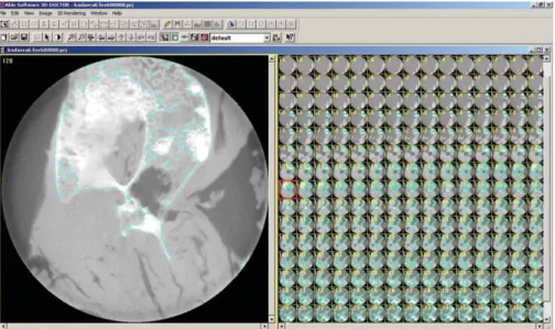
For a comparison of CBCT images taken with different FOVs, axial CBCT scans taken at each acquisition para- meter of nine defects were exported as DICOM files and then imported into volumetric rendering software capable of measurements of a vector-based segmentation techno- logy (3D Doctor, Able Software Corp., Lexington, MA, USA). This software allows defect segmentation on con- secutive axial slices, enabling defect visualization at each level. This ensured manual, detailed slice-by-slice seg- mentation of the defect borders by using a mouse with color delineation (turquoise green). The maxillary cada- ver images in which defects were identified were outlined with the mouse by using a tool called “Free” to remark at
Fig. 1. Segmentation process with 3D Doctor
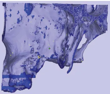
the region of interest. Figure 1 shows the segmentation process with 3D Doctor. After reconstruction with 3D Doctor, superimposition of the maxilla images obtained at different FOVs was performed by using VRMesh Design (Virtual Grid, Bellevue City, WA, USA). Then, virtual models obtained at each FOV were cut from the common intersection points in order to obtain identical borders of the maxillas. Thereafter, automated volume measurements were conducted, and differences between surfaces were demonstrated. Figure 2 shows the alignment of standard- ized FOV images, and Figure 3 shows the measurement of differences using standardized FOV images.
Silicon impressions obtained from the defects were also scanned with a Smart Optics Activity 880 3D Dental Scan- ner (Smart Optics, Bochum, Germany). Virtual models obtained using VRMesh Design were compared with impressions obtained by scanning silicon models. Virtual models obtained from nine maxillary defects are shown in Figure 4.
In addition, a non-deformable light flow silicon impres- sion material (Variotime; Heraeus-Kulzer, Hanau, Ger- many) was injected into the defects, and the volumes of the impression models were measured by using the “water displacement technique.” This technique can be mathe- matically expressed as follows: Lost volume of the water in the cylinder- initial volume of the water in the cylin- der==defect volume. Volumetric measurements of the impression models were taken twice with a 1-week inter- val using a Scaltec SBC 21 balance (Denver Instrument, Bohemia, NY, USA) by an external independent research- er (physiologist). The average volume was considered the
reference standard. All physical measurements were then compared with the CBCT and 3D optical scanner mea- surements.
All measurements were performed twice by two obser- vers, and an average was compared to the physical volume calculated from the impression material. The images were viewed in a dimly lit room on a 15.6-in laptop monitor (F75 5-3D350, Qosmio, Toshiba, Tokyo, Japan) at a screen resolution of 1920×1080 and color depth of 32 bits.
Each examiner was trained until he/she felt comfortable with the use of the software tools. The gold standard results were used to validate the accuracy of the CBCT and 3D optic scanner readings in the assessment of the
Fig. 2.Alignment of standardized field of view (FOV) images
Fig. 3. Measurement of differences using standardized FOV images
Fig. 4.Virtual models obtained from nine maxillary defects
defect volume and to compare any difference between these findings. Further, the general linear model was used as the statistical analysis method, and the significance was set to p==0.05.
Results
A comparison of FOVs according to observers revealed that the p values were smaller than 0.05 (p==0.009) for different FOVs and observers. However, this variation in the measurements was mainly attributed to the different cadaver specimens used. Comparisons of different FOVs on the basis of observers are presented in Table 1 and
Figure 5. There was a significant difference between both observers, but among the total variation of FOV values, this difference contributed to a clinically small percen- tage. The variation among observers for different FOVs ranged between 0 and 10000 mm3with an average of 994 mm3, which could be considered clinically insignificant.
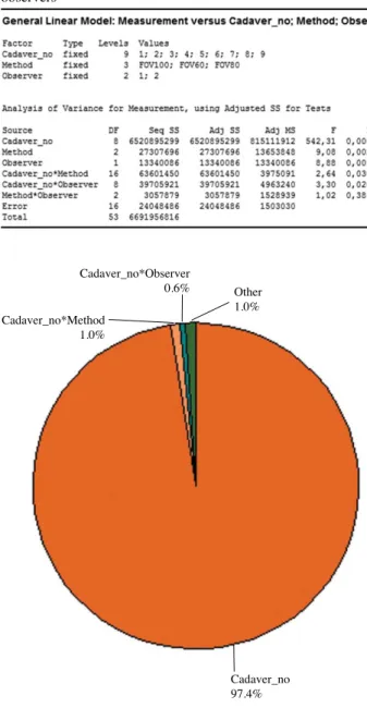
Only CBCT (FOV60) images were used for the compar- ison of CBCT and 3D optical scanner methods according to the observers and the gold standard. A comparison of the results obtained by the observers and the methods used in this study revealed that the p values were smaller than 0.05, suggesting that the measurement variations were caused by both methods and observers along with
Table 2. Comparison of cone-beam computed tomography and 3D scanner methods on the basis of observers and gold standard Table 1.Comparisons of different field-of-views on the basis of
observers
Fig. 5.Comparisons of different FOVs on the basis of observers
Fig. 6. Comparison of cone-beam computed tomography and three-dimensional scanner methods on the basis of observers and the gold standard
Cadaver_no*Observer 0.6%
Cadaver_no 97.4%
Other 1.0%
Cadaver_no*Method 1.0%
Cadaver_no*Method Observer 3.4%
0.3%
Method 3.2%
Others 0.8%
Cadaver_no 92.4%
the different cadaver specimens used. The comparison of CBCT and 3D optical scanner methods on the basis of the observers and the gold standard is presented in Table 2 and Figure 6.
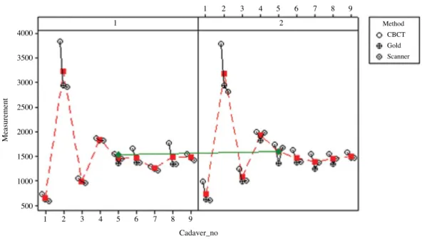
For both observers, 3D scanner measurements were closer to the gold standard measurements compared to the CBCT measurements. The multi-vari chart for measure- ment by method/observer is shown in Figure 7.
Discussion
3D computed tomography (CT) models of jaw defects have the potential to play a significant role in prosthodon- tics and are a relatively new trend in dentistry. Optical scanners that form 3D computer models have been veri- fied to enable sufficient system accuracy for clinical pra- ctice.7Boldt et al.8generated models of an edentulous max- illa by photo-optical, laser-optical, CT-based, and tactile means and compared the various findings to a reference plaster cast. Barone et al.9stated that the accuracy and res- olution of the optical scanner as compared to CBCT scan- ning allows optimal reconstructions of both tooth crown surfaces and oral soft tissues.
Several studies on the accuracy of intraoral scanners and digital impressions have been published, reporting single- unit restorations, several teeth in a row, quadrants, and full arch scans.1Motohashi and Kuroda10developed a 3D computer-aided system and scanned dental study models with a slit-ray laser beam, and Lu et al.11introduced a laser
scanning 3D digitization system for dental casts by using a special semiconductor laser. Hirogaki et al.12 scanned dental casts by using a line laser scanner and compared the measurements taken on computer-reconstructed mod- els with those taken on actual casts. The difference was within 0.3 mm, which was in accordance with our results.
Several quantitative studies have been carried out on the use of CBCT systems and software in dental volumet- ric analysis. A study compared volumes of the extraction sockets by using software-guided segmentation estimated from CBCT images with the values obtained using Archi- medes’ principle; this previous study reported a good match between results similar to ours.13
The clinical use of 3D surface models obtained from CBCT includes pre-operative implant planning, assess- ment of the jaws, evaluation of the bone volume required for orthognathic surgery, and generation of physical den- tal models of the jaws by using stereolithography techno- logy.14,15 The accuracy of a digitized model is restricted by the accuracy of the dental impression and cast, which could be variable and incoherent over time based on sev- eral factors. In practice, several patient scanning and data reconstruction parameters influence the subjective CBCT image quality. All these factors may also influence the quality of the 3D surface models reconstructed from CBCT images.16,17
The variation in the threshold value was less in the man- dible than in the maxilla. This can be explained by the fact that the cortical bone in the mandible is sufficiently
Fig. 7.Multi-vari chart for measurement by method/observer
1 2 3 4 5 6 7 8 9
1 2 3 4 5 6 7 8 9
4000 3500 3000 2500 2000 1500 1000 500
Measurement
Cadaver_no
1 2
Panel variable: Observer
Method CBCT Gold Scanner
thick to keep the attenuation profile uniform across the entire bone surface, while in the maxilla, the varied thin cortical bone, particularly in the palate and tuberosity re- gions, creates the effect of bone dehiscence and fenestra- tion artifacts in the 3D model.18
Other reports showing the use of CBCT for estimating the volume of teeth, pulp chamber, mandibular condyle, and upper airway volume also exist.19 In studies analyz- ing the effect of section thickness on volume estimations of organs or cavities by using CT images, the authors reported underestimations of the volumes, which were caused by increases in the slice thickness.20,21
The accuracy of segmentation relies on the gray value and the threshold value entered by the operator. Unfortu- nately, CBCT scanners do not have calibrated Hounsfield unit values. This implies that the gray values can differ for each scanner. In some previous studies, researchers used a threshold set automatically and independent of the operator.18,22However, another study found the automated segmentation to have a greater error in assessing the vol- ume of the lesions than manual readings (2% and 0.4%, respectively).23 Ahlowalia et al.24 compared the efficacy of micro-CT and CBCT on the measurement of bone def- ect volumes. Their results indicated that both CBCT and micro-CT showed a high degree of agreement when com- pared to the “Archimedes’ principle” measurements.
Weissheimer et al.25 compared six different imaging software programs, namely Mimics, Dolphin3D, ITK- Snap, OsiriX, InVivo Dental, and Ondemand3D, for mea- suring the upper airway volume. All six imaging soft- ware programs were reliable but had errors in the volume segmentations of the oropharynx. Mimics, Dolphin3D, ITK-Snap, and OsiriX were similar (showed less than 2%
errors) and more accurate than InVivo Dental and Onde- mand3D (showed more than 5% errors) for the upper air- way assessment.25In the present study, we preferred the use of 3D Doctor and VRMesh Design since both of them were appropriate for our study design. According to com- pany information, 3D Doctor uses a unique vector-based technology for better 3D mesh model creation and easy editing. In addition, the surface model uses a relatively small number of triangles while maintaining all details for high-quality rapid-prototyping applications. On the other hand, VRMesh Design offers the advantages of automatic point cloud classification, advanced point cloud decimation and denoising, accurate point cloud triangu- lation, and advanced stereolithography (STL) file repair and editing.
In conclusion, in the assessment of artificially created
maxillary defects, we found clinically insignificant differ- ences between observers and CBCT FOVs; however, 3D optical scanner measurements were more accurate than the CBCT measurements. Our findings might be useful for developing a reproducible, reliable, and useful clinical method to create accurate virtual models for the fabrica- tion of obturating reconstructive prostheses.
Acknowledgments
We would like to express our sincere gratitude to Ayberk Yagiz of Ay Tasarim, Ankara, Turkey, for his assistance with this study.
References
1. Yuzbasıoglu E, Kurt H, Turunc R, Bilir H. Comparison of digital and conventional impression techniques: evaluation of patients’ perception, treatment comfort, effectiveness and clinical outcomes. BMC Oral Health 2014; 14: 10.
2. Lethaus B, Kessler P, Boeckman R, Poort LJ, Tolba R.
Reconstruction of a maxillary defect with a fibula graft and titanium mesh using CAD/CAM techniques. Head Face Med 2010; 6: 16.
3. Angelopoulos C, Scarfe WC, Farman AG. A comparison of maxillofacial CBCT and medical CT. Atlas Oral Maxillofac Surg Clin North Am 2012; 20: 1-17.
4. Scarfe WC, Farman AG, Levin MD, Gane D. Essentials of maxillofacial cone beam computed tomography. Alpha Ome- gan 2010; 103: 62-7.
5. Scarfe WC, Farman AG. What is cone-beam CT and how does it work? Dent Clin North Am 2008; 52: 707-30.
6. Scarfe WC, Li Z, Aboelmaaty W, Scott SA, Farman AG.
Maxillofacial cone beam computed tomography: essence, ele- ments and steps to interpretation. Aust Dent J 2012; 57 Suppl 1: 46-60.
7. Kamegawa M, Nakamura M, Fukui Y, Tsutsumi S, Hojo M.
Direct 3-D morphological measurements of silicone rubber impression using micro-focus X-ray CT. Dent Mater J 2010;
29: 68-74.
8. Boldt F, Weinzierl C, Hertrich K, Hirschfelder U. Compari- son of the spatial landmark scatter of various 3D digitaliza- tion methods. J Orofac Orthop 2009; 70: 247-63.
9. Barone S, Paoli A, Razionale AV. Creation of 3D multi-body orthodontic models by using independent imaging sensors.
Sensors (Basel) 2013; 13: 2033-50.
10. Motohashi N, Kuroda T. A 3D computer-aided design system applied to diagnosis and treatment planning in orthodontics and orthognathic surgery. Eur J Orthod 1999; 21: 263-74.
11. Lu P, Li Z, Wang Y, Chen J, Zhao J. The research and devel- opment of noncontact 3-D laser dental model measuring and analyzing system. Chin J Dent Res 2000; 3: 7-14.
12. Hirogaki Y, Sohmura T, Satoh H, Takahashi J, Takada K.
Complete 3-D reconstruction of dental cast shape using per- ceptual grouping. IEEE Trans Med Imaging 2001; 20: 1093-
101.
13. Agbaje JO, Jacobs R, Michiels K, Abu-Ta’a M, van Steen- berghe D. Bone healing after dental extractions in irradiated patients: a pilot study on a novel technique for volume assess- ment of healing tooth sockets. Clin Oral Investig 2009; 13:
257-61.
14. Turbush SK, Turkyilmaz I. Accuracy of three different types of stereolithographic surgical guide in implant placement: an in vitro study. J Prosthet Dent 2012; 108: 181-8.
15. Pohlenz P, Blessmann M, Blake F, Gbara A, Schmelzle R, Heiland M. Major mandibular surgical procedures as an indi- cation for intraoperative imaging. J Oral Maxillofac Surg 2008; 66: 324-9.
16. Katsumata A, Hırukawa A, Okumura S, Naitoh M, Fujishita M, Ariji E, et al. Effects of image artifacts on gray-value den- sity in limited-volume cone-beam computerized tomography.
Oral Surg Oral Med Oral Pathol Oral Radiol Endod 2007;
104: 829-36.
17. Kwong JC, Palomo JM, Landers MA, Figueroa A, Hans MG.
Image quality produced by different cone-beam computed tomography settings. Am J Orthod Dentofacial Orthop 2008;
133: 317-27.
18. Hassan B, Couto Souza P, Jacobs R, de Azambuja Berti S, van der Stelt P. Influence of scanning and reconstruction para- meters on quality of three-dimensional surface models of the dental arches from cone beam computed tomography. Clin Oral Investig 2010; 14: 303-10.
19. Sezgin OS, Kayıpmaz S, Sahin B. The effect of slice thickness on the assessment of bone defect volumes by the Cavalieri principle using cone beam computed tomography. J Digit Ima- ging 2013; 26: 115-8.
20. Emirzeoglu M, Sahin B, Selcuk MB, Kaplan S. The effects of section thickness on the estimation of liver volume by the Cavalieri principle using computed tomography images. Eur J Radiol 2005; 56: 391-7.
21. Sahin B, Mazonakis M, Akan H, Kaplan S, Bek Y. Depen- dence of computed tomography volume measurements upon section thickness: an application to human dry skulls. Clin Anat 2008; 21: 479-85.
22. Loubele M, Maes F, Schutyser F, Marchal G, Jacobs R, Sue- tens P. Assessment of bone segmentation quality of cone- beam CT versus multislice spiral CT: a pilot study. Oral Surg Oral Med Oral Pathol Oral Radiol Endod 2006; 102: 225-34.
23. Pinsky HM, Dyda S, Pinsky RW, Misch KA, Sarment DP.
Accuracy of three-dimensional measurements using cone- beam CT. Dentomaxillofac Radiol 2006; 35: 410-6.
24. Ahlowalia MS, Patel S, Anwar HM, Cama G, Austin RS, Wilson R, et al. Accuracy of CBCT for volumetric measure- ment of simulated periapical lesions. Int Endod J 2013; 46:
538-46.
25. Weissheimer A, Menezes LM, Sameshima GT, Enciso R, Pham J, Grauer D. Imaging software accuracy for 3-dimen- sional analysis of the upper airway. Am J Orthod Dentofacial Orthop 2012; 142: 801-13.