1. INTRODUCTION
The Global Positioning System (GPS), developed by the U.S. from the 1960s, is the first Global Navigation Satellite System (GNSS) to provide position, velocity and time services to global users. GPS was originally developed for military purposes, but with the release of selective availability in 2005, it is now available for civil services as well. Around the same time, Russia also developed its own GNSS, so- called GLONASS, as a counter part of the U.S. GPS, that was followed by the Galileo system of the European Union. In
ABSTRACT
This paper presents the development of an end-to-end numerical simulator for signal design of the next generation global navigation satellite system (GNSS). The GNSS services are an essential element of modern human life, becoming a core part of national infra-structure. Several countries are developing or modernizing their own positioning and timing system as their demand, and South Korea is also planning to develop a Korean Positioning System (KPS) based on its own technology, with the aim of operation in 2034. The developed simulator consists of three main units such as a signal generator, a channel unit, and a receiver. The signal generator is constructed based on the actual navigation satellite payload model. For channels, a simple Gaussian channel and land mobile satellite (LMS) multipath channel environments are implemented. A software receiver approach based on a commercial GNSS receiver model is employed. Through the simulator proposed in this paper, it is possible to simulate the entire transceiver chain process from signal generation to receiver processing including channel effect. Finally, numerical simulation results for a simple example scenario is analyzed. The use of the numerical signal simulator in this paper will be ideally suited to design a new navigation signal for the upcoming KPS by reducing the research and development efforts, tremendously.
Keywords: signal design, numerical simulator, Korea positioning system, GNSS
case of China, the following three phases of strategy were planned for the development of their satellite navigation system. Phase-1 was for an experimental system called Beidou demonstration navigation system, which was later extended to a regional satellite navigation system (RNSS) to cover China and neighboring countries in Phase-2. In Phase-3, the service target of the Beidou Navigation Satellite System (BDS) was expanded across the global and the development is currently underway with the goal of full operational capability in 2020 (Han et al. 2011). Japan has developed their own RNSS, Quasi-Zenith Satellite System, for some Asia-Pacifies countries to improve navigation performance in particular for urban region in Japan. India also operates Navigation with Indian Constellation for Indian territory as well as a region extending 1,500 km around it.
In this trend, South Korea is also planning to develop their own satellite navigation system, so-called Korea Positioning System (KPS), by 2034 (GPS World Staff 2018).
Received Nov 17, 2019 Revised Dec 07, 2019 Accepted Dec 10, 2019
†
Corresponding Author E-mail: [email protected]
Tel: +82-32-860-7406 Fax: +82-32-863-5822
Heon Shin https://orcid.org/0000-0002-5167-7551
Kahee Han https://orcid.org/0000-0001-8804-5120
Jong-Hoon Won https://orcid.org/0000-0001-5258-574X
The design of navigation signals is one of the most important issues in terms of the system’s performance, since the navigation systems currently in operation or to be developed are radionavigation satellite systems, which are based on space-to-earth wireless communication.
In particular, the issue of radio frequency compatibility becomes increasingly important because various positioning systems in different countries must fulfill the requirement on the sharing of limited frequency bands without interference.
Navigation signal design is also closely related to the user’s receiver specifications. For example, if signals from all systems are designed to have different carrier frequencies, the receivers will have very wide bandwidth to use signals from each system, therefore the cost of receiver will increase.
In this regard, the issue of interoperability that requires the design of signals so that multiple systems can be used at the same time is also an important aspect.
In the design process of new navigation signals developed after the legacy navigation systems such as GPS and GLONASS, many prior researches on the above issues were actively studied. For example, conventional GPS signals are BPSK modulated signals of which power is concentrated at the center frequency, Binary Offset Carrier (BOC) modulation techniques to separate the power spectrum of the signal from the center frequency were extensively studied and employed in many new signals (Betz 2001). To design new signals for Galileo system, various candidate signals were studied in terms of RF compatibility by spectrum separation analysis taking into account various figure-of-merits (FoMs) including autocorrelation, tracking performance, multipath error, and so on (Betz & Goldstein 2002). By the GPS-Galileo working group on interoperability and compatibility, the new modulation scheme, Multiplexed Binary Offset Carrier (MBOC), was developed and employed for GPS L1C and Galileo E1OS (Hein et al. 2006).
As the L band becomes increasingly saturated due to the congestion of the legacy and new satellite navigation system signals, several studies to design new navigation signals in other bands such as C- and S-bands have been performed.
The frequency band ranging from 5010 to 5030 MHz in C-band was allocated as the new band for radionavigation satellite system by WRC-2000. For example, a study on future GNSS systems was performed with an extensive trade-off analysis on the C-band satellite navigation (Avila-Rodriguez et al. 2007). There were studies on the utilization of S-band between 2483.5 and 2500 MHz, which is already allocated to the radiodetermination satellite system (Mateu et al. 2009).
Also analysis on the overall performance of S-band satellite system was studied in terms of signals, receivers, and payload design (Soualle et al. 2011). A number of next-generation
modulation techniques to reduce the out-of-band emission of the signal power spectrum that is inevitably occurred due to the use of rectangular chip pulses-based modulation techniques in legacy signals were studied and the relevant receiver performance was analyzed (Won et al. 2011).
In case of China, the signal performance was analyzed by comparing the spectrum of measured signals transmitted from the experimental satellite of BDS-1 with theoretical calculated spectrum (Grelier et al. 2007). Like the Galileo signals, Quadrature Multiplexed BOC modulation technology was employed as the next-generation modulation scheme for BDS-3 signals from an interoperability perspective (Yao et al.
2010). BDS-3 signals were also analyzed for the performance of the actual signal by measuring the signals transmitted from the BDS-3 experimental satellite (Zhang et al. 2017).
Recently, a research has been conducted to test the feasibility of new modulation techniques such as ACE-BOC and CEMIC modulation (Lu et al. 2019).
As aforementioned researches, when developing a new satellite navigation system, navigation signals should be designed in details for intended purposes in step by step.
This is in general done by testing various signal performances from signal generator to receiver through channel for many signal candidates. If we can analyze the performance of new signals through simulations at the laboratory level even before an experimental satellite is operational, we will be able to obtain the optimal signal design with less effort. In this regard, a prior study was conducted on the development of simulator tools for signal design (Shin et al. 2019). In this paper, the final implementation result of a numerical end-to- end signal design simulator is presented.
This paper is composed as follows. Section 2 describes the overall architecture of the simulator and each element such as signal generator, channel and receiver. In Section 3, we set up a simple example scenario and analyze the results of simulator. Finally, in Section 4, conclusions are drawn based on numerical simulation results.
2. SIMULATOR STRUCTURE
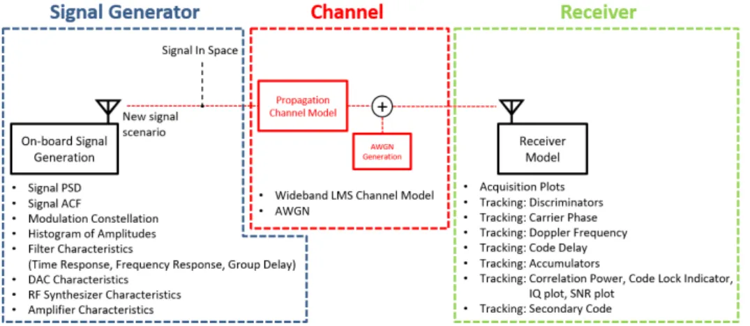
A numerical signal design simulator (NSDS) is an end-
to-end simulator consisting of three parts: signal generator,
channel, and receiver. Fig. 1 shows the overall structure
of simulator and the computed FoMs. Note that the main
purpose of NSDS is to assist the GNSS signal design. Thus,
the end-to-end sigmulator described in this paper is a single
channel simulator, not a multiple channel signal generator
widely used in receiver design.
2.1 Signal Generator
A signal generator generates the navigation signal numerically and calculates the FoMs of the generated signal.
To generate a signal preferably similar to the actual GNSS signal, the structure of the signal generator module in the NSDS should follow the signal generation chain of the payload of GNSS satellites (Rebeyrol 2007). The signal generator consists of five units such as clock unit, navigation signal generation unit, frequency generation and modulation unit, amplifier unit and output multiplexer unit as shown in Fig. 2.
The clock unit is composed of an atomic clock and Clock Management and Control Unit (CMCU). The CMCU generates a master timing reference typically having a frequency of 10.23 MHz, which generally used for GNSS.
Since it is practically difficult to implement a real atomic clock with high accuracy in a software-based simulator, the simulator implemented in this paper only considers the phase noise of atomic clock. As shown in Fig. 3, phase noise can be expressed as the power spectral density of noise with frequency offset and the stability requirements for output at 10.23 MHz of the Galileo satellite CMCU are taken into account (Carrillo et al. 2005).
The Navigation Signal Generation Unit is composed of modulators and filters to generate the navigation signal. The modulator generates a baseband signal and then converts it to an Intermediate Frequency (IF) signal in order to avoid aging of the analog mixer. Also, a base-band filter is applied right before the conversion to the IF signal to filter out the noise effect in the two services independently. Both Fig. 1. Overall structure and the relevant FoMs of numerical signal design simulator.
Fig. 2. Signal generator structure.
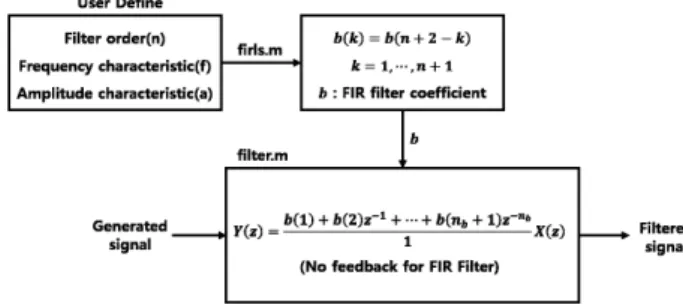
IF signals of individual services are multiplexed by linear addition scheme. The pre-distortion filter is performing to avoid spectrum mixing, reducing out-of-band emissions and compensate for Digital-to-Analog Converter (DAC) shaping or any other distortion brought by the following analog processing. In the simulator proposed in this paper, several filters, including pre-distortion digital filters, are implemented as minimum square linear phase FIR filters using Matlab built-in functions. The implementation process of the filter is shown in Fig. 4.
Frequency Generation and Modulation Unit (FGMU) consists of frequency synthesizers, DAC, mixer, filter and so on.
An analog filter is commonly used in the actual payload to limit out-of-band emissions and prevent spectral distortion due to DAC and spectral re-combinations that may occur after up- converter. The FGMU modulates the signal to be transmitted into a carrier frequency band. However, since it is difficult to process the high frequency signal in the time domain in the simulation, only the effect due to the phase noise occurring in the RF synthesizer is considered in this paper.
The Amplifier Unit amplifies the signal and then transmits the GNSS signal to the ground. The characteristics of the amplifier can be expressed by the amplitude response and the phase response. Due to the nonlinear characteristic of the amplifier, the GNSS signal must generally satisfy constant envelope. Output Multiplex is a filter that reduces sidelobes at the end of the signal transmitter of the payload.
The Signal generator module calculates the FoMs of the signals during the generation. The FoMs relevant to the signal generator used in this paper are as follows. Signal Power Spectral Density (PSD), Signal Auto-Correlation Function (ACF), modulation constellation, histogram of amplitudes, filter characteristics, DAC characteristics, RF synthesizer characteristics, and amplifier characteristics.
2.2 Channel
The effect of the communication channel consists of the Additive White Gaussian Noise (AWGN) and fading by the user’s
dynamics and signal multipath. In a variety of communication channels, including wired and wireless channels, the motion of electrons by thermal energy results in additional noise and can be modelled as a Gaussian distribution. Ideal AWGN has all frequency components, but because the actual receiver has limited bandwidth, noise has finite power.
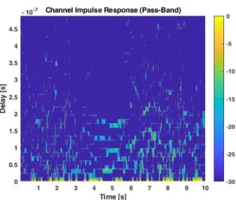
The simulator proposed in this paper used the land mobile satellite (LMS) multipath channel model provided by German aerospace center (DLR) to implement the multipath channel environment. In 2002, the DLR performed a measurement project for the assessment of the Satellite Navigation Land Mobile Multipath Channel (Steingass & Lehner 2004). Based upon the obtained measurement data, a channel model was developed and DLR provides Matlab function for research purposes for free (Steingass & Lehner 2005).
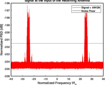
A multipath channel model considering several user dynamics such as pedestrian and cars is incorporated in channel. The ideal AWGN channel is also implemented simply by using Matlab functions. FoMs of channel are as follows. power delay profile – Probability Density Function, channel impulse response (passband), velocity, heading, signal PSD, signal at the input of the receiving Antenna.
2.3 Receiver
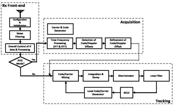
The receiver has been implemented by RF front-end, acquisition and tracking. Fig. 5 shows the overall receiver architecture and its data flow from generated IF signals to final FoMs as output (Misra & Enge 2006).
The generated IF signals input from the generator are filtered by an RF noise reduction filter and then down converted into lower IF signals. A lowpass filter is used to remove high frequency signals that may be generated from down mixing procedure. Here, fundamental processing block size is set to be the number of samples with respect to pre- detection integration time (PIT). Acquisition and/or tracking functions are activated in every PIT iteratively depending on the estimates of signal-to-noise ratio (SNR).
The acquisition usually operates once only after the
Fig. 3. Phase noise of CMCU. Fig. 4. Filter implementation.
start of receiver operation to obtain coarse estimates of signal parameters of interest. After then, the tracking loop continuously performs to get fine estimates of signal parameters of interest until the end of receiver operation.
When the receiver enters the re-acquisition stage if the obtained SNR is not sufficient due to failure of tracking. At the re-acquisition procedure, the receiver tries to re-acquire the signal by increase the PIT, for example, up to 20 times longer in case of GPS L1 C/A. Then, it stops all signal procedures if the receiver fails to re-acquire the signal in presence. In final stage of receiver module, FoMs of receiver are calculated and then stored in order to display all of receiver FoMs. Receiver FoMs selected in this paper are as follows: acquisition search- plot with respect to code and Doppler offset, discriminator outputs in tracking loops, Doppler and delta-Doppler, tracking estimates of code and carrier phases, accumulation outputs, code powers and lock indicators with respect to code and carrier, in-phase/quadrature (I/Q) plot, SNR and carrier- to-noise ratio (C/N0), secondary code tracking results.
3. SIMULATION RESULT
Based on the simulator structure presented in Section 2, the NSDS is implemented and its performance is verified through an example scenario.
3.1 Scenario Configuration
Table 1 represents the major simulation parameters set
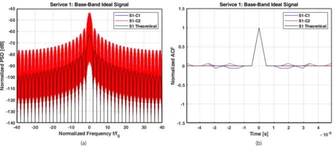
for an example scenario in signal generator, channel and receiver. Service 1 signal is modulated by Quadrature Phase Shift Keying (QPSK) modulation, and service 2 signal is modulated by BOC(1,1) modulation. Each signal has I/Q phase, where in-phase is for component 1, and quadrature is for component 2. In this example, component 1 is used as the data channel and component 2 was used as the pilot channel.
The channel is basically an AWGN channel and depending on the setup, the LMS multipath channel with user dynamics can be applied as shown in the table.
Fig. 5. Receiver structure.
Table 1. Simulation parameter for example scenario
Part Scenario setting parameter Service 1 Service 2