installation of mini-implants
Soobin Shin, Pan-Soo Park, Seung-Hak Baek, Il-Hyung Yang*
Department of Orthodontics and Dental Research Institute, Seoul National University School of Dentistry, Seoul, Korea
Research Article
J Periodontal Implant Sci 2015;45:62-68 http://dx.doi.org/10.5051/jpis.2015.45.2.62
Purpose: The goal of this study was to investigate the histomorphometric characteristics of the healing process of microcracks in the cortical bone after the installation of mini-im- plants (MIs).
Methods: Self-drilling MIs were inserted into the tibial diaphysis of twelve adult male New Zealand rabbits. Four MIs per rabbit were placed randomly. The animals were divided into four groups according to the length of the healing period: group A was sacrificed immedi- ately, group B was sacrificed after one week, group C was sacrificed after two weeks, and group D was sacrificed after four weeks. Cortical bone thickness was measured using mi- cro-computed tomography, and histomorphometric analyses of the cumulative length of the microcracks (CLCr) and the total number of microcracks (NCr) were performed using hematoxylin and eosin staining.
Results: The microcracks were radially and concentrically aligned in the peri-MI bone. The CLCr decreased significantly one week after the surgery, mainly due to healing of the con- centrically aligned microcracks. The CLCr showed another significant decrease from two weeks after the surgery to four weeks after the surgery, mainly reflecting healing of the ra- dially aligned microcracks. A statistically significant decrease in the NCr occurred as the microcracks healed from zero weeks to two weeks. However, no significant difference in the NCr was found between groups C and D.
Conclusions: In order to improve the primary stability of MIs, delayed loading and a heal- ing period of a certain length are recommended to ensure the optimal healing of micro- cracks and bone remodeling.
Keywords: Bone remodeling, Orthodontic anchorage procedures.
Received: Mar. 18, 2015 Accepted: Apr. 19, 2015
*Correspondence:
Il-Hyung Yang
Department of Orthodontics and Dental Research Institute, Seoul National University School of Dentistry, 101 Daehak-ro, Jongno-gu, Seoul 110-749, Korea
E-mail: drortho@snu.ac.kr Tel: +82-2-2072-4701 Fax: +82-2-2072-3817
INTRODUCTION
Anchorage is the source of resistance to the forces that are generated in reaction to the active component of an appliance, and it plays a very important role in orthodontic treat- ment [1]. Recently, various skeletal anchorage systems including endosseous implants, mini- implants, and mini-plates have entered into clinical use. Among them, mini-implants (MIs, also known as temporary anchorage devices) are most frequently used due to their ease of installation [2].
The successful installation of MIs is influenced by the skeletal pattern of the patient, im- mediate or late loading, oral hygiene, and the shape of the MI [3,4], and success rates rang- ing from 84% to over 90% have been reported in several studies [5,6]. While MIs are very
This is an Open Access article distributed under the terms of the Creative Commons Attribution Non-Commercial License (http://creativecommons.org/licenses/by-nc/3.0/).
similar to dental implants, they are different in that some MIs do not exhibit osseointegration with the surrounding bone. Therefore, the primary stability of an MI, also known as its initial stability, is more important for the successful installation of MIs than it is for the installation of dental implants.
The primary stability of an MI is achieved by mechanical coher- ence between the bone and the MI immediately after installation, while secondary stability is achieved after healing, by means of a process in which osteoblasts form fibrous and lamellar bone around the inserted MI. The factors affecting primary stability are bone density, surgical technique, and the morphology of the MI [7-10], which have also been studied in the context of dental implants [11- 13]. After a certain period of healing, secondary stability plays a more important role. The transition process between primary and secondary stability is critical, because anchorage stability depends on the completion of bone remodeling. Studies investigating prima- ry stability have mainly dealt with macroscopic and clinical factors;
however, little is known about the relationship between macroscop- ic factors and histologic reactions. There are a limited number of studies which have suggested that microcracks and microdamage are the factors affecting the primary stability of MIs [10,14] Fur- thermore, microcracks play an important role in bone physiology because they induce remodeling of the cortical bone [15-17]. There- fore, the quantification of microcracks, along with bone mass mea- surements, has been suggested to be a useful technique in then ex- perimentally estimation of the degree of bone remodeling [18].
A relationship between the diameter of an MI and the emergence of microcracks after installation has been reported in previous stud- ies, although no consensus has been reached. Other studies have demonstrated different dynamics of microcrack generation in a range of installation methods including self-drilling, self-tapping, and pilot drilling installation [19,20].
Although MIs are widely used, the effect of microcracks on pri- mary stability is still insufficiently studied. Moreover, to the best of our knowledge, no studies have investigated how microcracks gen- erated during the installation procedure heal. The purpose of this study was to investigate the histomorphometric characteristics of the healing process of microcracks in the cortical bone after the in- stallation of MIs.
MATERIALS AND METHODS
Twelve mature New Zealand white rabbits (males; mean age, six months; mean weight, 3.1 kg) were used according to a protocol that was approved by the Animal Ethics Committee of Seoul Na- tional University (SNU-100831-1).
Cylindrically shaped self-drilling MIs (titanium-aluminum-vana- dium alloy; Biomaterials Korea, Seoul, Korea), 1.5 mm in diameter and 6 mm in length, were used (total number of MIs=48). In order to exclude the possible effect of extraneous factors on microcrack formation, the design, diameter, and length of the MIs were iden- tical and a single company was used.
All rabbits were randomly assigned to one of four groups, using a round-robin method [21]: the immediate sacrifice group, the one-week healing group, the two-week healing group, and the four-week healing group. Four MIs were placed in the tibia of each rabbit.
The rabbits were anesthetized and an operation field was pre- pared on the medial side of the upper portion of the hind leg by shaving the fur and disinfecting the area with povidone iodine. Lo- cal anesthesia was performed with 2% lidocaine hydrochloride and 1:100,000 epinephrine (Gwangmyung, Seoul, Korea). After a full- thickness stab incision was made on the target site in the proximal third of the tibia, an MI was placed on the site via a surgical device (Elcomed SA-200C, W&H Dentalwerk, Bürmoos, Austria). The inser- tion settings involved a maximum torque of 30 cN and 20 rpm. Two MIs were placed on each side, with a minimum distance of 2 cm between them. After the operation, all rabbits were administered antibiotics and anti-inflammatory medication. The rabbits were sacrificed at zero days (group A), one week (group B), two weeks (group C), and four weeks (group D) after surgery. Two 2-cm long bone segments containing the MIs were cut from each tibia. Each specimen contained one MI in the central region. However, two rabbits were lost during the healing period and three specimens were abandoned during the harvesting procedure because of spon- taneous fracture. In order to prevent additional microcracks during the removal of the MI, specimens were prepared with the MIs in situ. Subsequently, the cortical bone thickness adjacent to the MI was measured using micro-computed tomography (1072 X-ray mi- crotomography, Skyscan, Antwerp, Belgium) and a computed to- mography analyzer (version 16.1, Skyscan, Antwerp, Belgium). The bone density of each specimen, expressed in Hounsfield units, was examined to see whether it was between 1,200 and 1,600 [22], which is known to be the normal human range; rabbits have similar cortical bone density values to humans [23].
The blocks were fixed with 4% paraformaldehyde for three weeks, dehydrated with gradient alcohol (90%, 90%, 95%, and 100% alco- hol for one day each) and embedded in Kleer set resin TM (Metprep Ltd., Coventry, UK). They were then sliced. The specimens were ground perpendicular to the MI to a thickness of 40–50 μm using the EXAKT cutting and grinding system (EXAKT Apparatebau, Norderstedt, Ham- burg, Germany) and stained with hematoxylin and eosin (H&E). Ten consecutive sections were prepared for each specimen and the mid- dle two sections were selected for observation.
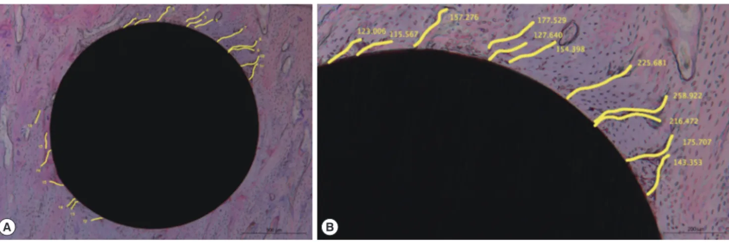
Histomorphologic and histomorphometric observations were performed using a microscope and Image J software (version 1.49a, National Institutes of Health, Bethesda, Maryland, USA). The total number of cracks (NCr, reflecting the number of cracks at least 50 μm long) and the cumulative length of the cracks (CLCr) were mea- sured using a protocol described in a previous study [10] (Fig. 1).
Differences in mean values among the four groups were com- pared using the Kruskal-Wallis test and the Mann-Whitney U test with the Bonferroni correction, in order to investigate changes in the microcracks depending on the length of healing.
RESULTS
Histomorphologic analysis
As visualized by H&E staining, microcracks were radially or con- centrically aligned in the peri-MI bone area. Microdamage was mainly seen in two opposite sides that formed an axis, and was rare- ly found in the other two areas perpendicular to that axis. Although it was not reliably distinguishable, diffuse damage appeared to be found in the peri-MI bone and linear microcracks seemed to propa- gate from the surface of the MI. The linear microcracks had various lengths, and some of them even originated at some distance from the surface of the MI. Many ruptured osteocyte lacunae could be found adjacent to the MI (Fig. 2).
Although no distinguishable difference was found between groups B and C, long linear microcracks were found to disappear as the healing process continued from zero to four weeks after the sur- gery. When groups A and B were compared, concentrically aligned microcracks were found to have undergone a significant decrease prior to the radially aligned microcracks. A decrease in the radially aligned microcracks was noted in groups C and D, in comparison with groups A and B. It was also noted that microcracks starting from the surface of the MI was more hardly found in group D than in group A (Fig. 2).
Histomorphometric analysis
All specimens showed values of bone density within the normal range, between 1,200 and 1,600 Hounsfield units (data not shown).
No significant differences were found in the thickness of the corti- cal bone among the four groups (Table 1).
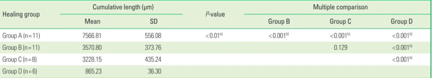
The CLCr tended to decrease as the healing time increased, al- though a statistically significant difference was not found between groups B and C (P=0.129). However, statistically significant de- creases in the CLCr were found between groups A and B and be- tween groups C and D (P<0.001) (Table 2 and Fig. 3).
A B
Figure 1. Microcracks in peri-mini-implant bone and the variables measured in this study. (A) The number of microcracks (NCr). (B) The cumulative length of microcracks (CLCr). The scale bars represent 500 μm (A) and 200 μm (B).
A B C D
Figure 2. Examples of microcracks in peri-mini-implant bone. (A) The no healing group. (B) The one-week healing group. (C) The two-week healing group. (D) The four-week healing group. The scale bars in all panels represent 500 μm.
Table 1. Comparison of cortical bone thickness among the four groups.
Healing group Cortical bone thickness (mm)
P-value
Mean SD
Group A (n=11) 0.70 0.18 0.420
Group B (n=11) 0.72 0.16
Group C (n=8) 0.72 0.18
Group D (n=6) 0.78 0.19
The Kruskal-Wallis test was performed. P-values less than 0.05 were considered to indicate statistical significance.
Group A, immediate sacrifice; group B, one-week healing period; group C, two-week healing period; group D, four-week healing period.
SD: standard deviation.
However, the NCr showed a different pattern of change. A sta- tistically significant decrease in the NCr was observed as the heal-
ing time increased from zero to two weeks (i.e., among groups A, B, and C; P<0.001), but no significant change in the NCr was found Table 2. Comparison of the cumulative length of microcracks according to the length of the healing period.
Healing group Cumulative length (μm)
P-value Multiple comparison
Mean SD Group B Group C Group D
Group A (n=11) 7566.81 556.08 <0.01a) <0.001b) <0.001b) <0.001b)
Group B (n=11) 3570.80 373.76 0.129 <0.001b)
Group C (n=8) 3228.15 435.24 <0.001b)
Group D (n=6) 865.23 36.30
Group A, immediate sacrifice; group B, one-week healing period; group C, two-week healing period; group D, four-week healing period.
SD: standard deviation.
a)The Kruskal-Wallis test, b)The Mann-Whitney U test with the Bonferroni correction for multiple tests. P-values<0.001 (that is, 0.01/4C2) were considered to indicate statistical significance in the multiple comparisons.
Table 3. Comparison of the number of microcracks according to the length of the healing period.
Healing group Number of cracks
P-value Multiple comparison
Mean SD Group B Group C Group D
Group A (n=11) 33.00 3.19 <0.01a) <0.001b) <0.001b) <0.001b)
Group B (n=11) 20.55 1.75 <0.001b) <0.001b)
Group C (n=8) 14.75 1.67 0.036
Group D (n=6) 12.50 1.52
Group A, immediate sacrifice; group B, one-week healing period; group C, two-week healing period; group D, four-week healing period.
SD: standard deviation.
a)The Kruskal-Wallis test, b)The Mann-Whitney U test with the Bonferroni correction for multiple tests. P-values < 0.001 (that is, 0.01/4C2) were considered to indicate statistical significance in the multiple comparisons.
8,000
6,000
4,000
2,000
Cummulative length of microcracks
0 1 2 3 4 Healing period (week)
Figure 3. Comparison of the cumulative length of microcracks among groups according to the length of the healing period. a)A statistically significant dif- ference (P<0.001), NS: not significant.
30
20
10
Number of microcracks
0 1 2 3 4 Healing period (week)
Figure 4. Comparison of the number of microcracks among groups according to the length of the healing period. a)A statistically significant difference (P<0.001), NS: not significant.
after two weeks (i.e., between groups C and D, P=0.036) (Table 3 and Fig. 4).
DISCUSSION
Although microdamage due to fatigue stress in normal cortical bone or after the installation of cortical bone screws or dental im- plants has been well studied by many researchers [24-26], little is known about microdamage after the installation of MIs. Further- more, little is known about the repair or healing of microdamage induced by cortical bone screws, dental implants, and MIs. A limit- ed number of studies have performed histomorphometric analysis on the microdamage around MIs; however, most of these studies analyzed microdamage immediately after the installation, evaluat- ed the effects of MI design or different pre-drilling procedures, and mainly dealt with bone-to implant contact [7,10,19,27,28]. In one of these studies, the researches took direct histomorphometric measurements of the microdamage as the healing period pro- gressed and found that four weeks of healing were necessary for the microdamage to be repaired [29]. However, that study dealt with cortical bone screws installed after a pre-drilling procedure, which is more common in orthopedic surgery than in orthodontic treatments. In this study, microdamage around self-drilling MIs without a pre-drilling procedure was observed histomorphometri- cally, with a focus on the effect of the duration of the healing pe- riod. Direct measurements of the microcracks were used for histo- morphometric analysis because doing so is a more intuitive way of assessing primary stability than measuring the formation of osteo- clasts, osteoblasts, or new bone.
The gross pattern of microcracks showed both concentric and radial alignment, unlike what has been reported in previous studies [19,29]. This discrepancy occurred primarily because the sections were viewed differently. The cross-section which was perpendicu- lar to the long axis of the MI was used for analysis in this study, whereas the sagittal section that runs parallel to the long axis of the MI was used in other studies. Concentrically aligned micro- cracks cannot be observed in sagittal specimens, due to their ori- entation. Although it would be better to examine the specimen along the long axis of the MI in order to observe bone-to-implant contact or histologic reactions in the cancellous bone, specimens perpendicular to the long axis of the MI better illustrate micro- cracks in the peri-MI cortical bone and their repair.
Concentric microcracks were most frequently observed in group A. During the installation procedure of self-drilling MIs, large con- centric microcracks are quickly formed due to the release of high torque energy, causing the rupture of microstructures in the osteo- nal cortical bone. These microcracks seemed to be more destructive than radial microcracks. However, the concentric microcracks were reduced in number after only one week of healing (group B), while the radial microcracks were still prominent after the same healing period. It appeared that the healing process repaired the more de- structive concentric microcracks before repairing the less destruc-
tive radial microcracks. Concentric microcracks were barely observ- able in the specimens after four weeks of healing (group D). Some previous studies have described the repair of microcracks after four weeks [27-29]. Since a consensus exists that rupture of the osteo- cyte lacunae and canaliculi is essential for the repair of microdam- age [30,31], the concentric microcracks were more prone to be re- paired than the radial microcracks because they destroyed the mi- crostructure of osteons in the cortical bone to a greater extent than the radial microcracks.
As a result of the prominent repair of the concentric microcracks, the CLCr showed a statistically significant decrease after one week.
A plateau of sorts in the CLCr occurred between one and two weeks of healing (groups B and C). During that period, the differentiation of osteoblasts and the formation of new bone seemed to occur, but no significant change in the CLCr was observed. The repair process starts with the recruitment of osteoclasts at the focal site of the microcrack, forming a resorptive cutting cavity, and is followed by the emergence of a closed cavity with osteoblasts and new bone [32]. After four weeks, the microcracks were replaced by new bone, and the CLCr showed another significant decrease (Fig. 2, 3).
The NCr showed a different pattern of changes than the CLCr.
The NCr was significantly reduced by two weeks after the begin- ning of the healing process and did not change significantly there- after (groups C and D). During the repair process of the microcracks, the repair foci of the osteoclasts and osteoblasts on the microcracks segmented large linear microcracks into small microcracks [33,34].
The repair process yielded more segments of microcracks after a certain period of healing (two weeks in this study), because large linear microcracks fragmented into several small microcracks, which were countable separately, and therefore no difference was found in the NCr between groups C and D. This explanation is also sup- ported by the observation that the number of microcracks that originated away from the surface of the MI increased after two weeks of healing (groups C and D) (Fig. 2, 4).
Repair process seemed to occur first in large microcracks ahead of minor microcracks by a mechanism that began with the rupture of osteocyte lacunae. Microdamage away from the installation site needed more time to be repaired due to the absence of an initia- tion event like that observed in the peri-MI area.
In conclusion, the stability of MIs can be enhanced by ensuring a healing period after installation and allowing the repair of mi- crodamage, which would improve primary stability.
Further studies are required to investigate the possible influence of other parameters such as MI design, self-tapping installation, wobbling during installation, and immediate loading. It is also nec- essary to investigate the correlation between mechanical stability and histologic findings with regard to the healing of microdamage.
CONFLICT OF INTEREST
No potential conflict of interest relevant to this article was re- ported.
ACKNOWLEDGEMENTS
The research was supported by the Research Settlement Fund for the new faculty of Seoul National University and the Interna- tional Research & Development Program of the National Research Foundation of Korea (NRF), funded by the Ministry of Science, ICT
& Future Planning (Grant number: 2014K1A3A1A21001365).
ORCID
Soobin Shin http://orcid.org/0000-0001-9308-6672 Pan-Soo Park http://orcid.org/0000-0001-8869-2715 Seung-Hak Baek http://orcid.org/0000-0002-6586-9503 Il-Hyung Yang http://orcid.org/0000-0001-6398-4607
REFERENCES
1. Proffit WR, Fields HW. Mechanical principles in orthodontic force control. In: Contemporary orthodontics. 3rd ed. St. Louis (MO):
Mosby; 2000. p.326-62.
2. Carano A, Velo S, Leone P, Siciliani G. Clinical applications of the Miniscrew Anchorage System. J Clin Orthod 2005;39:9-24.
3. Miyawaki S, Koyama I, Inoue M, Mishima K, Sugahara T, Takano- Yamamoto T. Factors associated with the stability of titanium screws placed in the posterior region for orthodontic anchorage.
Am J Orthod Dentofacial Orthop 2003;124:373-8.
4. Cheng SJ, Tseng IY, Lee JJ, Kok SH. A prospective study of the risk factors associated with failure of mini-implants used for orth- odontic anchorage. Int J Oral Maxillofac Implants 2004;19:100-6.
5. Park HS, Jeong SH, Kwon OW. Factors affecting the clinical suc- cess of screw implants used as orthodontic anchorage. Am J Or- thod Dentofacial Orthop 2006;130:18-25.
6. Wiechmann D, Meyer U, Büchter A. Success rate of mini- and mi- cro-implants used for orthodontic anchorage: a prospective clini- cal study. Clin Oral Implants Res 2007;18:263-7.
7. Brinley CL, Behrents R, Kim KB, Condoor S, Kyung HM, Buschang PH. Pitch and longitudinal fluting effects on the primary stabili- ty of miniscrew implants. Angle Orthod 2009;79:1156-61.
8. Florvaag B, Kneuertz P, Lazar F, Koebke J, Zöller JE, Braumann B, et al. Biomechanical properties of orthodontic miniscrews. An in-vitro study. J Orofac Orthop 2010;71:53-67.
9. Cha JY, Kil JK, Yoon TM, Hwang CJ. Miniscrew stability evaluated with computerized tomography scanning. Am J Orthod Dentofa- cial Orthop 2010;137:73-9.
10. Lee NK, Baek SH. Effects of the diameter and shape of orthodon- tic mini-implants on microdamage to the cortical bone. Am J Or- thod Dentofacial Orthop 2010;138:8.e1-8.
11. Moon SH, Um HS, Lee JK, Chang BS, Lee MK. The effect of implant shape and bone preparation on primary stability. J Periodontal Im- plant Sci 2010;40:239-43.
12. Bartold PM, Kuliwaba JS, Lee V, Shah S, Marino V, Fazzalari NL.
Influence of surface roughness and shape on microdamage of the
osseous surface adjacent to titanium dental implants. Clin Oral Implants Res 2011;22:613-8.
13. Shin SY, Shin SI, Kye SB, Chang SW, Hong J, Paeng JY, et al. Bone cement grafting increases implant primary stability in circumfer- ential cortical bone defects. J Periodontal Implant Sci 2015;45:
30-5.
14. Liu SS, Cruz-Marroquin E, Sun J, Stewart KT, Allen MR. Orthodon- tic mini-implant diameter does not affect in-situ linear micro- crack generation in the mandible or the maxilla. Am J Orthod Dentofacial Orthop 2012;142:768-73.
15. Herman BC, Cardoso L, Majeska RJ, Jepsen KJ, Schaffler MB. Ac- tivation of bone remodeling after fatigue: differential response to linear microcracks and diffuse damage. Bone 2010;47:766-72.
16. Chapurlat RD, Delmas PD. Bone microdamage: a clinical perspec- tive. Osteoporos Int 2009;20:1299-308.
17. Carter DR, Hayes WC. Compact bone fatigue damage: a micro- scopic examination. Clin Orthop Relat Res 1977:265-74.
18. Lee TC, Mohsin S, Taylor D, Parkesh R, Gunnlaugsson T, O'Brien FJ, et al. Detecting microdamage in bone. J Anat 2003;203:161-72.
19. Taing-Watson E, Katona TR, Stewart KT, Ghoneima A, Chu GT, Kyung HM, et al. Microdamage generation by tapered and cylindri- cal mini-screw implants after pilot drilling. Angle Orthod. Forth- coming 2014.
20. Yadav S, Upadhyay M, Liu S, Roberts E, Neace WP, Nanda R. Mi- crodamage of the cortical bone during mini-implant insertion with self-drilling and self-tapping techniques: a randomized con- trolled trial. Am J Orthod Dentofacial Orthop 2012;141:538-46.
21. Zar JH. Biostatistical analysis. 2nd ed. Englewood Cliffs (NJ): Pren- tice Hall International; 1984.
22. Chugh T, Ganeshkar SV, Revankar AV, Jain AK. Quantitative as- sessment of interradicular bone density in the maxilla and man- dible: implications in clinical orthodontics. Prog Orthod 2013;14:
38.
23. Wang X, Mabrey JD, Agrawal CM. An interspecies comparison of bone fracture properties. Biomed Mater Eng 1998;8:1-9.
24. Martin RB. Osteonal remodeling in response to screw implanta- tion in canine femora. J Orthop Res 1987;5:445-52.
25. Huja SS, Katona TR, Burr DB, Garetto LP, Roberts WE. Microdam- age adjacent to endosseous implants. Bone 1999;25:217-22.
26. Eraslan O, Inan O. The effect of thread design on stress distribu- tion in a solid screw implant: a 3D finite element analysis. Clin Oral Investig 2010;14:411-6.
27. Wu J, Bai YX, Wang BK. Biomechanical and histomorphometric characterizations of osseointegration during mini-screw healing in rabbit tibiae. Angle Orthod 2009;79:558-63.
28. Zhang L, Zhao Z, Li Y, Wu J, Zheng L, Tang T. Osseointegration of orthodontic micro-screws after immediate and early loading.
Angle Orthod 2010;80:354-60.
29. Wang L, Ye T, Deng L, Shao J, Qi J, Zhou Q, et al. Repair of micro- damage in osteonal cortical bone adjacent to bone screw. PLoS One 2014;9:e89343.
30. Schaffler MB. Role of bone turnover in microdamage. Osteopo-
ros Int 2003;14 Suppl 5:S73-7.
31. Hazenberg JG, Freeley M, Foran E, Lee TC, Taylor D. Microdam- age: a cell transducing mechanism based on ruptured osteocyte processes. J Biomech 2006;39:2096-103.
32. Martin RB. Targeted bone remodeling involves BMU steering as
well as activation. Bone 2007;40:1574-80.
33. Parfitt AM. The mechanism of coupling: a role for the vascula- ture. Bone 2000;26:319-23.
34. Eriksen EF. Cellular mechanisms of bone remodeling. Rev Endocr Metab Disord 2010;11:219-27.