• 검색 결과가 없습니다.

Study of Combustion and Emission Characteristics for DI Diesel Engine with a Swirl-Chamber

N/A
N/A
Protected

Academic year: 2021

Share "Study of Combustion and Emission Characteristics for DI Diesel Engine with a Swirl-Chamber"

Copied!
9
0
0

로드 중.... (전체 텍스트 보기)

전체 글

(1)

Study of Combustion and Emission Characteristics for DI Diesel Engine with a Swirl-Chamber

Yu Liu * and S. S. Chung

Key Words : Gas motion, Swirl-chamber, Simulation, ω -chamber, Injection duration

Abstract

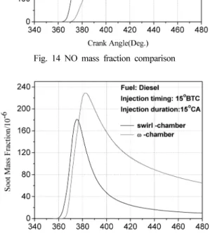
Gas motion within the engine cylinder is one of the major factors controlling the fuel-air mixing and combustion pro- cesses in diesel engines. In this paper, a special swirl-chamber is designed and applied to a DI (direct injection) diesel engine to generate a strong swirl motion thus enhancing gas motion. Compression, combustion and expansion strokes of this DI diesel engine with the swirl-chamber have been simulated by CFD software. The simulation model was first val- idated through comparisons with experimental data and then applied to do the simulation of the spray and combustion process. The velocity and temperature field inside the cylinder showed the influences of the strong swirl motion to spray and combustion process in detail. Cylinder pressure, average temperature, heat release rate, total amount of heat release, indicated thermal efficiency, indicated fuel consumption rate and emissions of this DI diesel engine with swirl-chamber have been compared with that of the DI diesel engine with ω -chamber. The conclusions show that the engine with swirl- chamber has the characteristics of fast mixture formulation and quick diffusive combustion; its soot emission is 3 times less than that of a ω -chamber engine; its NO emission is 3 times more than that of ω -chamber engine. The results show that the DI diesel engine with the swirl-chamber has the potential to reduce emissions.

1. Introduction

Gas motion within the engine cylinder is one of the major factors that controls the fuel-air mixing and combustion processes in diesel engines. The swirl, incline swirl and squish are three kinds of large-scale rotating flow patterns within the cylinder. These flows are strongly dependent on the inlet port, valve, and cylinder head geometry. During the intake or the compression process, these flows become unstable and break down into three-dimensional turbulent motions. Both the bulk gas motion and the turbu- lence characteristics of the flow are important.

To enhance gas motion, much research has been conducted over a long period of time. Tindal, M. J. et

al investigated the effect of inlet port design and found that helical ports normally impart more angu- lar momentum at medium lifts than do directed ports (1) . Brandl, F. et al. conducted an investigation about the swirl modification within the cylinder and came to the conclusion that swirl ratios in bowl-in- piston and flat-topped piston engine designs are dif- ferent and the tangential velocity into the bowl will increase rapidly toward the end of the compression stroke (2) . Shimamoto, Y. et al. compared the squish velocities in bowl-in-piston combustion chambers with different bowl diameter/bore ratios and clear- ance heights (3) .

Many researches also studied IDI (indirect injec- tion) diesel engines to enhance air motion (4-7) . The IDI diesel engine is a typical engine using a prechamber to obtain a strong swirl flow (both in the prechamber and the main chamber) and the swirl is used to pro- mote more rapid mixing and speed up the combus- tion process. In an IDI diesel engine swirl is created

(2010

8

12

일접수

~2010

9

20

일심사완료

, 2010

9

27

일게재확정

)

* Dept. of Mechanical Engineering, Dong-A University, Korea

† Dept. of Mechanical Engineering, Dong-A University, Korea

E-mail : [email protected]

(2)

swirl flow, the IDI diesel engine generates less pollu- tion and less noise while still producing a good per- formance at a high speed. But compared with DI (direct injection) combustion engines, the IDI engines have larger heat transfer surfaces and separate pre- chambers. Also IDI still has disadvantages such as a high fuel consumption rate and a difficult engine start.

In this paper, the advantages of both IDI diesel engines and DI diesel engines are combined. Instead of the prechamber inside the cylinder head, a special swirl-chamber is designed inside the cylinder. This swirl-chamber in the DI diesel engines and the pre- chamber in the IDI diesel engines have similar func- tions. With the movement of the piston, a strong swirl motion can be created in the swirl-chamber. As a result, the swirl will influence the air-fuel mixing rate and combustion process. It also influences com- bustion efficiency and engine emissions.

The main purpose of this paper is to investigate the influences of the strong swirl flow generated by the swirl-chamber on the air-fuel mixing rate and com- bustion process of DI a diesel engine, and find out if this kind of new swirl-chamber design is good for combustion efficiency and engine emissions. For this purpose, both numerical simulation methods and experimental methods were used. CFD software was used to simulate the spray and combustion process.

An engine experimental system was set up and then cylinder pressure and temperature data were mea- sured. Good agreement between calculated and mea- sured results is obtained to validate calculation models.

The velocity and temperature field have been obtained by this simulation and then analyzed in detail to see the influences of the strong swirl flow on the spray and combustion process. Some combustion charac-

2. Design of swirl-chamber

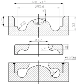
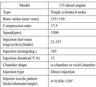
A special swirl-chamber is designed and applied to the DI diesel engine. Figure 1 shows the structure drawing of swirl-chamber. This piston is consisted of two parts and these two parts screwed together. A high platform is set in the center of the reentrant bowl-in-piston combustion chamber. In this way, a ringy passage is formed and the swirl-chamber is made. There are some important geometrical param- eters for this swirl-chamber design. Radius of swirl- chamber is the parameter to control the volume ratio of swirl-chamber to main chamber and the width of passage influences the swirl velocity in the swirl- chamber. Different values lead to different spray and combustion characteristics. In this paper, radius of swirl-chamber and the width of passage are 10 mm and 4 mm respectively.

Figure 2 is a sketch map of the DI diesel engine

Fig. 1 Structure drawing of swirl chamber

(3)

with this swirl-chamber. With the motion of the pis- ton, the flow into the swirl-chamber during the com- pression process creates the rotating flow. Fuel is injected into this swirl-chamber through passage, and then air-fuel mixing and combustion start in the swirl-chamber. The strong swirl and squish flow accelerate the air-fuel mixing process and well mixed gas can be obtained in a short time. After self-igni- tion, the high pressure and temperature mixture rushes out of the swirl-chamber to the main chamber through the ringy passage and then mix with the fresh air in the main chamber. Eventually the fuel burns completely in the main chamber.

3. Simulation for DI diesel spray and combustion process with swirl-chamber

The CFD software is used to simulate the spray and combustion process of this DI diesel engine with swirl-chamber.

3.1 Setup of calculation mesh

Our calculation was performed between the inlet valve closure (IVC) and the exhaust valve open (EVO). Because it is a centric and rotational sym- metric combustion chamber, and the fuel mass flow is the same for all the holes of the injector, only a segment of the geometry for one injected spray is used. According to the number of holes in the injec-

tion nozzle, we use 1/4 cylinder to simulate. The Fig- ure 3 shows the calculation mesh.

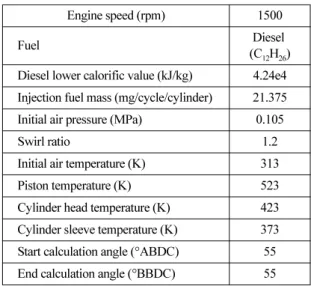
3.2 Initial and boundary conditions

The specification of in-cylinder conditions at IVC is done by the initialization of gas temperature, gas pressure or gas density. The gas temperature and pressure can be measured directly. The gas density is calculated automatically if the gas temperature and pressure are known (equation of state).

The specification of wall surface temperatures (cylinder liner, cylinder head, and piston) was based on experimental experiences and depended on the load and speed operating condition. The boundary condition of the cylinder head was specified as a fixed wall, and the boundary condition of the piston bowl was specified as a moving wall. Table 1 shows

Fig. 2 Sketch map of DI diesel engine with swirl-chamber

Fig. 3 Calculation mesh

Table 1. Initial and boundary conditions

Engine speed (rpm) 1500

Fuel Diesel

(C 12 H 26 ) Diesel lower calorific value (kJ/kg) 4.24e4 Injection fuel mass (mg/cycle/cylinder) 21.375 Initial air pressure (MPa) 0.105

Swirl ratio 1.2

Initial air temperature (K) 313

Piston temperature (K) 523

Cylinder head temperature (K) 423

Cylinder sleeve temperature (K) 373

Start calculation angle (°ABDC) 55

End calculation angle (°BBDC) 55

(4)

the nozzle hole diameter.

For the low Weber numbers, the break-up time is:

(1) and the stable drop radius is:

(2) For the high Weber numbers, the break-up time is:

(3) and the stable drop radius is:

(4) where Λ is the wavelength and is the growth rate.

The model WALLJET1 was used to describe what happens if droplets hit the wall. The angle of reflec- tion and the droplet diameter were changed accord- ing to a function of the Weber number (9) .

(5) The Zeldovich model was used as a NOx forma- tion model (10) . In combination with the Magnussen combustion model or CFM model, the NO formation rate is based on temperature distribution. The reac- tion mechanism can be expressed in terms of the extended Zeldovich mechanism:

(6)

The Kennedy_Hiroyasu_Magnussen model was

equation. is the nucleation source. is the sur- face growth source. is the oxidation source.

Nucleation source:

(8) Surface growth source:

(9) Chemical kinetic oxidation source:

(10)

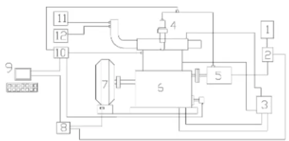
4. Setup of experimental system and validation of calculation models

To validate the calculation models, experimental system was set up. In this study, a single cylinder

τ 0.82 B 1 ρ a 3

--- σ

=

r min 3 ( πa 2 U 2 ) 0.33 3 a 2 Λ 4

( ) 0.33

⎩ ⎭

⎨ ⎬

⎧ ⎫

=

τ = ( B 1 a U ⁄ ) ρ 1 ⁄ ρ 2

r B = 0 Λ

We 50:d<

1

=d

0

50 We 140:d≤ ≤

1

=(1.07 1.01 10× ×

2

×We×3.29 10×

5

×We

2

) d⋅

0

140 We 300:d≤ <

1

=0.416 10×

( 1.02 10 ×

3

× We )

×d

0

we 300:d>

1

=0.2d

0

O N + 2 k 1 NO N +

N O + 2 k 2 NO O +

N OH + k 3 NO N +

S n S g

S O 2

S n C n exp – ( f fn ) 2

σ n 2

---

⎩ ⎭

⎨ ⎬

⎧ ⎫

=

S g A F f φ ( ) p , 0.5 exp – RT --- E a

⎩ ⎭

⎨ ⎬

⎧ ⎫

⋅ ⋅ ⋅

=

S O 2 = – F φ ( s , p O 2 , T ) S O 2 = – F φ ( s , P O 2 , τ )

Table 2. Specifications of diesel engine

Model 135 diesel engine

Type Single cylinder,4-stoke

Bore×stoke (mm×mm) 135×150 Compression ratio 17.5

Speed(rpm) 1500

Injection fuel mass

(mg/cycle/cylinder) 21.357 Injection timing(deg.) 345 Injection duration(°CA) 15

Chamber shape ω -chamber or swirl-chamber Injection type Direct injection

Injector nozzle pattern

(holes/diameter/angle) 4×0.036×150°

(5)

135 diesel engine was used as an experimental engine. Table 2 gives the engine main specifications.

Figure 4 shows a schematic diagram of the experi- mental apparatus. The FC2000 engine automatic measuring and control system makes the engine function in certain working conditions. The AVL combustion analyzer can measure the average pres- sure and temperature inside the cylinder.

The cylinder pressure and temperature data were measured. Figure 5 shows a comparison of the simu- lation result and experimental data for ω -chamber engine. The two average pressure curves are almost same except peak pressure. The peak pressure of simulation is a little higher than that of experiment.

Figure 6 shows a comparison of the simulation result and experimental data for swirl-chamber engine.

Good agreement is obtained except a little difference.

The difference maybe is caused by a slight engine leakage, turbulence model error, boundary condition, calculation methods or experimental apparatus accu- racy.

The comparisons of experimental and calculated diesel engine performances are shown in Table 3. It can be observed from Table 3 that the relative error of power and BSFC (brake specific fuel consump-

tion) between experimental data and calculated result is less than 2.8% and the relative error of NOx and soot emissions is less than 7.7%. These results indi-

Fig. 4 Schematic of experimental apparatus

Fig. 5 Contrast of simulation result and experiment data for

ω -chamber engine

Fig. 6 Contrast of simulation result and experiment data for swirl-chamber engine

Table 3. comparisons of experimental and calculated diesel engine performances

Experimental date Calculated result Relative error/%

Power/kW

13.2 13.5 2.27

BSFC/g·kW −1 ·h −1

255 250 1.96

NOx emission/ppm

1180 1090 7.63

Soot emission/BSU

1.05 1.13 7.62

(6)

345°CA to 380°CA. The velocity in a plane through the cylinder axis and a circumferential radial plane is shown. With the movement of the piston, the strong radially inward squish flow before TDC and outward squish flow after TDC at the bowl lip are apparent.

A clear counter-clockwise swirl is formed in the swirl-chamber. When the piston moves close to the TDC, the velocity of the swirl is about 40 m/s near the swirl-chamber wall. High swirl velocity is good for fuel-air mixing inside the cylinder and it can also prevent the fuel from adhering to cylinder wall.

The flow is forced into the swirl-chamber during

in the regions above high platform and near the bowl lip. Although these small vortexes just last for a short time and then disappear, they also have a great effect on fuel-air mixing.

5.2 Temperature field

Figure 8 shows the temperature field during the spray and combustion process. At 360°CA, a high temperature area is observed at the bottom of the swirl-chamber, which means the fuel is self-ignited.

Heat is released, and the temperature becomes higher rapidly. At 370°CA, the flame rushes out of swirl-

Fig. 7 Axial and radial velocity field in combustion chamber Fig. 8 Temperature field for DI diesel engine with swirl-

chamber

(7)

chamber into the main chamber. At 390°CA, fuel has almost burned inside the main chamber, the tempera- ture inside the main chamber is around 2000K.

5.3 Characteristics comparison

For studying the advantages and disadvantages of swirl-chamber engine, the combustion process of the engine with a ω -chamber was also simulated. Fig. 9 shows the shape of the ω -chamber. This ω -chamber has the same diameter, volume and compression ratio with the swirl-chamber. The only difference between the ω -chamber and the swirl-chamber is the chamber shape.

Figure 10 to Figure 15 show engine characteristics comparison between the swirl-chamber and the ω - chamber. Self-ignition in swirl-chamber engine occurs earlier than in the ω -chamber engine. This is because the strong swirl accelerates the fuel-air mixing rate and therefore shortens the ignition delay.

Figure 10 shows that the top average pressure of

the swirl-chamber engine is higher than in the ω - chamber, which illustrates that more vapor-air mix- ture is formed during the shorter ignition delay

Fig. 9 Shape of ω -chamber

Fig. 10 Pressure comparison

Fig. 11 Temperature comparison

Fig. 12 Heat release rate comparison

Fig. 13 Accumulated heat release comparison

(8)

becomes very low, which means combustion has almost finished. The ω -chamber engine’s diffusive combustion starts at about 380°CA, and the heat release rate is lower. Figure 13 shows the total heat release comparison between the two kinds of cham- bers. The swirl-chamber engine’s total heat release is more than in the ω -chamber, which indicates the combustion is completer.

and low oxygen concentration region, so the peak amount of soot is smaller. In addition, the swirl-cham- ber has good diffusive combustion, so most of the soot is oxidized during diffusive combustion process and there is little soot in the exhaust gases.

6. Conclusion

A special swirl-chamber was designed and studied in this paper. The experimental engine was the single cylinder 135 diesel engine and the CFD software was used to simulate the spray and combustion process of the DI diesel engine with a swirl-chamber. The fol- lowing conclusions were acquired from this study.

1. The average pressure contrast between the sim- ulation result and experimental data verified the availability of the calculation models.

2. The velocity field shows that with the move- ment of the piston, and a counter clockwise swirl is formed in the swirl-chamber. The velocity of the swirl is about 40m/s near the swirl-chamber wall when the piston moves close to the TDC.

3. Temperature field show that air-fuel mixing starts in the swirl-chamber and combustion starts at the bottom of the swirl-chamber. After combustion, the flow of fuel, air, and burning and burned gases rush out of swirl-chamber and into the main chamber with high speed.

4. By the comparisons of combustion characteris- tics between the swirl-chamber engine and the ω - chamber engine, we came to the conclusion that the swirl-chamber engine has rapid mixing and fast dif- fusive combustion. Soot emission of the swirl-cham- ber engine is lower, but NO is higher than in the ω - chamber engine.

Fig. 14 NO mass fraction comparison

Fig. 15 Soot mass fraction comparison

(9)

Acknowledgements

This work was supported by the Dong-A Univer- sity research fund.

References

(1) M. J. Tindal, T. J. Williams and M. Aldoory, “The effect of inlet port design on cylinder gas motion in direct injection diesel engines”, Flow in Internal Combustion Engines, ASME, New York, 1982, pp. 101~111.

(2) F. Brandl, I. Reverencic, W. Cartellieri and J. C. Dent,

“Turbulent air flow in the combustion bowl of a DI diesel engine and its effect on engine performance”, SAE paper 790040, SAE Trans., Vol. 88, 1979.

(3) Y. Shimamoto and K. Akiyama, “A study of squish in open combustion chambers of a diesel engine”, JSME, Vol. 13, No.63, 1970, pp. 1096~1103.

(4) R. Hadef and B. Lenze, “Effects of co- and counter- swirl on the droplet characteristics in a spray flame”, Chemical Engineering and Processing: Process Intensi- fication, Vol. 47, No. 12, 2008, pp. 2209~2217.

(5) P. G. Hill and D. Zhang, “The effects of swirl and tum-

ble on combustion in spark-ignition engines”, Progress in Energy and Combustion Science, Vol. 20, No. 5, 1994, pp. 373~429.

(6) D. T. Li, R. Xiong and H. Xue, “Temperature measure- ment in the swirl chamber of an IDI engine using Moire deflectometry”, Applied Thermal Engineering, Vol.

19, No. 5, 1999, pp. 543~554.

(7) Stevan Nemoda, Vukman Bakic, Simeon Oka, Goran Zivkovic and Nenad Crnomarkovic, “Experimental and numerical investigation of gaseous fuel combustion in swirl chamber”, International Journal of Heat and Mass Transfer, Vol. 48, No. 21~22, 2005, pp. 4623~4632.

(8) LIU A B, MATHER D and REIYZ R D, “Modeling the Effects of Drop Drag and Breakup on Fuel Sprays”, SAE Paper 930072, 1993.

(9) J Senda, M Kobayashi, S Iwashita and H Fujimoto,

“Modeling of Diesel Spray Impingement on a Flat Wall”, SAE Paper 941894, 1994.

(10) Kunpeng Qi, Liyan Feng, Xiabyin Leng, Baoguo Du and Wuqiang Long, “Simulation of quasi-dimensional combustion model for predicting diesel engine perfor- mance”, Applied Mathematical Modelling, Vol. 35, No.

2, 2011, pp. 930~940.

(11) AVL LIST GmbH, “AVL FIRE 8.2 Manual-Theory”,

Graz, Austria, 2003.

수치

Figure 2 is a sketch map of the DI diesel engine
Table 1. Initial and boundary conditions
Table 2. Specifications of diesel engine
Figure 6 shows a comparison of the simulation result and experimental data for swirl-chamber engine.
+3

참조

관련 문서

The purpose of this study is to investigate the effect of online shopping mall characteristics on direct purchasing satisfaction of foreign consumers and purchase

The purpose of this study is to investigate the effect of the “problem solving and programming” area of ​​information subject on perception and

The purpose of this study is to examine the effects of flow experience through the dance sports media, a dance sports image, and identification on

The purpose of this study is to investigate the effect of peer-mentoring on the achievement and learning attitudes of middle school students toward

This study aims to analyze the process and the features of corporate e-Learning as a form of informal learning. For this purpose, the concept of

For very simple flows (no swirl or separation) converge with second order upwind and k-ε model. „ If the flow involves jets, separation, or moderate swirl, converge solution

In addition, it is the purpose of this study to analyze social and historical background and the characteristics on the establishment of the varied

It was found that the NO emission decreased significantly at various condition of operation with the 2-stage combustion type diesel engine, but CO and