In-Car Video Stabilization using Focus of Expansion
Jin-Hyun Kim†, Yeul-Min Baek††, Jea-Ho Yun†††, Whoi-Yul Kim††††
ABSTRACT
Video stabilization is a very important step for vision based applications in the vehicular technology because the accuracy of these applications such as obstacle distance estimation, lane detection and track- ing can be affected by bumpy roads and oscillation of vehicle. Conventional methods suffer from either the zooming effect which caused by a camera movement or some motion of surrounding vehicles. In order to overcome this problem, we propose a novel video stabilization method using FOE(Focus of Expansion). When a vehicle moves, optical flow diffuses from the FOE and the FOE is equal to an epipole. If a vehicle moves with vibration, the position of the epipole in the two consecutive frames is changed by oscillation of the vehicle. Therefore, we carry out video stabilization using motion vector estimated from the amount of change of the epipoles. Experiment results show that the proposed method is more efficient than conventional methods.
Key words: In-car Video Stabilization, Focus of Expansion, Epipole
※ Corresponding Author : Whoi-Yul Kim, Address : (133-791) Annex of engineering center 704-1, Hanyang University, Haengdang-Dong, Seongdong-Gu, Seoul, Republic of Korea, TEL : +82-2-2220-0351, FAX : +82- 2-2292-6316, E-mail : [email protected]
Receipt date : Oct. 31, 2011, Revision date : Dec. 19, 2011 Approval date : Dec. 21, 2011
††††Department of Electronics and Computer Engineering, Hanyang Univ.
(E-mail: [email protected])
††††Department of Electronics and Computer Engineering, Hanyang Univ.
††††Hyundai Mobis Co., Ltd.
(E-mail: [email protected])
††††Department of Electronics and Computer Engineering, Hanyang Univ.
1. INTRODUCTION
In order to prevent vehicle accidents caused by driver’s inattentiveness, DAS(Driver Assistance System) using a camera installed in the vehicle has been extensively studied in the vehicular technol- ogy field. FCWS(Forward Collision Warning Sys- tem), LDWS(Lane Departure Warning System) and PCWS(Pedestrian Collision Warning System) are among the researches that are related to this field. The FCWS is designed to warn the driver or to break the vehicle by force when there is a potential collision with vehicle in front of the host
vehicle. The LDWS is a system which prevents dangerous lane departure of the vehicle by sending a warning signal to the driver when the vehicle leaves the lane without turning on the signal light.
The PCWS prevents the risk of collision by warn- ing the driver of the danger of an incoming collision with a pedestrian in front of the car. DAS uses camera calibration to estimate the distance be- tween the host vehicle and the vehicle in front of the host vehicle. Camera calibration is also used to get lane information as well. However, the per- formance of algorithms such as object detection, distance estimation, and tracking are degraded be- cause the extrinsic parameters of the camera are changed by the road condition or the vibration of the vehicle. Therefore, video stabilization is needed as a pre-processing step to improve the perform- ance of DAS using the camera.
EIS (Electronic Image Stabilization) and DIS (Digital Image Stabilization) methods are two ma- jor categories of the image stabilization methods which can be applied to the image acquired from camera installed in the vehicle. EIS method esti- mates motion vector from angular rate sensor and then using the information obtained to compensate
the image[1]. However, this method faces two main problems that make it undesirable. The first one is an economical problem that arises due to the need to install additional mechanical devices. The second one is a time delay problem which is caused by the mechanical movements of the device. On the other hand, DIS methods use image processing techniques to handle video stabilization. Methods which use information about edge histograms[1], feature points[1], lanes[2], and phase correla- tions[3] are typical examples of the DIS methods.
Due to the zooming effect, it is hard to estimate the precise movements of the vehicle by using edge histogram method. The feature point method fails when the features from two frames don't match each other properly. We can apply the method which uses information about lanes only when lanes exist in the image. The phase correlation method estimates motion by calculating the phase correlation of a predefined ROI (region of interest) of two consecutive frames. This method works fine if the car in front of the host vehicle is fairly stable.
However, problem arises when the car in front of the host vehicle experiences shock or vibration due to the unstable road condition or road bumps.
This paper proposed a video stabilization method that uses motion vector estimated from the amount of change of the epipoles of two consecutive frames in order to overcome the side effects such as zoom- ing effects by camera movements, and motion of surrounding vehicles.
This paper is organized as follows. Section Ⅱ explains about the position change of the FOE caused by vibration of the vehicle. Section Ⅲ de- scribes the video stabilization method using the change of the epipole. Section Ⅳ presents the ex- perimental results for demonstrations. Section Ⅴ gives conclusions of this paper.
2. POSITION CHANGE OF FOE BY VIBRATION OF THE VEHICLE
The coordinate of the camera installed in the ve-
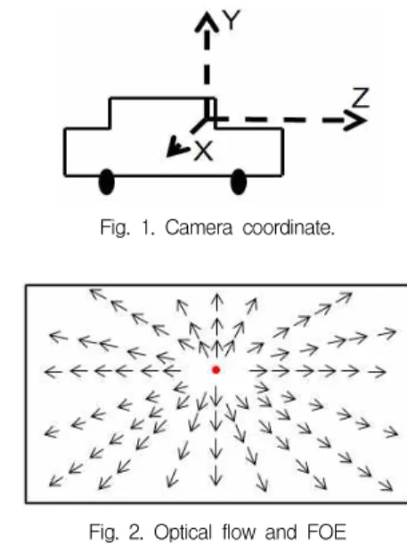
hicle is defined as Fig. 1.Z-axis translation occurs when the vehicle moves in the forward direction.
Pitch and rolling is caused by either road condition or movement of the vehicle. Yaw is caused by in- tentionally steering of the vehicle. In this paper, yaw caused by intentionally steering and static state of vehicle are ignored. Rolling is also ignored to simplify calculation. In the case of pure trans- lation toward Z-axis, optical flow between two successive frames obtained by the camera is dif- fused from an FOE as shown in Fig. 2.
Fig. 1. Camera coordinate.
Fig. 2. Optical flow and FOE
Fig. 3(a) shows the case when the vehicle purely moves in the forward direction. When this happens the FOE positions of the two consecutive frames will be equal as shown in Fig. 3(c). When pitch occurs due to vibration, such as Fig. 3(b), the FOE positions at the two consecutive frames will be dif- ferent as shown in Fig. 3(d). The FOE is always equals to the epipole in a frame[4]. So in this paper, we calculate the epipole in a frame to get the FOE and estimate the motion vector from the amount of change of the epipole at the two consecutive frames. The projection matrix and the epipole can be expressed as Eq. (1) and Eq. (2), respectively[4].
WhereK is the intrinsic parameter, R is the rota- tion parameter andt is the translation parameter.
(a)
(b)
(c) (d)
Fig. 3. Position change of the epipole by camera translation and rotation (a) pure translation by Z-axis, (b) pure translation by Z-axis and rotation by X-axis, (c) position change of the epipole at (a), (d) position change of the epipole at (b).
Fig. 4. The change of the epipole by degree of X-axis
Then, the amount of change of the epipole is ex- pressed by Eq. (3). We can assume K=K'=I, be- cause intrinsic parameter at the camera installed in the vehicle has not changed. In the case of pure translation like Fig. 3(a), the epipole position has not changed becauseR is equals to I. In the case of pitch, motion vector is estimated by the amount of change of the epipole in they-axis of the frame.
Fig. 4 shows the relation between a motion vector estimated by the amount of change of the epipoles in they-axis of the frames and degree of X-axis of camera coordinate. If degree of X-axis in- creases, the amount of absolute change of the epi- pole will also increase.
′ ′ (1)
′ ′ (2)
′ ′ (3)
Fig. 5. Flow chart of the proposed method.
(a) (b)
Fig. 6. (a), (b) Mismatched problem and feature extraction region
3. VIDEO STABILIZATION USING CHANGE OF THE EPIPOLE
Fig. 5 shows a flow chart of the proposed stabi- lization method. We can divide the flow chart into two parts: the motion estimation part and the mo- tion compensation part. The motion estimation part calculates a motion vector. This will be explained in section 3.1. We then perform video stabilization using compensated motion vector which is ob- tained from the motion vector calculated earlier.
3.1 Motion Estimation
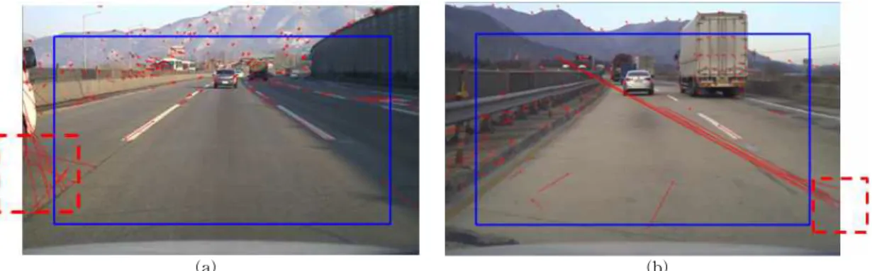
In order to estimate motion vector in the video, we extract feature points from the previous frame using KLT algorithm[5], and then[6,7]. Mismatched feature we get the corresponding points in current frame using optical flow of the feature point prob- lem arises when the feature points located on the boundary of the frame disappear. In order to solve
this problem, we exclude the feature points ex- tracted from boundary of the frame. Fig. 6 shows a mismatched feature point problem and a feature extraction region.
We then calculate the fundamental matrix from the remaining corresponding points using normal- ized 8-point algorithm using RANSAC[4]. From Eq. (4), we are able to calculate the epipole, where F is the fundamental matrix and e is the epipole.
We can obtain the motion vector by solving Eq.
(5), whereFOE.y(i) is the y coordinate of the epi- pole in current frame andFOE.y(i-1) is the y coor- dinate of the epipole in previous frame.
(4)
(5)
3.2 Motion Compensation
In order to stabilize the video sequence of an in- car camera, we need to find the compensated mo- tion vectorCMV(i) in the opposite direction of mo-
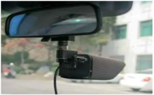
Fig. 7. Installed camera in the car.
Method RMSE
phase correlation [3] 0.22
proposed method 0.22
Table 1. RMSE comparisons of phase correlation and the proposed method(When the vehicle in front of the host vehicle did not experience vibration)
tion vector and we use kalman filter[8] to obtain a stable motion vector.
The kalman filter provides an estimate to the state of a discrete-time process defined as a linear
dynamical system in the form of
× , where is the process noise. The kalman filter operates using measure- ments defined by × , where
is the measurement noise. Process and measure- ment noise are assumed to be independent, white, and with normal probability distributions.
In this paper, the state of the image stabilization system is represented by vertical position of image coordinate and velocity. So, the transition matrix is defined by
(6)
The measurement matrix is defined by
(7)
4. EXPERIMENTAL RESULT
In this section, the performance of the proposed method is evaluated and compared to the other ex- isting method based on the compensated motion vector. To do this, we installed camera in the ve- hicle as shown in Fig. 7, and captured real video sequences by an in-car camera.
We manually find the vanishing line of the ex- tracted frames, and then we can get the ground truth by finding the difference of the vanishing line
in they-axis between previous frame and current frame. The ground truth is given by
′ (8) wherevanish.y(i-1) is the y coordinate of the van- ishing line in the previous frame andvanish.y(i) is they coordinate of the vanishing line in the current frame. The performance is evaluated based on the root mean square error(RMSE) between the phase correlation method and the proposed method. The RMSE is given by
RMSE
′ (9) whereCMV(i) is the compensated motion vector generated from the proposed method at i frame, CMV(i)’ is the motion vector of ground truth at i frame and N is the number of frame. The pro- posed method is compared to the phase correlation [3].
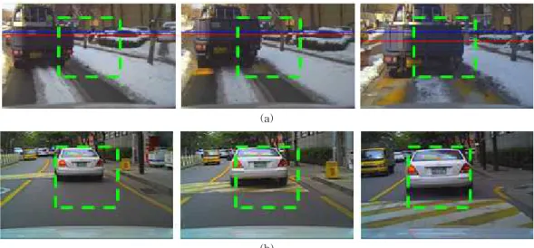
The RMSE results of these two methods are summarized in Table 1. The performance of the proposed method is equal to the phase correlation method in most cases. However, if the vehicle in front of the host vehicle experienced vibration due to the crossing of a speed bump as shown in Fig.
8, the phase correlation method gives a wrong mo- tion vector because this method estimates motion vector based only on a predefined ROI. However, the proposed method ignores the motion of the ve- hicle in front of the host vehicle due to RANSAC algorithm. In this case, TheRMSE results of these two methods are shown in Table 2. Fig. 9 shows the comparison of ground truth and the compen- sated motion vectors by two different methods which are the proposed method and the phase cor-
Method RMSE phase correlation [3] 6.63
proposed method 1.09
Table 2. RMSE comparison of phase correlation and the proposed method(When the vehicle in front of the host vehicle experienced vibration)
(a)
(b)
Fig. 8. (a), (b) Motion which generated at vehicle in front of the host vehicle.
Fig. 9. Compensated motion vector comparison.
relation method. The x-axis represents frame numbers and the y-axis represents the compen- sated motion vector. From the result shown in Table 2 and Fig. 9, we can conclude that the pro- posed method is more efficient than phase correla- tion method.
V. CONCLUSION
In this paper, we proposed a novel video stabili- zation method used by in-car cameras. We get an epipole using corresponding points in two consec- utive frames, and then we estimate a motion vector by the amount of change of the epipoles. The com- pensated motion vector which is used to carry out video stabilization can be obtain from the estimated motion vector. Experiment results have shown that the proposed method is more efficient than the con- ventional method because of its property to elimi- nate mismatched corresponding points and motion of surrounding vehicles.
REFERENCES
[ 1 ] L. Bombini, P. Cerri, P. Grisleri, S. Scaffardi, and P. Zani, “An Evaluation of Monocular Image Stabilization Algorithms for Automo- tive Applications,” Proc. IEEE Conference on Intelligent Transportation Systems, pp. 1562- 1567, 2006.
[ 2 ] Y.M. Liang, H.R. Tyan, S.L. Chang, H.Y.M.
Liao, and S.W. Chen, “Video Stabilization for a Camcorder Mounted on a Moving Vehicle,”
IEEE Transactions on Vehicular Technology, Vol.53, Issue 6, pp. 1636-1648, 2004.
[ 3 ] Y. Zhang, M. Xie, and D. Tang, “A Central Sub-image Based Global Motion Estimation Method for In-Car Video Stabilization,” Proc.
Third International Conference on Know- ledge Discovery and Data Mining, Phuket, Thailand, pp. 204-207, 2010.
[ 4 ] R. Hartley and A. Zisserman, Multiple View Geometry in Computer Vision, Cambridge University Press, second edition, 2004.
[ 5 ] C. Tomasi and J. Shi, “Good Features to Track,” Proc. IEEE Computer Society Confer- ence on Computer Vision and Pattern Recognition, pp. 593-600, 1994.
[ 6 ] J.Y. Bouguet, “Pyramidal Implementation of the Lucas Kanade Feature Tracker Descrip- tion of The algorithm,” Intel Corporation, Microprocessor Research Labs, OpenCV Documents, 2000.
[ 7 ] J.K. Lee and C.J. Park, “Algorithm for Arbitrary Point Tracking using Pyramidal Optical Flow,” J. of Korea Multimedia Society, Vol.10, No.11, pp. 1407-1416, 2007.
[ 8 ] G. Welch and G. Bishop, “An introduction to the kalman filter,” in SIGGRAPH, Course 8, 2001.
Jin-Hyun Kim
Mar. 2002~Feb. 2010 Depart- ment of Electronics Engineer- ing, Keimyung University, B.S.
Mar. 2010~Present Department of Electronics and Computer Engineering, Hanyang Uni- versity, M.S.
Interest : Intelligent Vehicle, Image Processing
Yeul-Min Baek
Mar. 1999~Feb. 2005 Depart- ment of Electronics and Com- puter Engineering, Hanyang University, B.S.
Mar. 2005~Feb. 2007 Depart- ment of Electronics and Com- puter Engineering, Hanyang University, M.S.
Mar. 2007~Present Department of Electronics and Computer Engineering, Hanyang University, Ph.D.
Interest : Intelligent Vehicle, HDR Imaging, Contrast Enhancement, Noise Reduction
Jae-Ho Yun
Mar. 1997~Feb. 2004 Depart- ment of Electronic Engineering, sogang University, B.S.
Sep. 2005~Aug. 2007 Depart- ment of Electronic Engineer- ing, Sogang University, M.S.
Interest : Image Processing, Computer Vision
Whoi-Yul Kim
Mar. 1976~Feb. 1980 Depart- ment of Electronics Engineer- ing, Hanyang University, B.S.
Sep. 1981~May 1983 Depart- ment of Electrical Engineer- ing, Penn. State University, M.S.
Sep. 1984~May 1989 School of Electrical engineering, Purdue University, Ph.D.
Sep. 1989~Feb. 1994 Erilk Jonnson School of Engin- eering and Computer Science, Texas University, Assistant Professor
Mar. 1994~Present Department of Electronics and Computer Engineering, Hanyang University, A- ssistant Professor, Associate Professor, Tenured Professor, Dean Professor.
Interest : Visual Surveillance, Face Tracking and Identification, Motion Analysis, Face Recognition, MPEG-7