LS-DYNA 코드의 유체-구조 연성해석 기법을 이용한 자유낙하식 구명정의 가속도 응답 추정
배동명
1,†․ 자키
1․ 김학수
1․ 김주곤
2부경대학교 조선해양시스템공학과
1동명대학교
2Estimation of Acceleration Response of Freefall Lifeboat using FSI Analysis Technique of LS-DYNA Code
Dong-Myung Bae1,†․ A.F.Zakki1․ Hag-Soo Kim1․ Joo-Gon Kim2
Dept. of Naval Architecture and Marine Systems Engineering, Pukyong National University1 TongMyong University2
Abstract
During certification of freefall lifeboats, it is necessary to estimate the injury potential of the impact loads exerted on the occupants during water entry. This paper focused on the numerical simulation to predict the acceleration response during the impact of freefall lifeboats on the water using FSI(Fluid-Structure Interaction) analysis technique of LS-DYNA code. FSI problems could be conveniently simulated by the overlapping capability using Arbitrary Lagrangian Eulerian(ALE) formulation and Euler-Lagrange coupling algorithm of LS-DYNA code. Through this study, it could be found that simulation results were in relatively good agreement with experimental ones in the acceleration peak values, and that the loading conditions were very sensitive to the acceleration responses by the experimental and simulation results.
Keywords : Free fall Lifeboat(자유낙하식 구명정), Acceleration Response(가속도 응답), FSI(Fluid-Structure Interaction, 유체-구 조 연성), ALE(Arbitrary Lagrangian Eulerian) Formulation(ALE 정식화), Coupling Algorithmn(연성 알고리즘)
1. Introduction
The freefall lifeboats have been designed for a fast and reliable evacuation system. Once the lifeboat departs from the parent vessel, it is simply sliding from a skid before freefall. Several seconds later after its freefall into the water, the propulsion system can start and the lifeboat can sail away from the parent vessel. After the lifeboat is fully submerged into the water during its water entry, and it moves forwards with high speed right after rebounding from the water. Occupants could be affected by the impact loads with high accelerations during this water entry, which have been recently identified with concerns.
In 2009, Hyundai Lifeboat developed the freefall lifeboat for the 35 persons evacuation system. At the first design step of the new lifeboat, the model test had been carried out for the evaluation of the acceleration response level to occupants during its water entry. Impact loads during water
entry could result in some injury potential to occupants. The injury level could be reduced by the lifeboat design according to the several parameters, such as the hull shapes, mass distributions, and the impact points on the water surface. New design of lifeboat should be assessed and compared with IMO standards considering these parameters(IMO., 2003).
Only few experimental results for the freefall lifeboats have been published on the acceleration responses(Arai, et al., 1995) and the their dynamics using derrick boom(Raman, et al., 2005). in 1990's, the pure theoretical researches have been carried out for the basic water entry and exit problems using Computational Fluid Dynamics(CFD)(Morch, et al., 2008). Only two studies could be found for the lifeboats using numerical simulations. The freefall lifeboat launching kinematics were simulated using DYNA3D code, such as its structural response and occupant impact response with a rigid body lifeboat model and no consideration of water,
assuming just one loading condition,(Frazer-Nash Consultancy Limited, 1992). The effects of several parameters were considered for the evaluatiton of lifeboat behavior using Lifeboat Analysis System(LAS), such as its longitudinal center of gravity(LCG) conditions(either forward or backwards), ramp offset and ramp angle(Eliot, 2004).
The best way of water entry problem of the freefall lifeboat to the water could be treated as the Fluid-Structure Interaction(FSI) problems, such as slamming(Lee, et al., 2008 a,b, 2010) and sloshing(Lee, et al., 2010), etc., and should be validated by the experiment. These FSI problems could be conveniently simulated using Arbitrary Lagrangian Eulerian (ALE) formulation and Euler-Lagrange coupling algorithm of LS-DYNA code(LSTC, 2009). Volume of Fluid(VOF) method is adopted for solving a broad range of nonlinear free surface problems and coupling algorithm is more suitable for the FSI problems with very complicated structure, where fluid grid can overlap the structural mesh(Aquelet, et al., 2003, 2006; Souli, et al., 2000).
The objective of this paper is to estimate the acceleration responses of freefall lifeboat using FSI analysis technique of LS-DYNA code, and to validate them with experimental results. Four loading conditions were considered for the water entry experiments of the freefall lifeboat on to the water according to the occupant distribution in the lifeboat, and these four loading conditions were also studied in the numerical simulations as major parameters. ALE approach and Euler-Lagrange coupling algorithm of LS-DYNA code were also adopted for the FSI analysis in this study.
2. Freefall Experiments of Lifeboat
Freefall Experiments of the 1/5 scaled 35 person lifeboat model were performed on the calm sea for the acceleration responses with free drop after short sliding on the skid.
Four loading conditions were considered according to the occupant distribution in the lifeboat.
Two measuring points of accelerometer in the 1/5 scaled lifeboat mode and its coordinate system are shown in Fig. 1.
The coordinates system for the measurement in the lifeboat was aligned with the horizontal position, where the x-axis pointed towards the front of the lifeboat, the y-axis, laterally, and the z-axis, upwards. The two sets of accelerometers were mounted at the measuring points 1 and 2 in the lifeboat, as shown in Fig. 1, where one 3-axial accelerometer was located on the point 1, and three 1-axial accelerometers, on the point 2. Measuring systems are shown in Fig. 2 with detailed specifications.
Fig. 1 Measuring points of accelerometer and coordinate system
Fig. 2 Measuring systems
Fig. 3 illustrates the sketch of the freefall behavior of lifeboat including short sliding on the skid with the launch height 4.5m(22.5m in the case of real lifeboat). Freefall experiments were carried out for the measurement of the acceleration responses of lifeboat according to IMO require- ments, such as the following four loading conditions:
1. Full(100%) loading conditions with full complement of persons(LCG = 3975mm from AP)
2. 50% forward loading conditions with occupants so as to cause the center of gravity(CG) to be in the 50%
forward position(LCG = 4371mm From AP)
3. 50% afterward loading condition with occupants so as to cause the CG to be in the 50% afterward position(LCG=
3559mm From AP)
4. Empty loading condition with its operating crew only(LCG
= 3946mm from AP)
Fig. 3 Sketch of freefall behaviour of lifeboat after short sliding on skid
3. IMO Criteria using SRSS Method
In lieu of the evaluation with the dynamic response model,
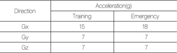
the injury potential for an occupant in a freefall lifeboat is evaluated by the acceleration using the Square Root Sum of the Squares acceleration(SRSS) method. The limiting values incorporated into the revised recommendation for testing lifeboats by IMO are 15g(Gravity) in the x-axis and 7g in the other axes, as shown in Table 1. The SRSS criteria formula is the Eq.(1) as follow:
≤ (1)where,
CAR = Combined Acceleration Response Index
gx, gy, gz = the concurrent accelerations in the x, y and z seat axes
Gx, Gy, Gz = Allowable acceleration
Table 1 SRSS acceleration limits for lifeboat
Direction Acceleration(g)
Training Emergency
Gx 15 18
Gy 7 7
Gz 7 7
The Combined Acceleration Response(CAR) is a measure of the potential for the acceleration to cause human injury. It is varied according to the time and it is computed from acceleration time histories measured in the axis of the seat at the seat support. Before computing the CAR time-history, the acceleration time histories are filtered with 20.0 Hz low pass filter because higher frequency accelerations are not generally injurious. The peak value of the CAR time history is called the CAR Index. Injury should not occur if the CAR Index is less than IMO criteria(IMO, 2003).
4. FSI Analysis Technique of LS-DYNA code
In FSI problems, fluid is usually represented by solving Navier-Stokes equations with an Eulerian or ALE formulation.
FSI can be simulated using a fluid-structure coupling algorithm, such that fluid is treated on a fixed or moving mesh using an Eulerian or ALE formulation and the structure on a rigid or deformable mesh using a Lagrangian formulation. Since ALE approach is based on the arbitrary movement of a reference domain as a third one in addition to the common material and spatial ones, it controls the mesh geometry
independently from material geometry(Aquelet, et al., 2003, 2006; Souli, et al., 2000).
The coupling algorithm computes the coupling forces at the fluid-structure interface. These forces are added to the fluid and structure nodal forces, where fluid and structure is solved using an explicit finite element formulation. The Euler- Lagrange coupling algorithm uses a penalty coupling similar to penalty contact in Lagrangian analyses, as shown in Figs.
4 and 5, respectively(Aquelet, et al., 2006).
Fig. 4 Sketch of penalty coupling algorithm(Aquelet, et al., 2006)
Fig. 5 Sketch of penalty contact algorithm(Aquelet, et al., 2006)
In FSI problems with interface between different materials such as fluid and air, the distortion of the Lagrangian mesh makes many re-meshing steps for the continued calculation.
Eulerian formulation can be used to create easily an un- distorted mesh for the fluid domain. However, this approach requires settling two problems, such as the interface tracking and the advection phase. To solve these problems, an explicit finite element method for the Lagrangian phase and a finite volume method for the advection one are used(Aquelet, et al., 2003, 2006; Souli, et al., 2000).
There are two approaches to implement the ALE equ- ations, such as solution of the fully coupled equations for computational fluid mechanics handling a single material in an element and reference of an operator split for each time step into two phases with the first Lagrangian phase and the second advection phase. Contrary to the Lagrangian phase, in the second advection phase, transport of mass, internal energy and momentum across cell boundaries are computed; this may be thought of as remapping the
displaced mesh at the Lagrangian phase back to its original or arbitrary position element. The VOF method is attractive for solving a broad range of non-linear problems in fluid and solid mechanics, because it allows arbitrary large deformations and enables free surfaces to evolve(Aquelet, et al., 2003, 2006; Souli, et al., 2000).
5. Simulation Modeling
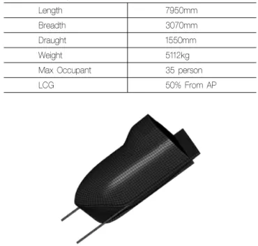
Numerical simulations were carried out using LS-DYNA Version 9.71 R4.2 with single precision. The principal dimension of the lifeboat is shown in Table 2. Outer surface of the lifeboat model was modeled using 4,805 rigid quadrilateral shell elements for the minimization of computational time, and skid was also modeled with rigid quadrilateral shell elements together for the full-scale freefall simulation on the water, as shown in Fig. 6. Their material properties sum - marized in Tables 3 and 4. Among the three contact options,
Table 2 Principal dimension of free fall lifeboat
Length 7950mm
Breadth 3070mm
Draught 1550mm
Weight 5112kg
Max Occupant 35 person
LCG 50% From AP
Fig. 6 Configuration of F.E. mesh of lifeboat and skid models
Table 3 Steel properties of skid
Steel
Density(kg/m3) 7,850
Elastic modulus(GPa) 205
Poisson's ratio 0.30
Table 4 FRP properties of lifeboat
FRP
Density(kg/m3) 2,080
Elastic modulus(GPa) 9.7
Poisson's ratio 0.35
such as kinematic constraint method, penalty method and distributed parameter method, the second one, as shown in Fig. 5, was adopted for the contact between the lifeboat and skid.
Fluids modeling consists of two parts, such as sea water and air, using 182,000 hexagonal Eulerian elements, whose dmensions are 15.0×31.2×2.0m and 15.0×31.2×13.0m, res- pectively, as shown in Fig. 7. Fine mesh, 0.3×0.3×0.3m of fluid element was used around at the free surface with mesh size increment of bias 0.2(??) along the vertical direction.
Fig. 7 Configuration of F.E. mesh of fluid model
There are several commands and options for the fluid modeling and coupling algorithm using FSI analysis technique of LS-DYNA code in addition to the structural modeling and contact option. For fluid modeling, 3D fluid element is usually considered, and element formulation can be usually selected between two element formulation parameters, ELFORM, 11 (1-point ALE multi-material element) and 12(1-point ALE single- material and void) in SECTION_SOLID command. ELFORM 12 was adopted in this study.
For the fluid material description, MAT_NULL command and Equation of State(EOS) have to be defined. Material properties for the sea water is shown in Table 5. In this study, EOS_LINEAR_POLYNOMIAL, EOS was used for the sea water by defining the C1 parameter as bulk modulus of sea water.
Table 5 Material properties of sea water
Sea water
Density(kg/m3) 1,025
Bulk modulus(GPa) 2.2
Viscosity(Pa.s) 1.79E-2
Several parameters are very sensitive to the coupling between the fluid and structure in CONSTRAINED_LAGRANGE_
IN_SOLID command, as shown in Fig. 4. Coupling leakage and penalty forces, etc., are affected by the penalty factor, No. of quadrature coupling points on a Lagrangian segment
and the mesh size ratio between the structure and fluid.
Additionally, continuum treatment and advection method can be selected in CONTROL_ALE command.
The boundary condition of fluid model and constraint condition of structure are also important to the acceleration responses of freefall lifeboat water entry on to the water.
The following assumptions were considered as follows:
1. Only gravitational external load was applied to the whole system using a load curve for the gravitational accele- ration time history.
2. Top, side and bottom boundaries of the fluid were fixed to the normal directions and were set free to the other directions.
3. Initial velocity of lifeboat was set to zero.
6. Validation of Freefall Simulation Results
The acceleration response of lifeboat was used for the assessment of the occupant injury potential. The simulation results with high frequency signals were filtered using a Butterworth digital 8.0 Hz low pass filter. The acceleration responses of simulation for the x-axis, y-axis and z-axis directions are compared with those of experiment in Figs. 8
∼11 according to loading conditions, such as full, 50%
forward, 50% backward and empty loading conditions, res- pectively. Their peak values are also summarized in Table 6.
Based on the experimental results, it was found that the most severe responses were obtained from 50% backward loading condition, which could be explained that the CG of loading condition was shifted to the backward. While the shift of CG to 50% backward caused the righting moment arms to be increased and also led to reduce the severity of slamming phase, the situations were conversed by its shift to 50% forward.
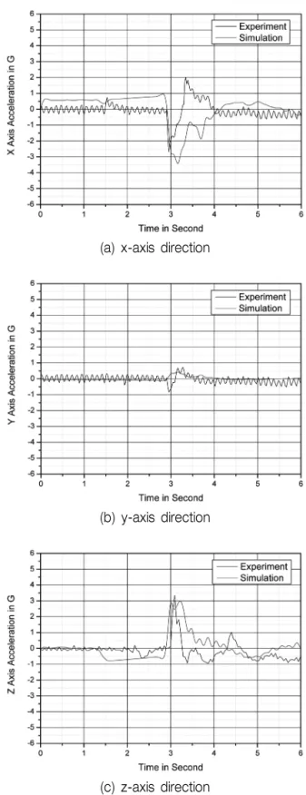
The characteristics of the longitudinal(x-axis direction) acceleration responses were shown to be almost similar in pattern on the experimental results, as shown in Figs. 8~
11(a). This pattern could be due to the bow entry into the water at the vicinity of 3.0 sec and then due to the its rebounce from the water at 0.4 sec later. However, this rebounding phenomenon could not be found in the simul- ation results. Their peak values could be found to be relatively larger than those of experimental results. However, these over values are still acceptable, since their peak values are still below the IMO standards, as shown In Table 1.
As can be seen in Figs. 9∼11(b), the lateral(y-axis direction)
(a) x-axis direction
(b) y-axis direction
(c) z-axis direction
Fig. 8 Acceleration response in full loading condition
acceleration responses occurred very little on the experimental results, while only a small track of the bow impact was shown at the vicinity of 3.0 sec in the case of full loading condition, as shown in Fig. 6(b). Relatively much smaller tracks of the bow impact appeared at the vicinity of 3.0 sec in the all loading conditions of simulation results, as shown in Figs. 8∼11(b).
(a) x-axis direction
(b) y-axis direction
(c) z-axis direction
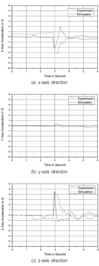
Fig. 9 Acceleration response in 50% forward loading condition
The characteristics of vertical(z-axis direction) acceleration responses could be also found to be similar in pattern on the experimental results, as shown in Figs. 8∼11(c), where the first large peak might be caused by the bow impact to the water at the vicinity 3.0 sec, and the second small one at 1.2∼1.5 sec later. While the first peak value was the
(a) x-axis direction
(b) y-axis direction
(c) z-axis direction
Fig. 10 Acceleration response in 50% backward loading condition
largest in the 50% backward loading condition, the second one, in the empty one. Their peak values and the interval time of the second ones might depend on their CG positions according to the loading conditions, and their entry depths into the water due to their weights. The second peak responses were not be found in the simulation results,
(a) x-axis direction
(b) y-axis direction
(c) z-axis direction
Fig. 11 Acceleration response in empty loading condition
and the durations of the first peak responses were also larger than those of experiments. However, their first peak values were almost the same in the experimental and simulation results, as shown in Figs. 8∼11(c) and Table 8.
These peak acceleration values and CAR Indexes in all loading conditions were also found to be accepted by the IMO standards, as shown in Tables 1 and 6.
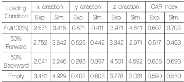
Table 6 Comparison of peak accelerations between experimental and simulation results
Loading Condition
x direction y direction z direction CAR Index Exp. Sim. Exp. Sim. Exp. Sim. Exp. Sim.
Full(100%) 2.671 3.415 0.871 0.411 3.971 4.641 0.607 0.703 50%
Forward 2.752 3.642 0.525 0.442 3.342 2.971 0.517 0.463 50%
Backward 2.041 3.246 0.295 0.397 4.501 4.592 0.658 0.693 Empty 3.481 4.929 0.402 0.603 3.778 3.031 0.590 0.550
7. Conclusions
The objective of this paper was to estimate the accele- ration responses of 1/5 scaled 35 persons freefall lifeboat model using FSI analysis technique of LS-DYNA code, such as ALE formulation and Euler-Lagrange coupling algorithm, and to validate them with experimental results. Four loading conditions were considered for the water entry experiments of the freefall lifeboat on to the water according to the occupant distribution in the lifeboat, and these four loading conditions were also studied in the numerical simulations as major parameters.
It was found that the acceleration responses of freefall lifeboat were very sensitive to the loading conditions. Even though the characteristics of its acceleration responses could not be represented by the numerical simulation, their peak values were in relatively good agreement with those of experiments. These peak acceleration values and CAR Indexes in all loading conditions were also found to be accepted by the IMO standards.
It was worthwhile to perform the water entry problem using FSI analysis technique of LS-DYNA code, even though some parameters and options were not used and verified properly in FSI analysis.
References
Arai, M. Khondoker, R.H. & Inoue, Y., 1995. Water entry simulation of freefall lifeboat-1st report: Analysis of motion and acceleration. Journal of the Society of naval Architects of Japan, 178, pp.193-201.
Aquelet, N. Souli, M. Gabrys, J. & Olovsson, L., 2003. A new ALE formulation for sloshing analysis. Structural Engineering and Mechanics, 16(4), pp.423-440.
Aquelet, N. Souli, M. & Olovsson, L., 2006. Euler-Lagrange coupling with damping effects: Application to slamming problems. Computer Methods in Applied Mechanics and Engineering, 195(1-3), pp.110-132.
Eliot, B., 2004. Computer Simulation of a Freefall Evacuation System in a Range of Initial Conditions. National Research Council Institute for Ocean Technology.
Frazer-Nash Consultancy Limited, 1992. Feasibility of Computer of the Launch of Freefall Lifeboats. Frazer-Nash Consultancy Limited, Shelsley House Randals Way Leatherhead Surrey KT22 7TX. HMSO Books Publications Center, London.
IMO, 2003, International life-saving appliances code. IMO.
Lee, S.G. Lee, I.H. & Baek, Y.H., 2010. Wet Drop Impact Response Analysis of Cargo Containment System in Membrane-type LNG Carrier using FSI Technique of LS-DYNA. Proceedings of the 20th International Offshore and Polar Engineering Conference, Beijing, China, 3, pp.206-214.
Lee, S.G. Hwang, J.O. & Kim, W.S., 2008a. Wet Drop Impact Response Analysis of CCS in Membrane Type LNG Carriers I: Development of Numerical Simulation Analysis Technique through Validation. Journal of the Society of Naval Architects of Korea, 45(6), pp.726-734.
Lee, S.G., Hwang, J.O., & Kim, W.S., 2008b, Wet Drop Impact Response Analysis of CCS in Membrane Type LNG Carriers II: Consideration of Effects on Impact Response Behaviors.
Journal of the Society of Naval Architects of Korea, 45(6), pp.735-749.
Lee, S.G. et al., 2010. Numerical Simulation of 2D Sloshing by using ALE2D Technique of LS-DYNA and CCUP Methods.
Proceedings of the 20th International Offshore and Polar Engineering Conference, Beijing, China, 3, pp. 192-199.
LSTC, 2009. LS-DYNA User's Manual, Version 971 R4. ivermore Soft Technology Corp., USA.
Morch, H.J. Enger, S. Peric, M. & Schreck, E., 2008. Simulation of lifeboat launching under storm conditions. Proc. of the 6th International Conference on CFD in Oil & Gas Metallurgical and Process Industries, Trondheim.
Raman Nair, W. Simoes Re, A. & Veitch, B., 2005. Dynamic of Lifeboat and Boom in Deployment from Moving Support.
Multi body System Dynamic, 13(3), pp.267-298.
Souli, M. Ouahsine, A. & Lewin, L., 2000. ALE formulation for fluid-structure interaction problems. Computer Methods in Applied Mechanics and Engineering, 190(5), pp.659-675.
배 동 명 A. F. Zakki
김 학 수 김 주 곤