Development and Verification of Technical Criteria for a U-Bridge
Kim, Kyoon-Tai* Kim, Chang-Han
Construction Management & Economy Research Division, KICT, Ilsanseo-Gu, Gyeonggi-Do, 411-712, Korea
Abstract
With the recent acceleration in the adoption of IT in industries, converged Construction-IT has been drawing attention as a new market driver in the IT fusion industry. Despite the simultaneous implementation of U-Cities all over Korea in a manner suiting each city’s own attributes, Technical Criteria to build an optimized IT-infrastructure have not yet been prepared. To solve this problem, a standard for U-City construction should be prepared. This research, therefore, draw sample contents in order to establish and verify the criteria for U-City construction. The findings are expected to be meaningful, in that they would serve as significant data for establishing the criteria for future U-City construction.
Keywords : Converged Construction-IT, Technical Criteria, Ubiquitous, Ubiquitous City, U-City
1. Introduction1)
1.1 Background and Objectives of the Research With the wide use of Information Technology (IT), the convergence of IT with other industrial technologies has been on the rise as a new driver for growth. Of these various convergence technologies, a converged Construction-IT is expected to have the greatest ripple effects. At present, the converged Construction-IT is being widely studied, in fields ranging from machine or material-related hardware field to cost or process-related software field. The technology has been simultaneously studied for Ubiquitous Cities (hereinafter referred to as 'U-Cities') from the spatial and urban perspective.
A U-City refers to a city in which Ubiquitous Services (hereinafter referred to as 'U-Services') to improve the quality of life and the efficiency of the urban are provided through ubiquitous urban
Received : September 1, 2010 Revision received : October 11, 2010 Accepted : October 18, 2010
* Corresponding author : Kim, Kyoon-Tai
[Tel: 82-31-910-0420, E-mail: [email protected]]
ⓒ2010 The Korea Institute of Building Construction, All rights reserved.
infrastructures built using ubiquitous urban technologies in accordance with Article 2 of the
‘Ubiquitous City Construction Act’ in Korea.[1] The U-Service utilized in a U-City, however, has not yet been clearly defined. Accordingly, the range of building the U-City is not clear-cut, and what is worse, no concrete Technical Criteria for converged Construction-IT utilized in a U-City construction have been prepared. The term ‘Technical Criteria’ in the construction industry refers to Design Criteria and Standards for the improvement of technology and the environment, and the securing of a certain level of quality in construction. Therefore, diverse criteria for U-City construction should be prepared before the planning stage of the construction project. The Technical Criteria for U-City Construction (hereinafter referred to as 'U-City Technical Criteria') should also be prepared at the early stage of a U-City planning in order to build the optimized IT infrastructure for a U-City. However, such criteria have not been fully prepared in Korea, which can lead to a great deal of trial and error in the process of building a U-City.[2,3]
The U-City Technical Criteria include the construction-IT converged technologies, which can be
Development and Verification of Technical Criteria for a U-Bridge
expected to be extensive in scope and complex in content. Due to such characteristics, including the development and verification of the Composition Structure, and the U-City Technical Criteria, it is hard for the criteria to be developed within a short period of time. However, it is the most fundamental and urgent for developing a U-City Technical Criteria to develop a Composition Structure for the Technical Criteria.[2,3]
As a consequence, the ultimate objective of this research lies in developing a Composition Structure of the Technical Criteria underlying the U-City construction. To do this, the Composition Structure of the Technical Criteria for a U-Bridge that reflect the characteristics of Construction-IT will be developed, and sample Technical Criteria will also be verified in accordance with the system composed. The Composition Structure and sample Technical Criteria developed can serve as important underlying data for the future establishment of U-City Construction Criteria.
1.2 Method and Scope
In order to develop the Composition Structure of U-City Technical Criteria, the U-Service that can be currently implemented should first be defined, and then the related technologies that can be used for building the U-City should be derived. However, the scope of building a U-City is so wide that the scope of this research is restricted specifically to a U-Bridge.
For the development and verification of the Composition Structure of U-City Technical Criteria, the services that can be available on a U-Bridge are classified, and a scenario for the sample services is also drawn based on the services. Through the work of the scenario, the element factors required for implementing the converged Construction-IT are derived. Based on the analysis of the Composition Structure of Technical Criteria, the Technical Criteria for a U-Bridge are set. Finally, the Composition Structure of Technical Criteria is verified using the sample of the Technical Criteria for a U-Bridge.
2. Analysis of Related Technology Trend
2.1 Construction-IT for a U-City
Recently, the simultaneous development of the economy, culture and society has led to an expansion in the urban functions requested by citizens. In particular, the advent of a U-City, an unprecedented form of city in which IT is fused into the infrastructure, has caused the urban functions to be broadened to incorporate virtual technologies to an actual space via IT. A U-City is defined as a city with a new concept of being made using converged Construction-IT.
2.2 Construction Criteria 1) Classification and Definition
The Construction Criteria refer to criteria for design and construction. The criteria for design and construction are specified in Article 34 of the
‘Construction Technology Management Act’ for improvement of technologies and environment, and securing of the quality and appropriate management of construction. Table 1 below shows the classification and definition of the criteria for building construction.[4]
2) Current Status
As of October, 2009, there are 49 Construction Criteria for construction in Korea in total, including 20 Design Criteria, 18 Standard Specifications and 11 Owner's Specifications.[4] The conventional Technical Criteria are mostly the Specifications by construction related with civil construction and building construction. The Specifications for building construction incorporating IT are only described in some of the Specifications for design and construction standards, such as building electrical facilities. In addition, since the conventional Specifications include only the details for individual equipment or machines, not for the aspect of convergence between Construction and IT, they are insufficient to be defined as converged Construction-IT for a U-City. As a result, there have been almost no Technical Criteria for a U-City established thus far among the criteria for building construction.
Service Description
U-Pole
Sensor data loggers and short- and long-distance wireless communication modules are installed on the streetlight poles at a certain interval to relay the data of surrounding nodes.
Road Surface Sensor and
Liquid Potassium Chloride Spray
Device
By installing sensors that can detect moisture conditions, such as dry, damp, wet and freezing wet, when freezing or water melting is detected from the road, it activates a system to emit liquid potassium chloride or alert drivers.
Visibility Sensor (Fog, yellow
dust, etc.)
Visibility sensors installed in areas that are dangerous in the event of hazardous fog will induce drivers to drive safely by indicating the fog alert or providing deceleration information on a telematics device in vehicles or on variable message signs
Overload
Detection To protect the durability of the Bridge structure, it is installed at tollgates or entry points of bridges
Speed &
Traffic Volume Measurement
An RFID chip that cannot be forged or falsified is installed on a vehicle plate, and an RFID antenna and reader is installed on the upper structure such as a streetlight or variable message sign in order to measure the moving speed of vehicles and the traffic volume in a certain section
Direction andWind Speed Meter Hygro-thermoand
meter
The behaviors of the bridge, including vibration and stretching, are analyzed by measuring wind load and temperature load of the bridge.
Construction Criteria Definition
Design Criteria
The restrictions on conditions of design are specified in order to maintain quality, strength, and performance of the facility or work
Construction Criteria
Standard Specification
Standards for each facility are specified in order to secure the quality and appropriateness of the construction project and the safety of the facility
Owner's Specification
Based on the Standard Specification, it is a comprehensive Specification to be utilized as a construction Specification for a specific organization
3. Construction-IT for U-Bridge
As the subject for this study, a U-Bridge significantly related with roads was selected from among other various infrastructures for a U-City. This chapter identifies the U-Services available on the U-Bridge, and discusses scenarios of the sample service. In addition, converged Construction-IT is selected based on the scenarios.
3.1 U-Bridge Services
In this section, cases of the domestic and overseas applications of converged Construction-IT or ideas to apply such technologies will be discussed, and services will be classified and defined.
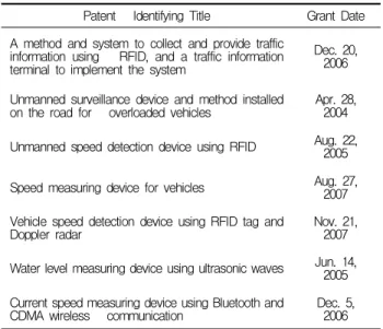
1) Current Status of Technical Patents
Patents related with speeding, water level and provision of traffic information applicable to a bridge among the converged Construction-IT are shown in Table 2 below.
2) Outline and Analysis of Services
This research predicts the possible U-Bridge technologies, and Table 3 shows U-Bridge Services that have been drawn based on the patented and expected technologies.[5]
Patent Identifying Title Grant Date A method and system to collect and provide traffic
information using RFID, and a traffic information terminal to implement the system
Dec. 20, 2006 Unmanned surveillance device and method installed
on the road for overloaded vehicles Apr. 28, 2004 Unmanned speed detection device using RFID Aug. 22,
2005 Speed measuring device for vehicles Aug. 27,
2007 Vehicle speed detection device using RFID tag and
Doppler radar Nov. 21,
2007 Water level measuring device using ultrasonic waves Jun. 14,
2005 Current speed measuring device using Bluetooth and
CDMA wireless communication Dec. 5,
2006
U-Bridge has great dependence on sensors to measure overload, speeding and traffic volume, and also requires the function to send and receive wireless data.[6,7]
Table 3. Summary of the U-Bridge Services
Development and Verification of Technical Criteria for a U-Bridge
Service Description
Acceleration Meter (Vibration)
An acceleration meter is installed on the main span of the bridge to analyze damages or behaviors by measuring the vibration of the bridge.
DisplacementGPS Meter (Deflection)
A GPS displacement meter is installed on the main span of the bridge and on the part where displacement should be measured to measure the deflection and displacement
Water Level Sensor
Supersonic sensors for measuring water level are installed on the main span of the river bridge to measure changes in water level.
Current Speed Detection
Sensor
Propeller-type current speed detecting sensors are attached to lower part of the bridge piers to measure current speed in real time.
Water Quality Sensor
Water quality sensors are attached to lower part of bridge piers to continuously monitor the water quality of the river and allow people to deal with the pollutants detected after they identify the drainage.
3.2. Sample Service Scenario of U-Bridge
In order to derive elemental technologies for a U-Bridge from the enumerated services, service scenarios are needed. From among the diverse services, this research selected ‘the road surface sensor and liquid potassium chloride spray device,’
which is currently being used for Road and Bridge structures in Daegwanryeong area, including bridges on which freezing often occurs in winter. A sample service scenario for the service is made, and the applicability of the converged Construction-IT to an entire U-Bridge Service is derived.
1) Composition of a Sample Service Scenario The sample service, 'the road surface sensor and liquid potassium chloride spray device', is as follows.
In an emergency on a U-Bridge due to snow or freezing wet that can cause a serious traffic accident, a system automatically emits liquid potassium chloride and displays an alert signal for safe driving on the various message signs, or activates a barrier to block incoming traffic, if necessary.
An actual scenario to offer the sample service is as follows. First of all, install road surface sensors that can detect the road's condition of dryness, dampness, wetness or freezing wetness in real time. Next, the
signals of the road's surface conditions are gleaned and analyzed through the data logger. Finally, the data that has been gleaned in this manner is sent to an urban integrated control center, which monitors road conditions by utilizing the data received. The analyzed data is provided to drivers in an appropriate manner, including via a variable message sign, and is also utilized to promptly cope with an emergency by using a road structure, including the activation of a liquid potassium chloride spray or a barrier to block incoming traffic.
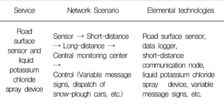
2) Deduction of Elemental Technologies for the U-Bridge Sample Service
The elemental technologies required to implement the service scenario of 'the road surface sensor and liquid potassium chloride spray device' are shown in Table 4.
Table 4. Element Technologies for the Sample Service Service Network Scenario Elemental technologies
Road surface sensor and
liquid potassium
chloride spray device
Sensor → Short-distance
→ Long-distance → Central monitoring center
→Control (Variable message signs, dispatch of snow-plough cars, etc.)
Road surface sensor, data logger, short-distance communication node, liquid potassium chloride spray device, variable message signs, etc.
4. Composition Structure of U-Bridge Technical Criteria
To establish the U-Bridge Technical Criteria, the entire and detailed Composition Structure of the conventional Construction Criteria should be analyzed more than anything else. Based on the elemental technologies, the Composition Structure of U-Bridge Technical Criteria is derived.
4.1 Composition of Conventional Construction Criteria
Construction Criteria vary depending on the objectives and characteristics of the organization in which they were established. Therefore, the scope of
building electrical facility and building mechanical facility related Design and Construction Criteria that have the most in common with the U-Bridge Technical Criteria. The contents of conventional Design and Construction Criteria do not have much in common due to their characteristic of being the results of individual research in a professional field. Worse, in some parts the characteristics of converged Construction-IT are difficult to apply. In this research, to make some corrections and complement some part of the system within the range of maintaining consistency with the Composition Structure of conventional Construction Criteria is analyzed as shown in Table 5.
Table 5. Conventional Composition Structure of Construction Criteria
Constructi
Criteriaon Composition Structure Analysis
Design Criteria
1.1 General 1.1.1 Division 1.1.2 Components 1.1.3 System 1.1.4 Design sequence 1.2 Reference dimensions 1.3 Installation Location 1.4 Equipment performance 1.5 Electric work
·Insufficient detailed Specifications for the work required for technologies
·If the Composition Structure must be complemented, the U-Bridge building Construction Criteria can be applied in detail.
Specificati on
1. General
1.1 Related Specification 1.2 Reference dimension 2. Material
2.1 Components 2.2 Material criteria 3. Construction
3.1 Installation criteria 3.2 Electric work 3.3 On-site quality
management
·Fundamental formation is appropriately maintained according to the guidelines on how to make construction Specification
·Since there is no fixed construction sequence, it will be added to the Composition Structure of the U-Bridge Construction Criteria, if required.
※ Source: Development of Construction-IT Converged Technical Criteria for a U-City through an Analysis of the Conventional Building Construction Criteria of Korea (2009)
To not only maintain consistency with the conventional Construction Criteria but also reflect the characteristics of converged Construction-IT, the major components of the converged construction-IT are derived.
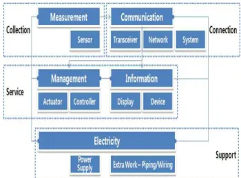
'The road surface sensor and liquid potassium chloride spray device' derived in Chapter 3 consists of 5 major components, including measurement (road surface sensor), IT (data logger, short-distance communication nodes), operating process (liquid potassium chloride spray device), information (variable message signs), and electricity (power). Fig. 1 below indicates the relationship among the five components as collection to play a key role, connection to link with a service, and support to play a supportive role. By identifying the major components and their roles, efficiency and availability can be maximized in establishing the Composition Structure.
Figure 1. Relationship of Major Components
4.3 The Composition Structure of the U-Bridge Technical Criteria
Based on the analysis of the content of conventional Construction Criteria, the Composition Structure of the U-Bridge Technical Criteria is established. The Composition Structure consists of 'Measurement (P01000)', 'Operating Process (P02000)', 'Information (P03000)', and 'Network (P04000)' related with such roles as Collection, Service and Connection of the major components. Both 'IT
Development and Verification of Technical Criteria for a U-Bridge
(C10000)', the linkage role, and 'Electricity (E10000)', a supportive role, are also utilized in other services, and thus are composed separately from the detailed content of infrastructure construction. The principles of the Composition Structure of U-Bridge Technical Criteria are as follows.
In line with the consistency of the Composition Structure of conventional Specification, the items shown in the guidelines for how to write a construction Specification (1999) are included as they are, including 'General', 'Material', and 'Construction', The sub-items are mostly included as they are, but some names of these have been changed. The
‘installation of the instruments', a construction sequence, is additionally added.
Therefore, the Composition Structure of a U-Bridge Technical Criteria includes 4 Chapters, such as General, U-Bridge Construction, U-electrical facility construction, and U-IT facility construction, as shown in Table 6. Here, the criteria applied to a construction project for general bridges are not included, while additional criteria needed to build a U-Bridge only are included.
The role played by each specific work involved in U-Bridge construction is different, but the Composition Structure as a whole follows a general rule. Table 6, therefore, only describes sub-items for measurement control, not those for other specific works.
5. Development of Sample U-Bridge Technical Criteria
In this chapter, the Composition Structure of the U-Bridge Technical Criteria presented in the Chapter 4 is verified by making and assessing a sample U-Bridge Technical Criteria.
5.1 Composition of the Sample
The sample Technical Criteria for the ‘road surface sensor and liquid potassium chloride spray device’
selected is shown in Table 7.
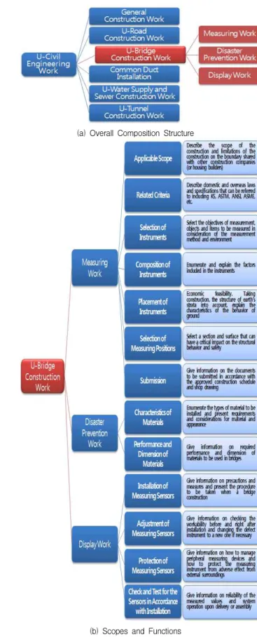
5.2 Overall Outline
The overall outline of the sample U-Bridge Technical Criteria is shown in Fig. 2, including the scope and function. The overall outline set the scope to be covered, which has a great influence on the actual outcome in the form of direction-setting and branches of the initial composition. In addition, it can not only help the construction parties involved in the actual development to more effectively understand one another, but also can serve as the basis for enactment and revision of other Specification.
5.3 Comparative Analysis
It is best to assess efficiency by applying the U-Bridge Technical Criteria in the actual field.
However, due to the practical restrictions in applying the sample to an actual field, a comparative analysis of Composition Structure s between the sample U-Bridge Technical Criteria and the conventional Owner's Specification is used to verify feasibility.
As shown in Table 8, principles such as '1. General',
‘2. Material’ and ‘3. Construction’ are observed, and other items including ‘3.2 Electrical Work’ are mostly included because they are required. Therefore, it is composed to have approximately 80 per cent in common with the conventional Specification in order to maintain consistency with Composition Structure.
However, IT is an important part in the U-Bridge Technical Criteria so that such items as '1.3 Selection of Instruments', '1.5 Placement of Instruments', '3.2 Adjustment of Instruments', are added. This is believed to endow specialty to the U-Bridge Technical Criteria.
The verification method inevitably includes subjective factors, which is a shortcoming. However, the results are believed to be meaningful in that a Composition Structure of Technical Criteria that can be an underlying basis for further research is established.
U-Bridge
Chapter Section Part
G10000 General
G04000 Preparation Construction G01000 Construction General G02000 Construction Planning G03000 Construction Management
P10000 U-Bridge Construction
P01000 Measurement Control 1. General
1.1 Applicable scope 1.2 Related criteria 1.3 Selection of measuring
instruments
1.4 Composition of measuring instruments
1.4.1 Elements of measuring instruments
1.4.2 IT of measuring instruments 1.4.3 Electricity for measuring
instruments 1.5 Placement of measuring
instruments
1.6 Selection of where to measure 1.7 Submission
2. Material
2.1 Characteristics of material 2.2 Performance and dimension of
material 3. Construction
3.1 Installation of measuring instruments
3.2 Adjustment of measuring instruments
3.3 Protection of measuring instruments
P02000 Construction for operating process
1. General 2. Material 3. Construction
P03000 Construction for information provision
1. General 2. Material 3. Construction
P04000 Construction for Network 1. General
2. Material 3. Construction
E10000 U-Electric Facility Work
E01000 General E02000 Pipe Work E03000 Wiring Work
E04000 Power Supply Facilities E05000 Electrical FacilitiesWork
Construction Work E06000 Redundant Power Supply
Facility Construction Work E07000 Active Fire Suppression
System
C10000 U-IT Facility Work
C03000 Auto-control facility work C01000 Construction General C02000 Communication Network
Construction
(a) Overall Composition Structure
(b) Scopes and Functions
Figure 2. Overall Outline of the Sample U-Bridge Technical Criteria
Development and Verification of Technical Criteria for a U-Bridge
1. General 1.1 Applicable Scope
It can be applied to a general construction for a cutting-edge intelligent social infrastructure with which service can be made freely available anywhere and at any time by detecting, communicating and controlling information on objects and the environment from the tags and sensor nodes designed based on the「U-Bridge Design Criteria」to be established in the future and attached to the bridge.
1.2 Related criteria
- Related laws: laws related to construction contracts, Construction Management Related Act (The Road Traffic Act, Urban Traffic Readjustment Promotion Act, Electrical Construction Business Act, Electronic Communication Fundamental Law)
- Related Specifications: Korea Expressway Corporation Standard Specification (Ministry of Construction and Transportation, 2003), Standard Specification for Road Bridges (Ministry of Construction and Transportation, 2005), Standard Specification for General Civil Engineering Projects (Korean Society of Civil Engineers, 2005) - Reference Dimension: Korean Industrial Standards (hereinafter
referred to as KS)
1.3 Selection of road surface sensor
The road surface sensor should have a level of accuracy appropriate for the installation objective, and the performance, durability and calibration should be checked before installation in order to make it easy to install and maintain and to keep the durability at a certain level during the period of use.
1.4 Composition of road surface sensor 1.4.1 Elements
- Road surface sensor
- IT facility (data logger, wire- and wireless communication system) - Electrical Equipment
1.4.2 IT
The communication module should have accuracy and be in the range appropriate for installation objectives.
- Output Signal: RS-485 1.4.3 Electricity
When installing a data collection system that can automatically garner data, a power supply system should be installed in order to stably collect, save and send the measured data, as well as additional equipment including voltage regulator, dehumidifier, thermoelectric module and lightning protection system.
- Bias Voltage: 9~14V DC; less than 200 mA
The conduit and accessories should be completely connected, both electrically and mechanically.
- Depth of the conduit: 0.6(from the surface of the earth when it is in the direction of the road)
- Deeper than 2(when it is across the road) 1.5 Placement of Road Surface Sensors
- The road surface sensors are, in principle, placed at the locations shown on the design drawing. However, if necessary, the locations can be changed through mutual deliberation with the supervisor or construction supervisor to attain the objectives based on the advance review results and the discretion of the technician in charge.
- When the bridge has an entry where traffic accidents frequently occur or begins at a sharply curved road, the sensors are, in principle, placed on the surface to be measured at a certain interval (70m ~200m)
1.6 Selection of the measuring position for road surface sensor A place or area representing a U-Bridge or required for a structure analysis is selected as a measuring position.
1.7 Submission
The data that must be submitted is checked to determine the date of submission in accordance with the approved schedule of construction.
- Commencement plan for construction - Construction schedule
- Construction plan - Detailed shop drawing - Construction picture
- Various written documents for reporting and permission and/or approval.
2. Material
2.1 Characteristics of material
- Quality: SUS304, reinforced nylon, stainless steel
- Appearance: with the water-proof function and the capacity to install a locking device, and metal case and concrete block-shaped metal case
2.2 Performance and Dimension of the material
In principle, products shall have passed the certification test by one the following organizations for testing and certification.
- Korea Testing Laboratory
- Quality Korean Foundation for Quality
- Construction Quality Testing Criteria(No. 2008-83 by Ministry of Land, Transportation and Marine Affairs)
In principle, the materials used for the bridge construction must comply with KS. However, in the event that some materials do not comply with KS, they may be used after approval by the supervisor through the prescribed procedure.
- Pressure: Higher than 30 - Temperature: ~80 °C
- Cable: Serial Cable (for outdoor connection) 3. Construction
3.1 Installation of the road surface sensor - Carry-in of the road surface sensors
: Confirmation and inspection of the sensors (supervisor, person in charge of measurement)
- Decision of where to install the sensors
: Check the locations where the sensors are to be installed, and mark the places using a lacquer
- Drilling and road surface cutting
: Make a hole 16in diameter and 6in depth on the road surface using a core drill. For the burial of sensor cable, cut the road surface to the end side.
- Burial of the road surface sensors
: After burying the sensors in the right position of the drilled holes as described in the installation manual, harden the road surface filled with epoxy and asphalt concrete.
- Burial of the cable
: Upon finishing the installation of sensors, bury the cable along the road cut to the communication equipment, and fill the gap with asphalt concrete and harden it.
- Cable protection and installation completion
: When the installation work is finished, arrange and fix the cable to the communication equipment using some tie.
- Measuring work
: In compliance with frequency of measurement, conduct a measurement of the real-time road surface sensors - Data check
: Check the condition of data after finishing the process of measurement
3.2 Adjustment of the road surface sensors
If necessary, the road surface sensors should be checked to ensure that they work properly, and adjusted before and after the
installation.
- Check and test for the installation of road surface sensors 3.3 Protection of road surface sensors
- The road surface sensors should be substantially installed to endure external impacts, and the external protector should be installed to protect the sensors from breakdown or errors caused by external impact.
- When any of the sensors is found to be broken, it should be reported to a construction supervisor or a supervisor, and then reinstalled.
Table 7. Sample Technical Criteria
Composition
Structure Conventional Owner’s
Specification U-Bridge Specification
1. General
1.1 Applicable Scope 1.1 Related
Specification 1.2 Reference
Dimension
1.2 Related Standard
1.3 Selection of Instruments 2.1 Component 1.4 Composition of
Instruments 1.5 Placement of
Instruments
1.6 Selection of Where to Install
1.7 Submission
2. Material 2.2 Material Criteria
2.1 Characteristics of Materials 2.2 Performance and
Dimension of Material
3. Construction
3.1 Installation
Criteria 3.1 Installation of Instruments 3.2 Electrical Work
3.3 Field Quality
Control 3.2 Adjustment of Instruments 3.3 Protection of
Instruments
6. Conclusion
U-Cities with a range of characteristics have been constructed all over the world. In order to construct be an underlying basis for further research is established.
In this research, working from the premise that a Composition Structure is needed to develop a U-City Technical Criteria, a sample Composition Structure and Technical Criteria was established, specifically for U-Bridges. First of all, to predict Construction-IT, U-Bridge Services were derived. A scenario for the
‘road surface sensor and liquid potassium chloride spray device’ was made, through which elemental technologies to achieve the Construction-IT for U-Bridges were derived. Next, to establish the Composition Structure of U-Bridge Technical Criteria, a variety of standard Specifications and Owner's Specifications were analyzed. Finally, based on the system of conventional Specifications analyzed, the feasibility of the Composition Structure of the U-Bridge Technical Criteria was verified.
From the verification results, the newly developed
common with the format of conventional Specifications, and to appropriately cover the specialty of the converged Construction-IT as well. However, as there are no objective guidelines to evaluate Technical Criteria, the reflection of subjective opinions in an assessment can be a limitation. The results of this research can serve as the underlying data when developing a Composition Structure of Technical Criteria for other U-City facilities, including U-Road, U-Tunnel, and U-Office.
Acknowledgement
This research was supported by a grant (07 Cutting-edge City-A01) from the Construction Technology Innovation Program, funded by Ministry of Land, Transport & Maritime Affairs of Korean government.
References
1. Ubiquitous City Construction Act, May 2008
2. Kim CH, Han JG, Kim KT, The development of Structure of converged construction-IT criteria for the u-city by analyzing domestic construction criteria, 2009 Spring conference of the Korea institute of building construction 2009;9(1):137-41.
3. Kim KT, Han JG, Kim CH, A fundamental study to develop standard technology criteria for it-construction fusion technologies, to be applied to a u-city, ICCEM ICCPM 2009:1352-8.
4. Korea institute of construction technology, Guidelines of how to write construction specification, Ministry of construction and transportation, Nov. 1999
5. Patent office web site, http://www.kipo.go.kr
6. Ubiquitous ecology city R&D center, The 1styearresearchreport,Koreainstituteofconstructionandtrans portationtechnologyevaluationandplanning,2008
7. Ubiquitous ecology city R&D center, The 2ndyearresearchreport,Koreainstituteofconstructionandtran sportationtechnologyevaluationandplanning,2009