Vol. 20, No. 11 (2010)
559
†Corresponding author
E-Mail : [email protected] (J. H. Lee)
Spark Plasma Sintering and Ultra-Precision Machining Characteristics of SiC
Hyeon-Taek Son, Dae-Guen Kim, Soon-Sub Park and Jong-Hyeon Lee*
†Automotive Components Center Team, Honam Technology Application Division, KITECH, Oryong-dong, Buk-gu, Gwangju 500-480, Korea
*Graduate School of Green Energy Technology, and Department of Nano Materials Engineering, Chungnam National University, Yuseong, Daejeon 305-764, Korea
Abstract
The liquid-phase sintering method was used to prepare a glass lens forming core composed of SiC-Al2O3-Y2O3. Spark plasma sintering was used to obtain dense sintered bodies. The sintering characteristics of different SiC sources and compositions of additives were studied. Results revealed that, owing to its initial larger surface area, α-SiC offers sinterability that is superior to that of β-SiC. A maximum density of 3.32 g/cm3 (theoretical density [TD] of 99.7%) was obtained in α-SiC- 10 wt% (6Al2O3-4Y2O3) sintered at 1850oC without high-energy ball milling. The maximum hardness and compression stress of the sintered body reached 2870 Hv and 1110 MPa, respectively. The optimum ultra-precision machining parameters were a grinding speed of 1243 m/min, work spindle rotation rate of 100 rpm, feed rate of 0.5 mm/min, and depth of cut of 0.2µm.The surface roughnesses of the thus prepared final products were Ra = 4.3 nm and Rt = 55.3 nm for the aspheric lens forming core and Ra = 4.4 nm and Rt = 41.9 for the spherical lens forming core. These values were found to be sufficiently low, and the cores showed good compatibility between SiC and the diamond-like carbon (DLC) coating material. Thus, these glass lens forming cores have great potential for application in the lens industry.
Key words
ultra-precision machining, SiC, spark-plasma-sintering, glass lens forming core, sintering.1. Introduction
The lens industry has been growing rapidly because of the recent development of ultra-precision optical devices and camera modules for electronic mobile devices. One of the most important requirements of the lens as a core component of optical devices is a low thermal expansion coefficient with high transparency. Therefore, the raw ma- terial for the lens is very brittle and a high-temperature compaction process is generally used to prepare an inter- mediate product. High-temperature materials have been widely used for the mold base and core part. Tungsten carbide (WC) is a representative material that satisfies all of the characteristics. One disadvantage of WC is its high density, which increases the capacity of related compon- ents such as the compaction press and handling devices because 50 to 80 cores are used in each forming process.
Hence, there is a demand for light core materials to in- crease productivity and economic competitiveness. Silicon carbide (SiC) has been recognized as an alternative core component material because of its lower weight and higher conductivity than WC. However, the problem with SiC is that densification is very difficult without the use of sintering additives, because SiC has strongly covalent
bonds. Kim has reported that the addition of Al
2O
3-Y
2O
3enhances the fracture toughness of sintered SiC.
1)Mulla
2)and Lee
3)have demonstrated that oxide materials are
effective in decreasing the pressureless sintering tempera-
ture and have thus supported Kim’s finding. Lee has
compared the sintering characteristics between α and β-
SiC.
4)Later, Samanta has attempted to analyze the chemical
stability of a SiC-Al-Y-O system during gas pressure
sintering and established the thermodynamic background
for improvement of the sintering process.
5)The aforemen-
tioned study found that sintering temperature is lowered
when metal oxides or nitrides are used as sintering
additives. Sintering in these systems has been proposed to
be controlled by liquid-phase formation. However, further
increase in the density is hindered owing to the intrinsically
low sinterability of SiC. Recently, the spark plasma sin-
tering (SPS) method has been developed for fabricating
metals, ceramics, and composites. Gao et al. has proved
that the relative density of SiC fabricated by SPS can be
increased to upto 98% by adding YAG at 1600°C.
6)Further, Hotta and Hojo have reported that SiC can be
densified using SPS by adding AlN
7)and Song et al.
8)showed the mechanical property improvement of Si
3N
4-
SiC-Y
2O
3composite ceramics. In order to use the sintered
SiC in glass lens forming cores, its machining characteris-
tics should be investigated. To the best of our knowledge,
a comprehensive investigation of the ultra-precision grinding
characteristics of spark-plasma-sintered SiC has not yet been performed. Hence, in the present study, we report the SPS behavior of α and β-SiC with an oxide additive and the optimum processing parameters for grinding the sintered body to use it in glass lens forming cores. Near- net-shaped glass lens forming cores were prepared from the sintered body, and their properties were evaluated after coating with diamond-like carbon (DLC).
2. Experimental Procedure 2.1 Spark plasma sintering of SiC
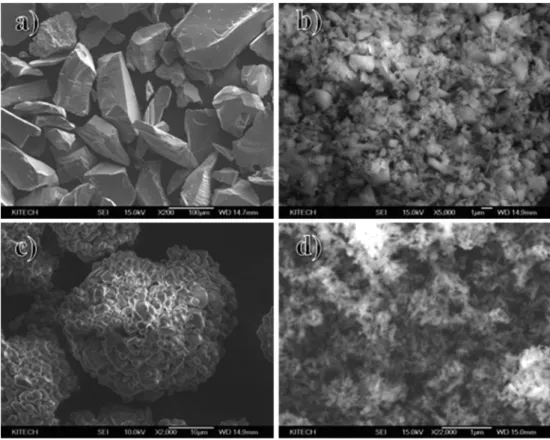
Fig. 1 presents scanning electron microscopy (SEM) microstructures of the powders used in this study. The mean particle sizes of β-SiC (Yakuri Pure Chemicals Co., Japan), Al
2O
3(Samchun Pure Chemical Co., Korea), and Y
2O
3(Samchun Pure Chemical Co.) are 100 µm, 2 µm, and 0.1 µm, respectively. The original β-SiC powder was coarse. The coarse β-SiC was ground to a fineness of less than 10 µm through various milling methods such as ball milling and high-energy ball milling processes (under dry and wet conditions in ethanol) with a rotation speed of 200 rpm for predefined times. The weight ratio of milling balls to powder materials was maintained as 10 to 1. In the case of α-SiC powder (Alfa Aesar-A Johnson Matthey Company, USA), the average particle size was less than 2 µm, which is similar to that of the ceramic additive.
Seven different additive concentrations varying between 0 and 10 wt% were employed at different ratios of Al
2O
3and Y
2O
3without further milling. The additive was chosen because it has various melting temperatures according to composition at relatively low temperatures: 1760°C at Al
2O
3/Y
2O
3= 6:4, 1850°C at Al
2O
3/Y
2O
3= 7:3, and 1940°C at Al
2O
3/Y
2O
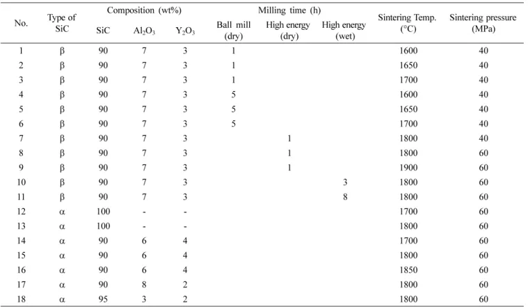
3= 8:2. In the present work, 18 sets of ex- periments were conducted by varying the type of SiC and process parameters, as summarized in Table 1.
SPS was performed using a SPS-515S sintering machine (Sumitomo Heavy Industries Ltd., Japan) under vacuum.
The prepared powder was placed into a graphite die with 10 mm of diameter and 20 mm of height. The pulse duration was 3 ms. One pulse sequence contained 10 pulses, and the interval between pulse sequences was 5 ms. The pulse sequence current averaged 5000 A. The pressure was varied between 40 and 60 MPa, as depicted in Table 1.
2.2 Analysis
The densities of the sintered samples were measured by the Archimedes method. The hardness was measured using a micro Vickers hardness tester. The samples were polished with emery paper up to #2000 and then with a 1 µm dia- mond slurry prior to etching with HNO
3solution. The surface of the polished samples was observed by SEM (JSM 5410, JEOL, Japan) in the backscattered electron (BSE) mode. For measurement of surface roughness, an
Fig. 1. Initial morphologies of raw materials used in this study. a) β-SiC, b) α-SiC, c) Al2O3 and d) Y2O3.
aspheric measuring instrument (Form Talysurf series 2, Taylor Hobson Co., UK), which is a contact type with a 120 mm measuring range and 0.86 nm resolution, was used.
2.3 Ultra-precision machining of sintered SiC and DLC coating
Sintered samples require ultra-precision machining for measurement of surface roughness so the green pellet was prepared larger than the final sample size. An ultra- precision computer numerical control (CNC) machining device (ULG-100C (H3), Toshiba, Japan) was used to obtain the required qualified surface finish of SiC. The machine tool has two high-precision aerostatic bearing spindles (one for the workpiece and one for the abrasive wheel) and a highly rigid V-V horizontal roller guideway.
All straight axes (X, Y, Z) of the machine tool had 1 nm resolution. Various grinding parameters1 were tested in order to identify the optimum grinding parameters.
The DLC-coatings were deposited using an unbalanced RF magnetron sputter system with graphite target. Thus mirror polished SiC samples were used as a substrate material. After the substrates were introduced in a vacuum chamber, the system was evacuated down to < 1 mPa, followed by an Ar flow of 1~5 cm
3/min. The substrate tem- perature and the bias voltage were approximately 25
oC and 100V, respectively, during the deposition.
3. Results and Discussion
Fig. 2 shows SEM BSE images of sintered specimens (Nos. 1-6) fabricated by SPS at different sintering tem- peratures and ball milling times. It is evident that the additive oxide phase is dispersed along the grain bound- aries in all samples. In the case of 1 h ball milling time, Fig. 2(a), interparticular pores prevail throughout the samples, regardless of sintering temperature. When the milling time increased to 5 h, Fig. 2(b), porosity decreases slightly with sintering, but the additive ceramic phase did not fill the pores sufficiently. The SiC particle size in the sintered samples ranges from several tens to hundreds of micrometers based on the microstructure, as shown in Fig. 2. The sinterability of the β-SiC powder in terms of sintering temperature is more quantitatively compared using density and stress variations, as shown in Fig. 3. The density of the specimen sintered at 1600°C and ball milled for 1 h is 2.7 g/cm
3, which is 81% of the theoretical density of 90 wt% SiC (3.21 g/cm
3)-10 wt% [7Al
2O
3-3Y
2O
3(4.3 g/cm
3)]. There are slight increases in the density of speci-mens with sintering temperature; 2.78 g/cm
3is recorded at 1700°C. The compre- ssion stress of specimens sintered at 1650°C and 1700°C is 100 MPa and 125 MPa, respectively. When the ball milling time increased to 5 h, specimen densities increased to 2.95 g/cm
3(89% TD), with sintering at 1700°C. The com- pression stress is more significant compared to density
Table 1. Composition of starting materials and sintering conditions.No. Type of SiC
Composition (wt%) Milling time (h)
Sintering Temp.
(°C)
Sintering pressure (MPa) SiC Al2O3 Y2O3 Ball mill
(dry)
High energy (dry)
High energy (wet)
1 β 90 7 3 1 1600 40
2 β 90 7 3 1 1650 40
3 β 90 7 3 1 1700 40
4 β 90 7 3 5 1600 40
5 β 90 7 3 5 1650 40
6 β 90 7 3 5 1700 40
7 β 90 7 3 1 1800 40
8 β 90 7 3 1 1800 60
9 β 90 7 3 1 1900 60
10 β 90 7 3 3 1800 60
11 β 90 7 3 8 1800 60
12 α 100 - - 1700 60
13 α 100 - - 1800 60
14 α 90 6 4 1700 60
15 α 90 6 4 1800 60
16 α 90 6 4 1850 60
17 α 90 8 2 1800 60
18 α 95 3 2 1800 60
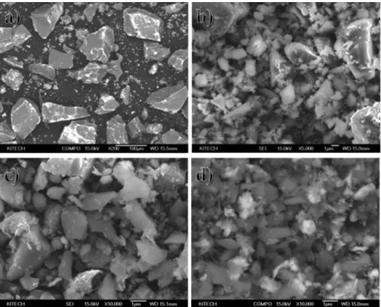
increases, and the maximum stress is recorded as 225 MPa. The material properties of the specimens with the aforementioned sintering conditions are far too low for application to glass lens forming cores. The main reason for these low physical properties is the coarse particle size of SiC, indicating that ball milling is unable to grind the SiC powder finely enough for sintering. Hence, the effect of the high-energy ball milling process was investigated to determine how to obtain better sintering characteristics. Fig.
4 presents SEM images of high-energy ball milled powders under dry and wet conditions. Compared to the initial mixed powder shown in Fig. 4(a), the particle size of SiC was
significantly decreased (mean size is 5 µm) by high- energy dry ball milling for 1 h, as shown in Fig. 4(b).
Finer SiC particles, ~2.5 µm, were obtained by high- energy wet ball milling for 1 h, and the particle size was further decreased to 1.5 µm of mean size with 8 h wet ball milling.
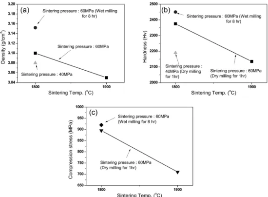
The variations of density and hardness of sintered β-SiC
specimens according to sintering temperature and pressure
are depicted in Fig. 5. The density of the sample decreases
as the sintering temperature increases from 1800
oC to
1900
oC, whereas it increases with sintering pressure
increase from 40 MPa to 60 MPa as shown in Fig. 5(a). In
Fig. 2. SEM BSE images of sintered specimens fabricated by spark plasma sintering at different sintering temperatures and ball milling times (90 wt% β-SiC-10 wt% (Al2O3/Y2O3= 7:3, applied pressure : 40 MPa). (a) Milling time : 1hr and (b) milling time : 5hrs.addition, the density level of the specimens sintered with high-energy ball milled powders is significantly increased to more than 3.05 g/cm
3(91.9% TD) for all specimens, to a maximum of 3.1 g/cm
3(93.4% TD) for the specimen sintered at 1800°C with 60 MPa and dry milled raw material. In the case of wet milled raw material, the density reached 3.15 g/cm
3(95% TD). This agrees well with the powder size refinement of raw materials achieved using a
higher energy milling device, especially under a wet condi- tion for a prolonged milling time, as shown in Fig. 4(d).
The density decrease in the specimen sintered at 1900°C is attributed to the fact that the excess liquid phase was squeezed out of the specimen during sintering, which in- dicates that the sintering temperature was too high. The maximum hardness of 2375 Hv was observed in the sintered specimen (dry milled raw material) at 1800
oC of sintering temperature with 60 MPa of pressure as shown in Fig. 5(b). The hardness decreases as the sintering tem- perature increases to 1900°C. A higher hardness value of 2450 Hv was also achieved in the specimen sintered using the wet milled raw materials for 8 h. The compression stresses of the specimens are less than 920 MPa, which is the maximum value of the specimen sintered with raw material wet milled for 8 h as shown in Fig. 5(c). However, the density and mechanical properties remain unsatisfactory for application to glass lens forming cores. This is also expected from the microstructure data depicted in Fig. 6, which presents SEM images of sintered specimens fabri- cated by SPS with various sintering temperature and pres- sure conditions. Micropores are prevalent throughout the specimens, regardless of the sintering conditions. Even though the coarse particle size of β-SiC is refined by the ball milling process, especially wet milling, a satisfactory level could not be achieved under the sintering conditions.
Fig. 4. SEM images of high-energy ball milled powders under dry and wet conditions a) initial mixed powder, b) dry milled powder for 1 h, c) wet milled powder for 1 h and d) wet milled powder for 8 h.
Fig. 3. Variations in maximum compression strength and density variations fabricated by spark plasma sintering at different ball milling times and sintering temperatures (composition β-SiC-10 wt%
(7Al2O3-3Y2O3), applied pressure: 40 MPa).
Fig. 5. Variations in density and mechanical properties of sintered β-SiC specimens fabricated by spark plasma sintering (β-SiC + 10 wt%
(7Al2O3-3Y2O3), high-energy ball milling under dry condition for 1h). (a) density, (b) hardness and (c) compression stress.
Fig. 6. SEM images of sintered specimens fabricated by SPS with sintering temperature and pressure (β-SiC + 10 wt% [7Al2O3-3Y2O3], high-energy ball milling under dry and wet conditions). a) 40 MPa at 1800°C (dry, for 1 h), b) 60 MPa at 1800°C (dry, for 1 h), c) 60 MPa at 1900°C (dry, for 1 h) and d) 60 MPa at 1800°C (wet, for 8 h).
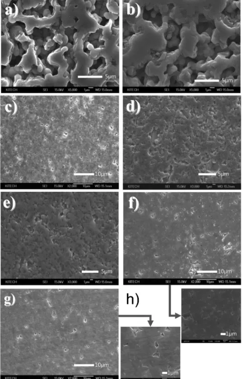
Against this background, a series of sintering experiments was performed with finer raw material to achieve superior physical properties. Fig. 7 presents an SEM image of sintered α-SiC with and without additive powder at various sintering temperatures. No matter how much finer the initial particle size of α-SiC is compared to β-SiC, as shown in Fig. 1, it was difficult to obtain dense sintered specimens with pure α-SiC at both 1700°C and 1800°C
(Nos. 12 and 13, Table 1). Only the necking among parti- cles increased, as shown in Fig. 7(a) and (b). In order to observe variation in the sinterability, various additive ratios were tested, as depicted in Table 1, from Nos. 14 to 18.
In this experiment, α-SiC powder and additive materials were mixed without the high-energy ball milling process, because α-SiC powder was fine enough for sintering, as shown in Fig. 1(b). When an additive was introduced
Fig. 7. SEM images of sintered α-SiC with and without additive powder at various sintering temperatures. a) 1700oC, b) 1800oC: without additive, c) 1700oC, d) 1800oC, e) 1850oC: with 10 wt% (6Al2O3-4Y2O3) powder, f) 1800oC: with 10 wt% (8Al2O3-2Y2O3) powder, g) 1800oC: with 5 wt% (3Al2O3-2Y2O3) powder and h) Magnified images of f) and g).
into the sintering experiment, the degree of porosity was drastically decreased, as shown in Fig. 7(c-g). In the case of 10 wt% addition of 6 wt% Al
2O
3-4 wt% Y
2O
3powder, as shown in Fig. 7(c-e), more dense microstructures were obtained, and micropores were distributed in the speci- mens. When the composition of the additive changed to 8 wt% Al
2O
3-2 wt% Y
2O
3, the porosity was further de- creased, as shown in Fig. 7(f). It should be noted that the micropores observed in Fig. 7(c) nearly disappear as the sintering temperature increased to more than 1800°C.
This is because the composition of the additive of 6 wt%
Al
2O
3-4 wt%Y
2O
3is eutectic and the melting point is 1760°C. Hence, liquid-phase sintering was effectively carried out at a sintering temperature of more than 1800°C, as shown in Fig. 7(d) and (e). When the composition changed to 8 wt% Al
2O
3-2 wt% Y
2O
3, which is 1940°C of melting temperature, large pores reappeared, as shown in Fig. 7(f), as the additive is solid phase at the sintering temperature of 1800°C. In order to evaluate the effect of
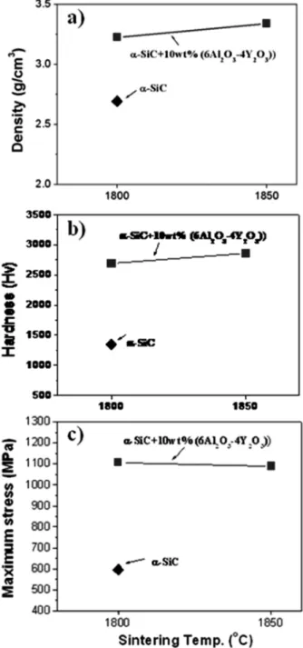
Fig. 8. (a) Density, (b) hardness and (c) maximum strength of sin- tered α-SiC and α-SiC + 10 wt% (6Al2O3-4Y2O3) powder.
Fig. 9. Surface roughness according to ultra-precision machining parameters. a) grinding speed, b) feed rate and c) depth of cut.
the total amount of additive, the content of the additive was decreased to 5 wt% instead of 10 wt% while the composition is maintained at a eutectic composition of 3Al
2O
3-2Y
2O
3. Under this sintering condition, micropores are visible throughout the specimen surface, as shown in Fig. 7(g) and (h) even though the coarse cavity has com- pletely disappeared compared to Fig. 7(f). This may indicate that 5 wt% of additive is insufficient to completely fill the interparticular pores of α-SiC, but the eutectic composition is evidently favorable for the liquid-phase sintering of α- SiC powder.
Density and mechanical properties such as hardness and compression stress were measured for the unique speci- mens sintered with α-SiC + 10 wt% (6Al
2O
3-4Y
2O
3). These properties are compared to the value of pure α-SiC sintered specimen, as shown in Fig. 8
.In the case of the α- SiC specimen sintered at 1800°C without additive, the density is 2.7 g/cm
3(84% TD), whereas it increases to 3.23 g/cm
3(97% TD) with 10 wt% (6Al
2O
3-4Y
2O
3) additive at the same temperature. Further, 3.32 g/cm
3(99.7% TD) of density was recorded at a sintering temperature of 1850°C. Moreover, there were drastic increases in the hardness and compression stress of specimens sintered with 10 wt% (6Al
2O
3-4Y
2O
3) additive: 2870 Hv and 1110 MPa were obtained at 1850°C and 1800°C, respectively.
In order to identify the optimum ultra-precision ma-
chining parameters of the thus-prepared sintered specimen, surface roughness of α-SiC specimen sintered at 1850°C with 10 wt% (6Al
2O
3-4Y
2O
3) was measured according to the machining parameters such as grinding speed, feed rate, and depth of cut, as shown in Fig. 9. The maximum grinding speed of the ultra-precision machine was 1500 m/
min. The surface roughness was thus measured at 942, 1017, 1092, 1168, 1243, and 1318 m/min grinding speed with a 100 rpm work spindle rotation rate, a 0.5 mm/min feed rate, and a 0.2 µm depth of cut. The surface roughness decreased as grinding speed increased up to 1243 m/min;
above this value, it increased. Hence, the effect of work speed on surface roughness was investigated after fixing the grinding speed at the optimum value of 1243 m/min.
The surface roughness maintained the lowest level at around 100 rpm. By combining the obtained grinding and working speed, the other processing parameters were obtained from Fig. 9(c). It is of note that, as shown in Fig.
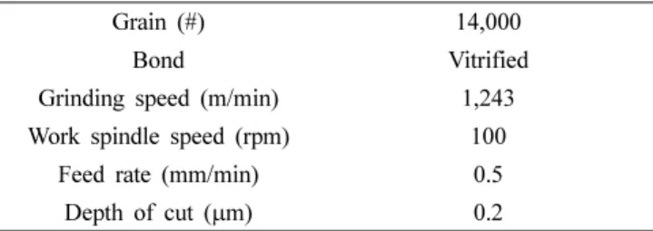
9(c), the surface roughness at a 0.2 µm depth of cut is lower (2.78 nm) than that of a 0.1 µm depth of cut. This is because a stick-slip phenomenon occurred in which un- stable sliding takes place between the workpiece and the grinding media when the depth of cut is too low. The thus- derived optimum machining parameters of SiC sintered specimens are summarized in Table 2.
Fig. 10(a) and (b) shows the prepared final aspheric and spherical lens molding core, respectively, after ultra- precision machining under the conditions listed in Table 2.
Mirror-like surfaces are clearly evident. The surface roughness data measured using the Form Talysurf 2+ are Ra = 4.3 nm and Rt = 55.3 nm and Ra = 4.4 nm and Rt = 41.9 for aspheric and spherical lens surfaces, respectively, as depicted in Fig. 10(c) and (d).
One of the advantages of the SiC lens forming core is that the DLC coating can easily be applied. As such, the mechanical properties of the DLC coating layer for the
Table 2. Optimum machining parameters of sintered SiC specimensfor glass lens forming core.
Grain (#) 14,000
Bond Vitrified
Grinding speed (m/min) 1,243
Work spindle speed (rpm) 100
Feed rate (mm/min) 0.5
Depth of cut (µm) 0.2
Fig. 10. Final aspheric (a) and spherical lens molding core (b) and their surface roughness measurement results (c, d).
final machined specimens were evaluated, as shown in Fig.
11. The thickness of the DLC coating layer is 70 nm with a sound surface finish. Both hardness and modulus measured by nanoindentation increased with the displacement into the surface. Uniform values were obtained upto the interface between the DLC coating and the SiC surface, indicating that the DLC coating was compatible with the prepared SiC specimen.
This result is very promising for the lens-making industry.
The processing parameters obtained in this work may contribute to minimizing the trial and errors in the develop- ment of new glass lens forming core designs.
4. Conclusion
This study shows that α-SiC has superior sinterability than β-SiC owing to its initial larger surface area. The use of an additive with a moderate melting temperature was the most important factor in obtaining high density. A dense specimen (3.32 g/cm
3, TD of 99.7%) of α-SiC-10 wt%
(6Al
2O
3-4Y
2O
3) was obtained by the SPS method at 1850°C without high-energy ball milling. The maximum hardness and compression stress of the sintered body reached 2870 Hv and 1110 MPa, respectively. The optimum ultra-precision machining parameters were a grinding speed of 1243 m/min, work spindle rotation rate of 100 rpm, feed rate of 0.5 mm/min, and depth of cut 0.2 µm. The specimen prepared under these conditions showed a surface rough- ness of 2.78 nm. The surface roughnesses of the final pro- ducts were Ra = 4.3 nm and Rt = 55.3 nm for the aspheric lens forming core and Ra = 4.4 nm and Rt = 41.9 for the spherical lens forming core. The DLC coating deposited on the machined lens forming core surface showed good compatibility with SiC.
References
1. D. H. Kim and C. H. Kim, J. Am. Ceram. Soc., 73(5), 1431 (1990).
2. M. A. Mulla and V. D. Krastic, J. Mater. Sci., 29(4), 934 Fig. 11. SEM images of DLC-coated SiC specimen and hardness and modulus of DLC coating layer. a) cross-section, b) surface and c) hardness and modulus of DLC coating layer.
(1994).
3. S. K. Lee, Y. C. Kim and C. H. Kim, J. Mater. Sci., 29(20), 5321 (1994).
4. S. K. Lee and C. H. Kim, J. Am. Ceram. Soc., 77(6), 1655 (1994).
5. A. K. Samanta, K. K. Dhargupta and S. Ghatak, Ceram.
Int., 27(2), 123 (2001).
6. L. Gao, H. Wang, H. Kawaoka, T. Sekino and K. Niihara, J. Eur. Ceram. Soc., 22(5), 785 (2002).
7. M. Hotta, J. Hojo, J. Eur. Ceram. Soc., 30(10), 2117 (2010).
8. O. S. Song, K. Ando, K. Takahashi, W. Nakao, J. Ryu, Kor.
J. Mater. Res., 15(12), 780 (2006) (in Korean).