1. Introduction
The 800MHz band is interesting in the area of cellular communications; however, there are several problems with miniaturization of microwave devices at this frequency because of the relatively large wavelength [1]. Specifically, metallic waveguide filters operating at 800MHz are heavy and bulky, and integration with base-station antennae is difficult.
Several techniques have been used to decrease filter size, such as the development of dielectric-filled waveguides [2], high-permittivity dielectric resonators [3], or multiple modes [4].
Among these, generation of triple modes in one resonator shows great promise and introduces
the possibility of efficient space utilization, as well as integration with other techniques, for example, a dielectric resonator [5] or microstrip filter [6-7] with triple modes.
This paper proposes a novel triple-mode cavity structure operating at 850MHz, analyzes the field distribution of the proposed cavity is using rigorous electromagnetic software, and describes the operating principles
2. Configuration
Fig. 1 shows the configuration of the proposed cavity. A cylindrical dielectric resonator is positioned in the center of a metallic cylindrical cavity. The
Triple-Mode Characteristics of Cylindrical Cavity Loading a Cylindrical Dielectric Resonator
Seung-Mo Lee*, Cha-Man Kim*, Jong-Chul Park*, In-Ryeol Kim**, Soon-Soo Oh***
Abstract In this paper, a novel triple-mode cavity structure, designed for compactness and operating at 850 MHz, is analyzed. A cylindrical dielectric resonator is loaded into a metallic cylindrical cavity. Previous study has been focused on the analysis of the cylindrical dielectric resonator, but in this paper, the effect of the cylindrical metallic cavity has been analyzed. Enclosing the dielectric resonator inside the metallic cavity increases the resonant frequency of the dielectric resonator; however, this increases the quality factor and introduces the possibility of installing coupling screws. The principle of generation of triple-mode was investigated by parametric analysis. The generated triple-mode is TE011 mode and two orthogonally generated HEM121 modes.
By adjusting the radius of the dielectric resonator, the height of the dielectric resonator, or the radius of the cylindrical metallic cavity, three modes could be coincided. However, the height of the metallic cavity keeps three modes separated. The mode characteristics of the proposed cavity are analyzed using a full-wave electromagnetic (EM) simulation. The proposed triple-mode cavity could be developed to triple-mode filter using a coupling screw, and the commercial application for the miniaturized filter below 1 GHz could be expected.
Key Words : Dielectric resonator, waveguide filter, cavity resonator, triple mode, metallic cavity
This research was supported by a grant from the Advanced Technology Center R&D Program funded by the Ministry of Trade, Industry& Energy of Korea (10048475), and this research was supported by research fund from Chosun University in Korea, 2016.
*Research Laboratory, WAVETECH, Inc.
**Dept. of Electrical Engineering, Chosun University
***Corresponding Author : Dept. of Electrical Engineering, Chosun University([email protected])
Received December 09, 2016 Revised December 15, 2016 Accepted December 25, 2016
radius and height of the dielectric cylinder are RD = 26mm and HD = 48mm, respectively. The cavity encloses the dielectric resonator, which increases the resonant frequency of the dielectric resonator;
however, the quality factor may be increased, and coupling screws may be installed. The radius and height of the metallic cylinder are RC = 45mm and HC = 80mm, respectively.
3. Field Analysis 3.1 Parametric Study
In order to investigate the parametric effect, the commercial software ANSYS HFSS based on a finite element method was used, and the resonant mode was measured directly using the eigenvalue mode analysis embedded function, without applying a feeding structure [8]. The parameters RD, HD, RC, and HC were set to initial values of 26, 48, 45, and 80mm, respectively.
(a)
(b)
Fig. 1 Configuration of the proposed triple-mode cavity. (a) Perspective view, (b) top view
First, the dielectric resonator was examined.
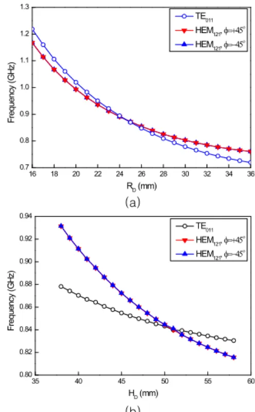
As shown in Fig. 2(a), the radius of the
dielectric resonator RD was swept from 16 to 36mm. The resultant resonant frequency drops from about 1.2 GHz to 700MHz over this range.
This study indicated that the radius RD was the most critical parameter determining the resonant frequency of the cavity. Note that for RD <
25mm, the lowest mode is the TE011 mode, while for RD > 25mm the lowest mode becomes the HEM121 mode. A similar phenomenon was found for the ranges of HD and RC investigated. Therefore, it is possible to excite three modes with identical frequencies in the same space; this, however, requires consideration when designing coupling or feeding structures.
As shown in Fig. 2(b), the height of the dielectric cylinder was swept from 38 to 58mm.
The resonant frequency dropped over this range from about 880 to 830MHz for the TE011 mode, and from 930 to 820MHz for the HEM121 mode.
16 18 20 22 24 26 28 30 32 34 36
0.7 0.8 0.9 1.0 1.1 1.2 1.3
Frequency (GHz)
RD (mm)
TE011 HEM121, f=+45o HEM121, f=-45o
(a)
35 40 45 50 55 60
0.80 0.82 0.84 0.86 0.88 0.90 0.92 0.94
TE011 HEM121, f=+45o HEM121, f=-45o
Frequency (GHz)
HD (mm)
(b)
Fig. 2 Resonant frequency versus dielectric resonator parameters. (a) radius RD, (b) height, HD.
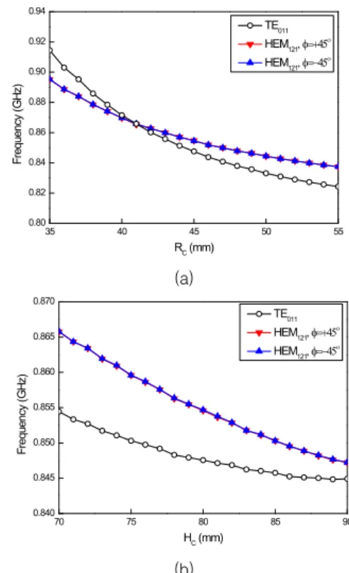
Second, the metallic cylindrical cavity was examined. The radius of the cylindrical cavity RC was swept from 35 to 55mm, as shown in Fig. 3(a). The resonant frequency in this range dropped from about 915 to 825MHz for the TE011 mode, and from 895 to 840MHz for the HEM121 mode. Interestingly, the lowest mode, for RC <41mm is the HEM121 mode.
As shown in Fig. 3(b), the height of the metallic cavity was tuned from 70 to 90mm. The resultant resonant frequency dropped from about 855 to 845MHz for the TE011 mode and from 865 to 845MHz for the HEM121 mode. Compared with other parameters, the smallest frequency variation was observed when changing the height of the cavity, although the energy can be confined to the cavity. The lowest mode was the TE011mode over the full range of heights from 70 to 90mm.
35 40 45 50 55
0.80 0.82 0.84 0.86 0.88 0.90 0.92 0.94
TE011 HEM121, f=+45o HEM121, f=-45o
Frequency (GHz)
RC (mm)
(a)
70 75 80 85 90
0.840 0.845 0.850 0.855 0.860 0.865 0.870
TE011 HEM121, f=+45o HEM121, f=-45o
Frequency (GHz)
HC (mm)
(b)
Fig. 3 Resonant frequency versus metallic cavity parameters. (a) radius RC, (b) height, HC.
3.2 Electric-Field Distribution
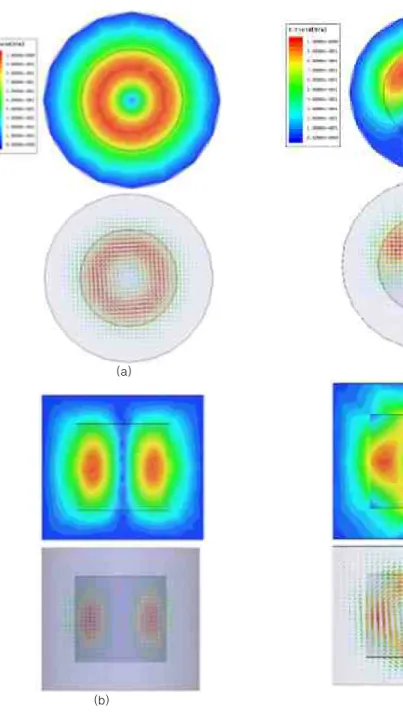
Fig. 4 shows the electric field profile of the TE011 mode resonating at 848MHz. The left hand side shows the magnitude of the contour, and the right hand side shows the vector flow of the electric field. The variation along the azimuthal direction is zero and the variation along the radial direction shows one peak, as shown in Fig. 4(a). The variation along the radial and height directions has one peak, shown in Fig. 4(b).
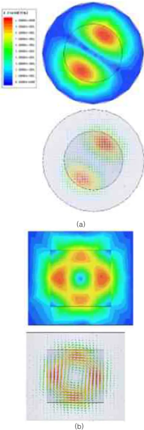
Fig. 5 shows that HEM121φ = +45° has a peak at φ = +45° and Fig. 6 shows that HEM121φ = -45° has a peak at φ = -45°, and the electric field distribution is similar, but rotated through 90 degrees. As they are orthogonally degenerated modes, their resonant frequencies are identical [9]. Since the variation along the cavity height has one peak, the generated mode is denoted the HEM121 mode rather than the HEM12δ mode. This convention is also applied to the TE011 mode.
(a)
(b)
Fig. 4 TE011 mode of proposed cavity. (a) y-z plane, (b) x-y plane.
(a)
(b)
Fig. 5 HEM121φ = +45° mode of proposed cavity. (a) y-z plane, (b) φ = +45° plane.
(a)
(b)
Fig. 6 HEM121φ = -45° mode of proposed cavity. (a) y-z plane, (b) φ = -45° plane.
4. Conclusion
This paper proposed a triple-mode cavity, designed for compactness and operating at 850MHz and a performed parametric study, including a field distribution analysis. A cylindrical dielectric resonator is loaded in order to generate the TE011 mode and two degenerated HEM121 modes. The mode characteristics of the proposed cavity were analyzed using full-wave electromagnetic (EM) simulation. By adjusting the radius of the dielectric resonator, the height of the dielectric cylinder, or the radius of the cylindrical cavity, three modes could be coincided. The proposed triple-mode cavity could be developed to triple-mode filter using a coupling screw.
REFERENCES
[1] X. Zhang, Q. Wang, H. Li, and R. Liu, “E vanescent mode compact waveguide filte r,” in International Conference on Microw ave and Millimeter Wave Technology, Na njing, China, pp. 323-325, Apr. 2008.
[2] K. Wakino, T. Nishikawa, T. Ishikawa,
“Miniaturization Technologies of Dielectri c Resonator Filters for Mobile Communic ations,” IEEE Trans. Microwave Theory and Techniques, vol. 42, no. 7, pp. 1295-1 300, Jul. 1994.
[3] I. Awai, “Artificial Dielectric Resonators f or Miniaturized Filters,” Microwave Maga zine, vol. 9, no. 5, pp. 55-64, Oct. 2008 [4] M. Nosrati, M. Mirzaee, “Compact Wideb
and Microstrip Bandpass Filter Using Qu asi-Spiral Loaded Multiple-Mode Resonat or,” IEEE Microwave and Wireless Comp onents Letters , vol. 20, no. 11, pp. 607-60 9, Sep. 2010.
[5] H. John, L. Wenny C, “Evanescent mode filter: design and implementation,” Micro wave Journal, vol. 32, no. 1, pp. 121-124, Ja n. 1989.
[6] X.-C. Zhu, W. Hong, K. Wu, H.-J. Tang, and Z.-C. Hao, “Design and implementati on of a triple-mode planar filter,” IEEE M icrowave and Wireless Components Lette rs , vol. 23, no. 5, pp. 243-245, May 2013.
[7] C. Jin, and Z. Shen, “Compact triple-mode filter based on quarter-mode substrate int egrated waveguide,” IEEE Trans. Microw ave Theory and Techniques, vol. 62, no.
1, pp. 37-45, Jan. 2014.
[8] ANSYS High Frequency Structure Simul ator (HFSS), version 15.0; 2015.
[9] X. Di, A.W. Gilsson, K.A. Michalski, “An alysis of a dielectric resonator antenna in a cylindrical conducting cavity: HEM mo des,” IEE Proceedings - Microwaves, Ant enna and Propagation, vol. 141, no. 1, pp.
8-14, 1994.
Author Biography
Seung-Mo Lee
• Feb. 1996: Gyungnam University, Electronic Eng.
B.S. Degree
• 1995 ~ 1997 : Ace technology, Principal Researcher
• 1998 ~ 1999 : Daeha Technology, Chief Researcher
• From 1999: Wavetech, Inc., CEO
<Research Interest> RF, RF Filter, Radar
Cha-Man Kim
• Aug. 2016: 년 8월 : Korea Polytechnic University, Mechatronics Eng., B.S.
Degree
• from 1999년 : Wavetech.
Inc., Head Researcher
<Research Interest>Cavity Filter, DR Filter, Tunable Filter
Jong-Chul Park
• Feb. 1996 : Soonchunhyang University, Electronics Eng., B.S. degree
• Feb. 2000 : Soonchunhyang University, Electronics Eng., Maste degree
• 1996 ~ 2003 : Telwave Inc., Senior Researcher
• from Sep. 2003 ~ : Wavetech. Inc., Chief Researcher
<Research Interest>RF, RF Material, Tunable Filter
In-Ryeol Kim
• Aug. 2014: Chosun University, Electroncis Eng., B.S. Degree
• from Sep. 2014: Chosun University, Master Course
<Research Interest>Array antenna analysis and Design, Radar
Soon-Soo Oh
• Aug. 2003: Korea Univeristy, Microwave and Optic Eng., Ph. D.
• Sep. 2003 ~ Apr. 2005:
University of Manitoba, Post-Doc, Fellow
• May 2005 ~ Aug. 2013 : ETRI Senior Researcher
• from Sep. 2013: Chosun University, Electronics Eng., Assistant Professor
• from Sep. 2013: IEEE Senior Member
<Research Interest>
Array antenna analysis and Design, Electromagnetic field measurement, Microwave filter