```
Abstract-- We have fabricated the superconducting MgB2/carbon fiber by physical vapor deposition method. Mg (Magnesium) and B (Boron) were simultaneously deposited on the carbon fiber using the RF-sputtering and thermal evaporation, respectively. To ensure the relatively high vapor pressure of Mg at the growth region and the subsequent phase stability of MgB2 at the deposition temperature, inverted funnel-like guide made of Mg-foil was employed while one side of the guide were open for the sputtered B flux.
Mg vapor pressure should be controlled precisely to secure the complete reaction. The MgB2/carbon fiber showed a uniformly deposited thin layer with dense and well-formed grains. The MgB2/carbon fibers in this study showed Tc
~37.5K, Jc ~ 2×10⁴ A/cm2 in the 20K, 0T.
1. INTRODUCTION
The discovery of superconductivity in magnesium diboride (MgB
2) certainly revived the interest in the field of superconductivity, especially in non-oxide material system, and initiated a search for superconductivity in the related boron compounds [1-3]. Its high critical temperature gave a hope for obtaining even higher T
cfor simple compounds, but boron compounds with higher T
cthan MgB
2have not been discovered yet. Although many efforts have been devoted to fabricate MgB
2bulk, wire, or film for the application in various areas, there still remain lots of obstacles to overcome, especially in long-length thin film MgB
2wire synthesis. Generally, MgB
2films have been synthesized by hybrid physical-chemical vapor deposition (HPCVD) [4], molecular beam epitaxy (MBE) [5], reactive evaporation [6], ultra high vacuum method (UHV) [7], electron beam evaporation (EBE) [8], and pulsed laser deposition (PLD) [9]. These methods normally adopt ex-situ or in-situ annealing process during MgB
2formation reaction. Several two-step methods [10-11], involving the ex-situ annealing of the samples, have been experimented and films with good electrical properties have been obtained. Nevertheless, these methods have several limitations to overcome for the application such as poor control of film morphology, uniformity of the grown film ______________________________________________
*Corresponding author: [email protected]
layer, and relatively small-scale compared to that of PIT (powder-in-tube) process. Also the fabrication of high quality MgB
2thin films is difficult because of the large difference in the vapor pressure between Mg and B [12]
and the high oxygen affinity of Mg. Mg reacts strongly with oxygen during physical vapor deposition process which can deteriorate the stoichiometry of MgB
2and the resultant superconducting properties.
From the theoretical phase diagram of Mg-B system, high Mg vapor pressure is required for the thermodynamic phase stability of MgB
2at an elevated temperature. Since MgB
2is a line compound, any extra Mg vapor which exceeds the stoichiometry of MgB
2at elevated temperature will be in the gas phase and be easily evacuated by the pumping system of the growth chamber. In the previous study [13], we have successfully deposited MgB
2thin film on the tungsten wire with the average diameter of 100㎛
using the physical vapor deposition method. Although tungsten did not show any severe reaction between Mg and B, the very thin layer of MgWO
4and tiny MgO particles inside the MgB
2grains were observed. Also the MgB
2grains showed a tendency to grow with c-axis parallel to the longitudinal direction of the substrate wire. To obtain good superconducting properties of the deposited thin MgB
2film, it would be necessary to align MgB
2grains with a-axis parallel to the wire length direction and decrease the diameter of the substrate fiber to obtain high volume fraction of the superconducting phase. In this report we have used commercially available carbon fiber as substrate, since the carbon do not severely react with either Mg of B at the reaction temperature for MgB
2and the its resistivity is generally 2 orders higher than that of tungsten depending on the crystalline nature of the carbon. The surface charge and the resistivity of the substrate have been reported [14]
to affect the growth behavior of the deposited grains on the substrate.
In this paper we report the fabrication of MgB
2/carbon fiber by using the physical vapor deposition method. This method is relatively simple and low-cost process compared to the other techniques mentioned above. In addition, we have investigated the effect of Mg vapor pressure on the MgM
2film formation by changing the thermal evaporation rate of Mg.
Influence of Mg Vapor Pressure on the MgB 2 /Carbon Fiber Fabricated by Physical Vapor Deposition method
Xiang Li1,Hongsoo Ha2, Cheol Jin Kim1,*
1
Engineering Research Institute, Gyeongsang National University, Gajwa-dong 900, Jinju, Gyungnam, 660-701, Korea
2
Korea Electrotechnology Research Institute, 12, Bulmosan-ro 70beon-gil, Seongsan-gu, Changwon, Gyungnam, 641-120, Korea
Received 17 October 2011; accepted 23 November 2011
Influence of Mg Vapor Pressure on the MgB2/Carbon Fiber Fabricated by Physical Vapor Deposition method
2. EXPERIMENTALPROCEDURE
Mg and B were simultaneously deposited on the carbon fiber using the RF-sputter and thermal heater, respectively.
The carbon fiber (HexTow
TMAS4, Hexcel Co.) which we used as substrate had a diameter of the . m and composed of carbon and a little amount of resin. The carbon fiber was cleaned with acetone and ethanol about 30 min using ultrasonic cleaner. The cleaned carbon fiber was attached to the substrate holding unit which can be rotated at a fixed rate for uniform deposition of MgB
2. Due to the restricted space of the fiber holding unit and the constant rotation condition of the fiber, single strand of the short carbon fiber was attached to the home-made rotating unit composed of the mechanical wrist watch parts under the optical microscope. Pure metals of 99.9% Mg and 99.99 % B were used as the evaporation sources, and the MgB
2/carbon fiber grew under an Ar pressure 2×10
-2Torr.
To reduce the oxygen contamination during deposition, the flushing Ar gas was filtered through the oxygen adsorption system which is composed of Mg granules ( 0 3 m).
The residual oxygen in Ar gas was easily adsorbed on the surface of Mg granule to form MgO and the vapor pressure of oxygen could be greatly reduced inside the deposition chamber, thus reducing the contamination of MgB
2by oxygen. The thermal evaporation rate of Mg were changed from 2 Å/sec to 16 Å/sec by controlling the temperature of Mg container and the deposition rate of B was fixed ~3.6 Å/sec by controlling the sputtering rate of B. Because of the low sticking coefficient of Mg during MgB
2formation, Mg evaporation rate was maintained much higher than the stoichiometric ratio of MgB
2. Also, the temperature around the carbon fiber was maintained around 600 C which was known as the optimum temperature for pure MgB
2phase formation [15]. By adopting the halogen ramps as heating source with precise power control system, we could maintain a constant temperature around the deposition area without blocking the Mg or B vapor flow near the carbon fiber substrate.
In the most of thin film process for MgB
2, it is crucial to secure the enough Mg vapor pressure, especially in the process involving thermal evaporation of Mg. To increase of Mg vapor pressure during growth, a funnel-like guide has been adopted just above the boat containing the Mg block as shown Fig. 1. By varying the opening size of the funnel and the temperature of the Mg evaporation unit, the Mg vapor pressure could be controlled precisely. We could fabricate core-shell structured MgB
2/carbon fibers with the thickness of MgB
2layer of 0.5 ~ 1 μm.
The phase analysis of the grown MgB
2/Carbon fiber were measured with X-ray diffraction (XRD) system of D8 DISCOVER with GADDS (General Area Detector Diffraction System, Bruker) and XRD (Rikagu D/Max-3C,
apan) with Cu radiation ( Å). 1.5418 Microstructure and compositional analyses were performed by a scanning electron microscope (SEM: JEOL JSM-6400, Japan). Superconducting critical temperature of MgB
2/carbon fiber have been measured by 4 probe method, and J
cwas calculated from the I
cvalue.
3. RESULTSANDDISCUSSION
By adopting funnel-like guide for Mg vapor [15], enough Mg vapor pressure can be secured for MgB
2formation. The evaporation rate of Mg increased linearly with temperature and the deposition Mg on the carbon fiber could be controlled furthermore by changing the opening size of the funnel. To observe the effect of Mg vapor pressure on the MgB
2phase formation, Mg and B were deposited on the various Mg evaporation rate while all the other experimental conditions fixed. Fig. 2 shows XRD patterns of the grown MgB
2/carbon fibers depending on the Mg evaporation rate, and Fig 3 shows the corresponding SEM micrographs of MgB
2/carbon fiber cross-section, respectively.
In Fig. 2a), strong Mg peaks are shown together MgB
2main phase in this specimen, where Mg vapor pressure exceeded a optimum value thus resulting in the residual un-reacted Mg phase. The boron might exist in the sample but did not clearly appear in the XRD pattern due to the low atomic scattering factor of B. Although the overall XRD intensities of the MgB
2phase were weak and the shape of the XRD peaks were broadened due to the finite size of the sample and the fine grain size, respectively, we could confirm the formation of MgB
2phase.
By reducing the Mg vapor pressure while maintaining the B sputtering rate fixed, the peak intensities of Mg started to decrease as in Fig. 2b). By optimizing the Mg vapor pressure, we could obtain the pure MgB
2phase as in Fig. 2c), where only (100) and (101) peaks are shown at 2 33.52 and 42.46, respectively. When the Mg vapor pressure was further decreased, the peak intensities of MgB
2simply decreased without forming other phases including MgB
4or MgB
7as in Fig. 2d). This apparent difference in the XRD patterns with the different Mg evaporation rates can be seen in the cross-sectional morphologies as in Fig. 3.
Also the grain size of MgB
2film with the Mg evaporation rate ~16 Å/s was larger than that with ~2 Å/s and the grain orientation of MgB
2was different from with each other. That is, MgB
2grains grew with c-axis perpendicular to the carbon fiber when Mg evaporation rate was high (~16 Å/s in Fig. 3a and ~10 Å/s in Fig. 3b) while
Fig. 1. Schematic diagram of the co-evaporation chamber with a funnel-like guide for Mg vapor.
6
Fig. 2. XRD patterns of MgB
2/carbon fibers deposited at 600 C/30min by co-evaporation with the different Mg evaporation rate. a) 16 Å/s, b) 10 Å/s, c) 5 Å/s, and d) 2 Å/s.
Fig. 3. Cross-section morphologies of MgB
2/carbon fibers deposited at 600 C/30min by co-evaporation with the different Mg evaporation rates. a) 16 Å/s, b) 10 Å/s, c) 5 Å/s, and d) 2 Å/s. Inset of figure a) shows the MgB
2grains with c-axis perpendicular to the carbon fiber and inset of figure c) shows that with c-axis parallel to the carbon fiber.
with parallel to the carbon fiber when Mg evaporation rate was low (~5 Å/s in Fig. 3c and ~2 Å/s in Fig. 3d). It is not certain currently why the growth direction of MgB
2grains changed with the growth rate and need further experiments and microstructural analysis.
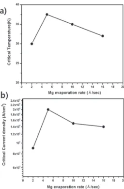
Fig. 4 shows the surface morphologies of MgB
2/carbon fibers grown by physical vapor deposition with the ~5 Å/s Mg evaporation rate, where a very dense microstructure without and cracks or voids can be seen. Fig. 5 shows the critical temperature and critical current density dependence on the Mg evaporation rate. The highest J
cresult was calculated to be ~ 2 × 10
4A/cm
2at 20 K, 0 T. Since the size of the deposited MgB
2/carbon fiber was very small and
Fig. 4. Surface morphologies of MgB
2/carbon fibers deposited at 600 C/30min by co-evaporation with the ~5 Å/s Mg evaporation rate. a) longitudinal image, b) enlarged surface image at x20K.
short, the superconducting properties measured with PPMS(Physical Property Measurement System, Quantum Design Co.) were subjected to the large error range due to the small volume fraction of MgB
2.
The critical temperature ranged from the highest ~37.5 K to the lowest ~25 K in the samples with ~5 Å/s Mg evaporation rate and with ~2 Å/s Mg evaporation rate, respectively. Fig. 6 shows the resistivity vs. temperature curves of MgB
2/carbon fibers formed at ~5 Å/s Mg evaporation rate. When the Mg evaporation rate exceeded an optimum value such as ~5 Å/s in this study, the excess Mg did not reacted with B to form MgB
2, rather it just deposited on the surface layer as the metallic impurity phase as can be seen in Fig. 2a) and 2b). T
cand J
cof the fiber in Fig.5 showed the maximum value at ~5 Å/s Mg evaporation rate and decreased with the higher Mg evaporation rate. The microstructural difference can be seen clearly in the insets of Fig.3 a) and c), which implies that the crystalline nature such as orientation, grain size, impurity phases such as un-reacted Mg affect the superconducting properties.
4. CONCLUSION
We have synthesized core-shell structured MgB
2/carbon
fibers using physical vapor deposition method on the
carbon fiber. Mg vapor pressure was one of the critical
factors to form the stoichiometric MgB
2film and the Mg
Influence of Mg Vapor Pressure on the MgB2/Carbon Fiber Fabricated by Physical Vapor Deposition method
Fig. 5. The dependence of critical temperature and critical current density on the Mg evaporation rate.
Fig. 6. Resistivity vs. temperature curves of the grown MgB
2/carbon fibers with the ~5 Å/s Mg evaporation rate.
flux was controlled by the funnel-like guide and the Mg evaporation temperature. The morphology and the crystallinity of MgB
2/carbon fiber were quite different depending on the Mg vapor pressure with the Mg evaporation rate.
Although very dense MgB
2film deposition on the carbon fiber has been demonstrated, the size of core-shell structured MgB
2/carbon fibers was too small to measure the transport I
cvalue. All the superconducting properties were measured by PPMS. The highest T
cwas ~37.5 K with the ~5 Å/s Mg evaporation rate and the corresponding J
cwas calculated as ~ 2×10
4A/cm
2at 20K, 0T. Further experiments are under progress to obtain long enough core-shell structured MgB
2/carbon fibers to measure the reliable superconducting properties including transport I
cand the crystallographic growth behavior of the MgB
2grain.
ACKNOWLEDGMENT
This work was supported by Basic Science Research Program through the National Research Foundation of Korea(NRF) funded by the Ministry of Education, Science and Technology(2010-0011931) and partly by the 2
ndstage of BK21 program.
REFERENCES
[1] I. Felner, “Absence of superconductivity in BeB2,” Physica C, vol.
353, pp. 11-13, 2001.
[2] D.P. Young, P.W. Adams, J.Y. Chan, F.R. Fronczek,
“Superconducting properties of BeB2.75,” Physical review B, vol. 65, No.18, pp. 180518, 2002.
[3] V.A. Gasparov, N.S. Sidorov, I.I. Zver’kova, M.P. Kulakov,
“Electron Transport in Diborides: Observation of Superconductivity in ZrB2 ,” JETP Letters, vol. 73, pp. 532-535, 2001.
[4] X.X. Xi, A.V. Pogrebnyakov, S.Y. Xu, K. Chen, Y. Cui, E.C. Maertz, C.G. Zhuang, Q. Li, D.R. Lamborn, J.M. Redwing, Z.K. Liu, A.
Soukiassian, D.G. Schlom, X.J. Weng, E.C. Dickey, Y.B. Chen, W.
Tian, X.Q. Pan, S.A. Cybart, R.C. Dynes, “MgB2 thin films by hybrid physical–chemical vapor deposition,” Physica C, vol. 456, pp. 22-37, 2007.
[5] Y. Harada, T. Takahashi, H. Iriuda, M. Kuroha, Y. Nakanishi, M.
Yoshizawa, “Optimization of co-evaporation conditions of as-grown MgB2 thin films by molecular beam epitaxy,” Physica C, vol.
426-431, pp. 1453-1458, 2005.
[6] B.H. Moeckly, W.S. Ruby, “Growth of high-quality large-area MgB2
thin films by reactive evaporation,” Supercond. Sci. Technol., Vol. 19, pp. L21-L24, 2006.
[7] Y. Harada, M. Uduka, Y. Nakanishi, N. Yoshimoto, M. Yoshizawa,
“Synthesis of as-grown superconducting MgB2 thin films by molecular beam epitaxy in UHV conditions,” Physica C, vol.
412-414, pp. 1383-1386, 2004.
[8] S. Yata, G. Shimizu, Y. Yamada, S. Kubo, A. Matsushita,
“Superconducting properties of B on Mg bilayer films sequentially deposited at low substrate temperatures,” Physica C, vol. 388-389, pp. 155-156, 2003.
[9] W.N. Kang, H.-J. Kim, E.-M. Choi, C.U. Jung, S.-I. Lee, “MgB2
superconducting thin films with a transition temperature of 39 kelvin,” Science vol. 292, pp. 1521-1523, 2001.
[10] S.D. Bu, D.M. Kim, J.H. Choi, J. Giencke, E.E. Hellstrom, D.C.
Larbalestier, S. Patnaik, L. Cooley, C.B. Eom, J. Lettieri, D.G.
Schlom, W. Tian, X.Q. Pan, “Synthesis and properties of c-axis oriented epitaxial MgB2 thin films,” Appl. Phys. Lett., Vol. 81, pp.
1851, 2002.
8
[11] C. Ferdeghini, V. Ferrando, G. Grassano, W. Ramadan, E. Bellingeri, V. Braccini, D. Marre`, M. Putti, P. Manfrinetti, A. Palenzona, F.
Borgatti, R. Felici, C. Aruta, “Anisotropy in c-oriented MgB2 thin films grown by pulsed laser deposition,” Physica C, vol. 378–381, pp. 56-60, 2002.
[12] Z.K. Liu, D.G. Schlom, Q. Li, X.X. Xi, “Thermodynamics of the Mg-B system: Implications for the deposition of MgB2 thin films, ” Appl. Phys. Lett,. Vol. 78, pp. 3678-3680, 2001.
[13] Y.J. Lim, S.C. Park, J.K. Chung, T.K. Lee, K.J. Song, C.J. Kim,
“Synthesis of the superconducting MgB2 film on the W-wire by co-evaporation method,” Physica C, vol. 470, p. p1442-1445, 2010.
[14] N.M. Hwang and D.Y. Kim, “Charged clusters in thin film growth,”
Intl. Mater. Rev., vol.49, pp. 171-190, 2004.
[15] S.C. Park, J.-K, Chung, S.G. Kang, K.J. Song, C.-J. Kim, C.J. Kim,
“Fabrication of MgB2 thin films on r-Al2O3 substrates by rf sputtering and thermal evaporation,” Physica C, vol. 468, pp.
1879-1883, 2008.