Introduction
Three-dimensional (3D) facial computed tomography (CT) is often performed on facial asymmetry patients who need orthognathic surgery because the technique provides
accurate linear and angular measurements with no image superimposition and magnification, which are invariably present in two-dimensional (2D) radiographs. Usually, the first step in a 3DCT evaluation involves establishing three orthogonal reference planes: horizontal (HRP), midsagittal (MRP), and coronal (CRP). The eventual locations (x, y, z) of the landmarks are determined from these planes.1-10The vertical positions of the landmarks are determined from the HRP, and the horizontal positions from the MRP. Because the frontal profile of the face matters the most in the evalua-
Deviation of landmarks in accordance with methods of establishing reference planes in three-dimensional facial CT evaluation
Kaeng Won Yoon1, Suk-Ja Yoon2,*, Byung-Cheol Kang2, Young-Hee Kim3, Min Suk Kook4, Jae-Seo Lee2, Juan Martin Palomo5
1School of Dentistry, Dental Science Research Institute, Chonnam National University, Gwangju, Korea
2Department of Oral and Maxillofacial Radiology, School of Dentistry, Dental Science Research Institute, Chonnam National University, Gwangju, Korea
3Department of Oral and Maxillofacial Radiology, Hallym University Sacred Heart Hospital, Anyang, Korea
4Department of Oral and Maxillofacial Surgery, School of Dentistry, Dental Science Research Institute, Chonnam National University, Gwangju, Korea
5Department of Orthodontics, School of Dental Medicine, Case Western Reserve University, Cleveland, OH, USA
ABSTRACT
Purpose: This study aimed to investigate the deviation of landmarks from horizontal or midsagittal reference planes according to the methods of establishing reference planes.
Materials and Methods: Computed tomography (CT) scans of 18 patients who received orthodontic and orthognath- ic surgical treatment were reviewed. Each CT scan was reconstructed by three methods for establishing three orthog- onal reference planes (namely, the horizontal, midsagittal, and coronal reference planes). The horizontal (bilateral porions and bilateral orbitales) and midsagittal (crista galli, nasion, prechiasmatic point, opisthion, and anterior nasal spine) landmarks were identified on each CT scan. Vertical deviation of the horizontal landmarks and horizontal deviation of the midsagittal landmarks were measured.
Results: The porion and orbitale, which were not involved in establishing the horizontal reference plane, were found to deviate vertically from the horizontal reference plane in the three methods. The midsagittal landmarks, which were not used for the midsagittal reference plane, deviated horizontally from the midsagittal reference plane in the three methods.
Conclusion: In a three-dimensional facial analysis, the vertical and horizontal deviations of the landmarks from the horizontal and midsagittal reference planes could vary depending on the methods of establishing reference planes.
(Imaging Sci Dent 2014; 44: 207-12)
KEY WORDS: Tomography, X-Ray Computed; Facial Asymmetry; Orthognathic Surgery
Received September 23, 2013; Revised June 9, 2014; Accepted June 20, 2014
*Correspondence to : Prof. Suk-Ja Yoon
Department of Oral and Maxillofacial Radiology, School of Dentistry, Chonnam National University, 77 Yongbong-ro, Bukgu, Gwangju 500-757, Korea
Tel) 82-62-530-5680, Fax) 82-62-530-5689, E-mail) [email protected]
Copyright ⓒ 2014 by Korean Academy of Oral and Maxillofacial Radiology
This is an Open Access article distributed under the terms of the Creative Commons Attribution Non-Commercial License (http://creativecommons.org/licenses/by-nc/3.0) which permits unrestricted non-commercial use, distribution, and reproduction in any medium, provided the original work is properly cited.
Imaging Science in Dentistry∙pISSN 2233-7822 eISSN 2233-7830
tion of facial asymmetry, the processes of establishing the HRP and MRP are very important.
Various methods for establishing reference planes have been introduced depending on whether the HRP or the MRP is first established and depending on the landmarks used for the reference planes. The reference plane established second might be influenced by the reference plane estab- lished first. The crista galli (CR), porion (Po), and orbitale (Or) have been traditionally used as reference lines in 2D radiographic analyses,11,12and they are also used as refer- ence planes in 3D CT analyses. The prechiasmatic groove (P) or opisthion (Op) are additionally used for establishing reference planes in 3D CT.3-10The landmark coordinates and facial analysis results might differ depending on the method of establishing the reference planes. Kim et al13 reported that different methods for establishing the MRP have yielded different deviations of the anterior nasal spine (ANS) and the genial tubercle from the MRP.
Thus, it can be presumed that the landmarks that can be used for the HRP and MRP in a 3D CT face analysis might deviate vertically or horizontally depending on the method of establishing the reference planes. This study aimed to investigate the deviation of landmarks that can be used for the HRP and MRP according to the methods of estab- lishing the reference planes. To this end, each subject was analyzed using three different methods.
Materials and Methods
CT scans were selected from orthodontic patients who received orthodontic and orthognathic surgical treatments between 2002 and 2008 for improving facial asymmetry.
Eighteen orthodontic patients were included in this study (10 males and 8 females; mean patient age: 33.6 years;
patient age range: 18.1-39.1 years). The CT scan of each patient was analyzed with three different methods of estab- lishing reference planes.
CT scans and 3D reconstruction of CT scans
CT scans were obtained using a spiral CT scanner (Light Speed QX/I, GE Medical Systems, Milwaukee, WI) with the following specifications: 512×512 matrix, 120 kV, 200 mA, and gantry angle of 0。. The axial image thickness was 2.5 mm, table speed was 3 mm/s, and scanning time was 0.8 s. Digital imaging and communications in medicine (DICOM) images were created with a slice thickness of 1.0 mm. The acquired DICOM data were input into a per- sonal computer. Using CT data, we reconstructed the 3D
images with Vworks 4.0++Vsurgery (Cybermed, Seoul, Korea). A surface-rendered model was prepared, and the landmarks were defined on the surface-rendered model in Vworks 4.0 by an oral and maxillofacial radiologist.
A multiplanar reformatted image, volumetric model, and surface-rendered model of a CT scan, which were com- pletely interfaced with each other using software, were constructed on Vworks 4.0. The landmarks were defined on the volumetric model with the guidance of the multi- planar reformatted image.
Three different methods for establishing reference planes
M1: The HRP (xy plane) was first established with the right Po (PoR), left Po (PoL), and left Or (OrL). Then, the MRP (yz plane) was formed perpendicular to the HRP and passing through the Cg and P. The CRP (xz plane), passing through the Op, was perpendicular to both the MRP and the HRP.3
M2: MRP (yz plane) was first established with the Cg, ANS, and Op.7-9Then, the HRP (xy plane) was formed per- pendicular to the MRP and passing through the right Or (OrR) and PoL. The CRP (xz plane), passing through the Op, was perpendicular to both the MRP and the HRP.
M3: The HRP (xy plane) was first established with the PoL, OrR, and OrL.10Then, the MRP (yz plane) was for- med perpendicular to the HRP and passing through the
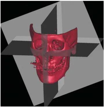
Fig. 1.Three orthogonal planes are established for each subject.
nasion (Na) and Op. The CRP (xz plane), passing through the Op, was perpendicular to both the MRP and the HRP.
Obtaining coordinates
All image data and surface-rendered models were trans-
ferred to the Vsurgery program on which lzl was obtained for the horizontal landmarks (PoR, PoL, OrR, and OrL) for evaluating vertical deviation and lxl was obtained for the midsagittal landmarks (Cg, Na, P, Op, and ANS) for eval- uating horizontal deviation. lxl is the distance from the
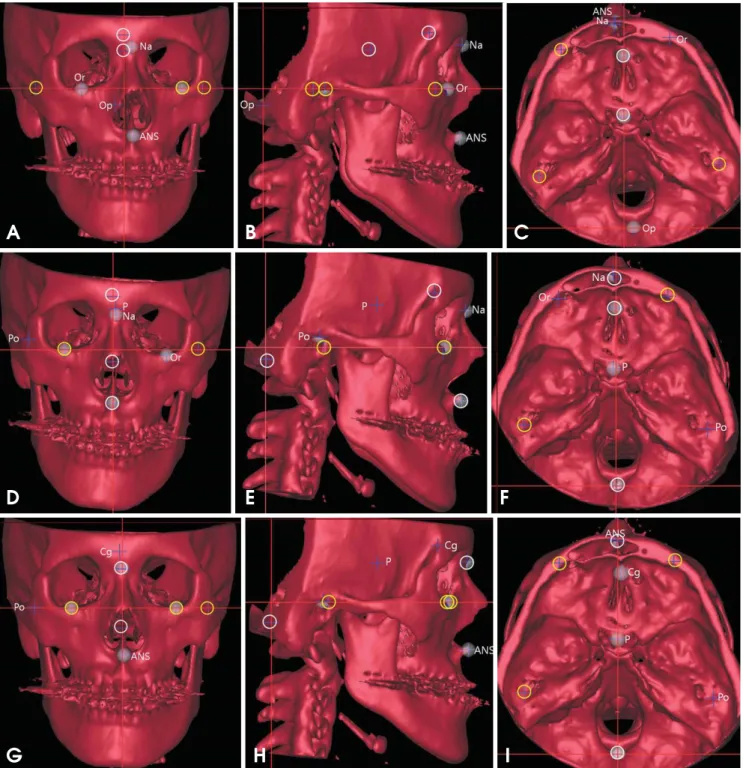
Fig. 2.One subject is analyzed by three methods (A-C: M1; D-F: M2; and G-I: M3). The landmarks used for the HRP are marked as yellow circles; those for the MRP as white circles. The landmarks that are not involved in establishing the HRP and MRP are named. A-C:
The Na, Op, and ANS deviated horizontally from the MRP. D-F: The P and Na deviated horizontally from the MRP, and the Po and Or vertically from the HRP. G-I: The Cg and ANS deviated horizontally from the MRP.
A B C
D E F
G H I
MRP, and lzl is the distance from the HRP (Fig. 1). The three different methods (M1, M2, and M3) of establishing reference planes resulted in different landmark coordinates.
Figure 2 shows an example of the results of using three different methods for determining the reference planes of one subject (Fig. 2). The landmarks and the reference planes
for each method are summarized in Tables 1 and 2, respec- tively.
Table 1.Landmarks used in this study.
Landmarks Definition
Horizontal landmarks PoR Right porion Highest midpoint of roof of right external auditory meatus PoL Left porion Highest midpoint of roof of left external auditory meatus OrR Right orbitale Lowest point on right infraorbital margin of the orbit OrL Left orbitale Lowest point on left infraorbital margin of the orbit Midsagittal landmarks Cg Crista galli Most superior point of crista galli of ethmoid bone
Na Nasion Most posterior point on curvature between frontal bone and nasal bone in midsagittal plane
P Prechiasmatic groove Vertical and transverse midpoint of prechiasmatic groove Op Opisthion Most posterior point on posterior margin of foramen magnum ANS Anterior nasal spine Most anterior point of nasal floor
Table 2.Three different methods for establishing orthogonal reference planes for this study.
Method Reference plane Establishing orthogonal reference planes
M1 HRP Passing through PoR-PoL-OrL
MRP Perpendicular to HRP, passing through Cg-P
CRP Perpendicular to HRP and MRP, passing through Op
M2 MRP Passing through Cg-ANS-Op
HRP Perpendicular to MRP, passing through OrR-PoL
CRP Perpendicular to MRP and HRP, passing through Op
M3 HRP Passing through PoL-OrR-OrL
MRP Perpendicular to HRP, passing through Na-Op
CRP Perpendicular to HRP and MRP, passing through Op
HRP: Horizontal Reference Plane, MRP: Midsagittal Reference Plane, CRP: Coronal Reference Plane
Table 3.Vertical deviation (|z|) of horizontal landmarks used in this study (unit: mm)
Horizontal Vertical
M1 M2 M3
landmark deviation (|z|)
PoR Mean±SD - 2.46±1.90 1.76±1.22
Max - 7.23 4.17
Min - 2.55 0.39
PoL Mean±SD - - -
Max - - -
Min - - -
OrR Mean±SD 0.98±0.61 - -
Max 2.25 - -
Min 0.11 - -
OrL Mean±SD - 1.54±1.10 -
Max - 3.63 -
Min - 1.60 -
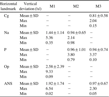
Table 4.Horizontal deviation (|x|) of midsagittal landmarks used in this study (unit: mm)
Horizontal Vertical
M1 M2 M3
landmark deviation (|x|)
Cg Mean±SD - - 0.81±0.58
Max - - 2.04
Min - - 0.15
Na Mean±SD 1.44±1.14 0.94±0.65 -
Max 5.36 2.14 -
Min 0.35 0.98 -
P Mean±SD - 0.96±1.01 0.94±0.74
Max - 3.80 3.37
Min - 0.79 0.10
Op Mean±SD 2.58±2.39 - -
Max 9.33 - -
Min 0.09 - -
ANS Mean±SD 1.92±1.74 - 0.97±0.67
Max 6.54 - 2.30
Min 0.02 - 0.05
Results
The vertical deviation (lzl) of the horizontal landmarks (PoR, PoL, OrR, and OrL) and the horizontal deviation (lxl) of the midsagittal landmarks (Cg, Na, P, Op, and ANS) were measured. The Po and Or, which were not considered when establishing the HRP, were not in the plane when using M1, M2, and M3. In M1, the PoR, PoL, and OrL were used for the HRP (lzl==0 mm), whereas the OrR deviated either up- ward or downward (lzl==0.98±0.61 mm). In M2, the PoR and OrL, which were not used for the HRP, deviated either upward or downward (lzl==2.46±1.90 mm, lzl==1.54±1.10 mm). In M3, the PoR, which was not used for the HRP, deviated either upward or downward (lzl==1.76±1.22 mm).
In M1 and M2, either inferior orbital rim deviated from the HRP. Cg was used for establishing the MRP in M1 and M2, and its lxl was 0 mm. In M3, the lxl of the Cg was 0.81
±0.58 mm, and the Cg deviated toward either side. In M1 and M2, the lxl of the Na, which was not used for the MRP, was 1.44±1.14 mm in M1 and 0.94±0.65 mm in M2. The lxl of the P was 0.96±1.01 mm in M2 and 0.94±0.74 mm in M3. The lxl of the Op was 2.58±2.39 mm in M1. The lxl of the ANS was 1.92±1.74 mm in M1 and 0.97±0.67 mm in M3 (Tables 3 and 4).
Discussion
The key to a successful treatment of facial asymmetry is adequate analysis and diagnosis. Various methods of estab- lishing reference planes in 3DCT have been introduced by many researchers.1-10Some researchers have analyzed facial asymmetry using 3DCT by first establishing three orthogonal reference planes (HRP, MRP, and CRP), which allows for asymmetry measurement as well as planning for subsequent surgery. The rectangular coordinates (x, y, z) of the landmarks are determined from the orthogonal refer- ence planes.2-5,7The frontal profile is the most important in facial asymmetry analysis; therefore, among the three reference planes, the HRP and the MRP are of critical im- portance. Therefore, this study aimed to evaluate deviations of the landmarks used for establishing the HRP and the MRP.
The Po and Or are used to form the Frankfort line on cephalometric radiographs and to form the HRP on 3D CT.
Among the four horizontal landmarks, that is, the PoR, PoL, OrR, and OrL, two or three are selected to make the HRP: the bilateral Po and unilateral Or, or unilateral Po and unilateral Or.3-9The resulting faces showed a deviation of the other Or, or a deviation of the unilateral inferior or-
bital rim. The Or deviated by up to 3.63 mm in this study (Table 3, Fig. 2). Pelo et al14 reported that in their research using 10 subjects, no subject had a bilateral Po and bilat- eral Or on one HRP. It might not be possible to have the four horizontal landmarks located on the same plane. If the clinician prefers to have the bilateral Or parallel to the floor, the bilateral Or should be selected for the HRP, as in M3.10It is suggested that the clinician should first deter- mine whether the bilateral Or should be parallel to the floor.
Cg has been most commonly used for the mid-facial line in cephalometric radiographs11,12and for the MRP in 3DCT, as in M1 and M2.3,6-9 Meanwhile, in M3, the Cg showed a lateral deviation (lxl==0.81±0.58 mm). The Na can be also used for the MRP.1,2,4,5,10In this study, the Na deviated in M1 and M2 (lxl==1.44±1.14 mm in M1; lxl== 0.94±0.65 mm in M2), where the Na was not used for the MRP. The deviation of the Na was up to 5.36 mm. These results can possibly be ascribed to the fact that the Cg is located inside the cranium and Na is located outside. When the Cg is used for the MRP, it is possible that the resulting face is deviated on either side (Table 4, Fig. 2).
The P or Op is used for the MRP.3-10The P is a landmark on the anterior cranial fossa, and the Op is located in the most posterior position to the foramen magnum. The Op is one of the most reproducible landmarks in a 3DCT an- alysis.15-17When the Op was used for the MRP, as in M2 and M3, the P deviated by up to 3.80 mm. Meanwhile, when the P was used for the MRP, as in M1, the Op devi- ated by up to 9.33 mm, which results in considerable faci- al deviation(Table 4, Fig. 2).
Anterior and posterior landmarks are needed for the MRP. Most anterior and posterior landmarks can be used to construct a better MRP that divides a head into two halves more precisely. Because the Na is located further anterior than the Cg and the Op is located further posterior than the P, the Na and Op can be used to construct a better MRP than that of the Cg and P.
The ANS is often used for forming the MRP.7-9In this study, the ANS deviated laterally in M1 and M3 (lxl==1.92
±1.74 mm in M1; lxl==0.97±0.67 mm in M3). The ANS, a landmark on the maxilla, can deviate if the maxilla has a deviation. Trpkova et al18stated that the ANS is not suit- able for establishing the mid-facial line on 2D cephalome- tric radiographs. Therefore, the ANS might not be suitable for generating the MRP in 3DCT either.
Facial asymmetry can be assessed differently depending on the mid-facial lines in 2D radiographs.18,19Kim et al13 showed that a facial asymmetry analysis with 3DCT can
be also influenced by the methods of establishing the ref- erence planes, as is the case with reference lines in 2D ra- diographs. In addition, we showed that the landmarks used for HRP and MRP might be influenced by the methods of establishing reference planes and could deviate from the planes.
Facial asymmetry is not only about bone but also about soft tissue. Facial asymmetry in radiographs might appear different from that on real faces. In this study, we assessed only bony landmarks. Further study is needed with soft- tissue landmarks.
In conclusion, we evaluated the deviation of the land- marks used for establishing the HRP and the MRP in accor- dance with the methods of establishing the reference planes.
There was a vertical or horizontal deviation of the land- marks depending on the methods used for establishing the reference planes. The clinician should be alert to establish- ing the reference planes in order to avoid an undesirable facial deviation. It is suggested that a face be evaluated by establishing reference planes using not only one method but two or more methods, which might be helpful for im- proving the accuracy of a facial analysis.
References
1. Katsumata A, Fujishita M, Maeda M, Ariji Y, Ariji E, Langlais RP. 3D-CT evaluation of facial asymmetry. Oral Surg Oral Med Oral Pathol Oral Radiol Endod 2005; 99: 212-20.
2. Maeda M, Katsumata A, Ariji Y, Muramatsu A, Yoshida K, Goto S, et al. 3D-CT evaluation of facial asymmetry in patients with maxillofacial deformities. Oral Surg Oral Med Oral Pathol Oral Radiol Endod 2006; 102: 382-90.
3. Kwon TG, Park HS, Ryoo HM, Lee SH. A comparison of cra- niofacial morphology in patients with and without facial asym- metry-a three-dimensional analysis with computed tomogra- phy. Int J Oral Maxillofac Surg 2006; 35: 43-8.
4. Park SH, Yu HS, Kim KD, Lee KJ, Baik HS. A proposal for a new analysis of craniofacial morphology by 3-dimensional computed tomography. Am J Orthod Dentofacial Orthop 2006;
129: 600.e23-34.
5. Yoon SJ, Lim HJ, Kang BC, Hwang HS. Three dimensional CT analysis of facial asymmetry. Korean J Oral Maxillofac Radiol 2007; 37: 45-52.
6. Baek SH, Cho IS, Chang YI, Kim MJ. Skeletodental factors affecting chin point deviation in female patients with class III malocclusion and facial asymmetry: a three-dimensional analy- sis using computed tomography. Oral Surg Oral Med Oral Pa-
thol Oral Radiol Endod 2007; 104: 628-39.
7. Yoon SJ, Wang RF, Hwang HS, Kang BC, Lee JS, Palomo JM.
Application of spherical coordinate system to facial asymmetry analysis in mandibular prognathism patients. Imaging Sci Dent 2011; 41: 95-100.
8. Hwang HS, Hwang CH, Lee KH, Kang BC. Maxillofacial 3- dimensional image analysis for the diagnosis of facial asymme- try. Am J Orthod Dentofacial Orthop 2006; 130: 779-85.
9. Kim EJ, Palomo JM, Kim SS, Lim HJ, Lee KM, Hwang HS.
Maxillofacial characteristics affecting chin deviation between mandibular retrusion and prognathism patients. Angle Orthod 2011; 81: 988-93.
10. Baek C, Paeng JY, Lee JS, Hong J. Morphologic evaluation and classification of facial asymmetry using 3-dimensional computed tomography. J Oral Maxillofac Surg 2012; 70: 1161- 9.
11. Grumons DC, Kappeyne van de Coppello MA. A frontal asym- metry analysis. J Clin Orthod 1987; 21: 448-65.
12. Haraguchi S, Takada K, Yasuda Y. Facial asymmetry in sub- jects with skeletal Class III deformity. Angle Orthod 2002; 72:
28-35.
13. Kim TY, Baik JS, Park JY, Chae HS, Huh KH, Choi SC. De- termination of midsagittal plane for evaluation of facial asym- metry using three-dimensional computed tomography. Imaging Sci Dent 2011; 41: 79-84.
14. Pelo S, Deli R, Correra P, Boniello R, Gasparini G, Moro A.
Evaluation of 2 different reference planes used for the study of asymmetric facial malformations. J Craniofac Surg 2009; 20:
41-5.
15. Farman AG, Scarfe WC. Development of imaging selection criteria and procedures should precede cephalometric assess- ment with cone-beam computed tomography. Am J Orthod Dentofacial Orthop 2006; 130: 257-65.
16. Muramatsu A, Kimura M, Nawa H, Yoshida K, Maeda M, Ka- tsumata A, et al. Reproducibility of maxillofacial anatomic landmarks on 3-dimensional computed tomographic images determined with the 95% confidence ellipse method. Angle Orthod 2008; 78: 396-402.
17. Ramírez-Sotelo LR, Almeida S, Ambrosano GM, Bóscolo F.
Validity and reproducibility of cephalometric measurements performed in full and hemifacial reconstructions derived from cone beam computed tomography. Angle Orthod 2012; 82:
827-32.
18. Trpkova B, Prasad NG, Lam EW, Raboud D, Glover KE, Major PW. Assessment of facial asymmetries from posteroanterior cephalograms: validity of reference lines. Am J Orthod Dento- facial Orthop 2003; 123: 512-20.
19. Ferguson JW. Cephalometric interpretation and assessment of facial asymmetry secondary to congenital torticollis. The signi- ficance of cranial base reference lines. Int J Oral Maxillofac Surg 1993; 22: 7-10.