Three-dimensional evaluation of the correlation
between lip canting and craniofacial planes
Objective: This study aimed to analyze the correlation of horizontal and sagittal planes used in two-dimensional diagnosis with lip canting by using three-dimensional (3D) analysis. Methods: Fifty-two patients (25 men, 27 women; average age: 24 years) undergoing treatment for dentofacial deformity were enrolled. Computed tomography images were acquired, and digital imaging and communication in medicine files were reconstructed into a 3D virtual model wherein horizontal and sagittal craniofacial planes were measured. Subsequently, the correlations of lip canting with these horizontal and sagittal planes were investigated. Results: The mandibular symmetry plane, the occlusal plane, Camper’s plane, the mandibular plane, Broadbent’s plane, and the nasal axis plane were correlated with the amount of lip canting (Pearson’s correlation coefficients: 0.761, 0.648, 0.556, 0.526, 0.438, and 0.406, respectively). Planes associated with the lower part of the face showed the strongest correlations; the strength of the correlations decreased in the midfacial and cranial regions. None of the planes showed statistically significant differences between patients with clinical lip canting (> 3°) and those without prominent lip canting. Conclusions: The findings of this study suggest that lip canting is strongly correlated with the mandibular symmetry plane, which includes menton deviation. This finding may have clinical implications with regard to the treatment of patients requiring correction of lip canting. Further studies are necessary for evaluating changes in lip canting after orthognathic surgery.
[Korean J Orthod 2020;50(4):258-267]
Key words: Three-dimensional cephalometrics, Three-dimensional diagnosis, Lip canting, Facial asymmetry
Jun-Young Kima
Hee-Keun Parkb
Seung-Woo Shina
Jin Hoo Parka
Hwi-Dong Junga
Young-Soo Junga
aDepartment of Oral and Maxillofacial
Surgery, Oral Science Research Center, Yonsei University College of Dentistry, Seoul, Korea
bPrivate Practice, Uijeongbu, Korea
Received December 10, 2019; Revised March 10, 2020; Accepted March 27, 2020.
Corresponding author: Young-Soo Jung.
Professor, Department of Oral and Maxillofacial Surgery, Yonsei University College of Dentistry, 50-1 Yonsei-ro, Seodaemun-gu, Seoul 03722, Korea.
Tel +82-2-2228-3139 e-mail [email protected]
Jun-Young Kim and Hee-Keun Park contributed equally to this study.
How to cite this article: Kim JY, Park HK, Shin SW, Park JH, Jung HD, Jung YS. Three-dimensional evaluation of the correlation between lip canting and craniofacial planes. Korean J Orthod 2020;50:258-267.
© 2020 The Korean Association of Orthodontists.
This is an Open Access article distributed under the terms of the Creative Commons Attribution Non-Commercial License (http://creativecommons.org/licenses/by-nc/4.0) which permits unrestricted non-commercial use, distribution, and reproduction in any medium, provided the original work is properly cited.
pISSN 2234-7518 • eISSN 2005-372X https://doi.org/10.4041/kjod.2020.50.4.258
INTRODUCTION
Facial asymmetry is one of the most common condi-tions for which patients seek treatment in maxillofacial surgery departments, and it can be caused by several factors, including congenital and developmental factors.1
Asymmetry related to lip canting, which is observed caudal to the orbital region, nose, dental region, lip, and chin, is more apparent than that related to the cranium or eye.2 Asymmetries of the jaw and nose are routinely
treated by orthognathic surgery or rhinoplasty, and these surgeries provide predictable outcomes.3 However,
asymmetry may persist when occlusal plane or lip cant-ing persists.4 In many cases of dentofacial deformities
requiring orthognathic surgery, the inclination of the lip can be confirmed. Persistence of the lip canting after surgery results in reduced patient satisfaction. Therefore, lip canting and the causative factors should be consid-ered during surgical treatment planning.5
Padwa et al.6 reported that occlusal canting can be
perceived in 90% of patients if it exceeds 3°. Chu et al.7
reported that asymmetry of the oral commissure mea-suring < 3 mm and eye canting were not recognized as clinically insignificant. Lip canting is known to play an important role in the attractiveness of the face,8
accord-ing to Song et al.,9 55.3% adults without facial
deformi-ties exhibit lip canting.
Lip canting is a line connecting both sides of the lip commissure when observed from the front. It is affected by the adjacent hard and soft tissues and caused by a difference in height between the left and right corners.10
Lip canting is an important parameter in orthodontic treatment because many people are aware of the as-sociated asymmetry and occasionally exhibit residual lip canting after conventional bimaxillary orthognathic surgery. Most studies related to lip canting have been based on the clinical photographs and cephalograms of patients. Although this method is inexpensive11 and
easy,12 inherent limitations of two-dimensional (2D)
im-ages result in errors during overlapping of the skeletal
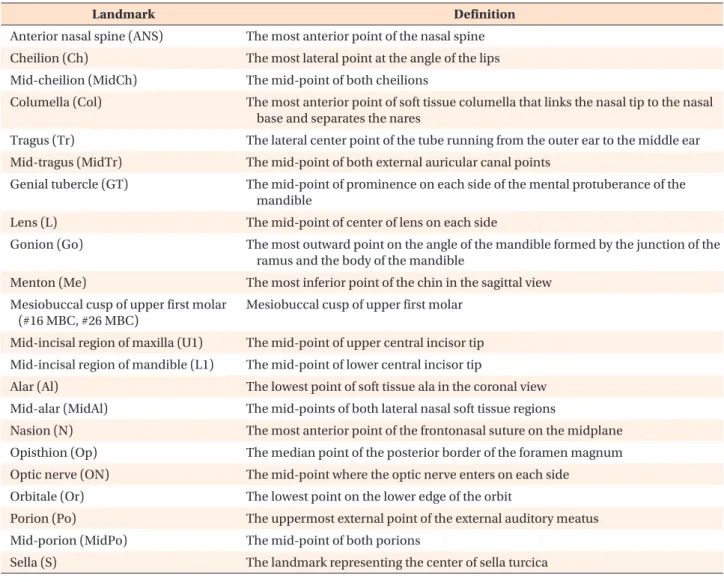
Table 1. Anatomical landmarks used in the present study and their definitions
Landmark Definition
Anterior nasal spine (ANS) The most anterior point of the nasal spine
Cheilion (Ch) The most lateral point at the angle of the lips
Mid-cheilion (MidCh) The mid-point of both cheilions
Columella (Col) The most anterior point of soft tissue columella that links the nasal tip to the nasal
base and separates the nares
Tragus (Tr) The lateral center point of the tube running from the outer ear to the middle ear
Mid-tragus (MidTr) The mid-point of both external auricular canal points
Genial tubercle (GT) The mid-point of prominence on each side of the mental protuberance of the
mandible
Lens (L) The mid-point of center of lens on each side
Gonion (Go) The most outward point on the angle of the mandible formed by the junction of the
ramus and the body of the mandible
Menton (Me) The most inferior point of the chin in the sagittal view
Mesiobuccal cusp of upper first molar (#16 MBC, #26 MBC)
Mesiobuccal cusp of upper first molar Mid-incisal region of maxilla (U1) The mid-point of upper central incisor tip Mid-incisal region of mandible (L1) The mid-point of lower central incisor tip
Alar (Al) The lowest point of soft tissue ala in the coronal view
Mid-alar (MidAl) The mid-points of both lateral nasal soft tissue regions
Nasion (N) The most anterior point of the frontonasal suture on the midplane
Opisthion (Op) The median point of the posterior border of the foramen magnum
Optic nerve (ON) The mid-point where the optic nerve enters on each side
Orbitale (Or) The lowest point on the lower edge of the orbit
Porion (Po) The uppermost external point of the external auditory meatus
Mid-porion (MidPo) The mid-point of both porions
structures.13 In contrast, three-dimensional (3D) imaging
using computed tomography (CT) is an easy technique for quantifying the desired anatomical structures,13 with
few errors caused by enlargement, distortion, and nest-ing.14,15 This 3D simulation has better predictability and
can be used to set up a surgical plan, which is very help-ful for surgery to correct asymmetric surgery.16 However,
research predicting lip soft tissue changes using 3D analysis is lacking.5
Accordingly, the purpose of this study was to analyze the correlation of horizontal and sagittal planes used in 2D diagnosis with lip canting by using 3D analysis. On the basis of the results, we investigated planes that showed strong correlations with lip canting in order to determine the planes that should be prioritized for the improvement of lip canting during orthognathic surgery.
MATERIALS AND METHODS
Patients and data sourcesThis study was conducted according to the tenets of the Declaration of Helsinki regarding medical proto-col and ethics and was approved by the Ethical Review Board of Yonsei University Dental Hospital (Institutional Review Board No. 2-2013-0004). The requirement for informed consent was waived because of the retrospec-tive nature of the study.
From January 2010 to January 2018, we conducted a retrospective study of patients with Class III malocclu-sion who underwent CT and clinical examinations for the diagnosis of maxillofacial deformities. The
exclu-sion criteria were as follows: 1) congenital deformities, including cleft lip and palate; 2) unidentified occlusal plane due to the loss of multiple teeth; 3) previous his-tory of facial and jaw surgeries; 4) no record of frontal photographs or CT data, because of which the degree of lip canting could not be confirmed; and 5) presence of conditions causing severe ectopic positioning of the bilateral orbitale and porion (for example, hemifacial microsomia), because of which the Frankfort horizontal plane could not be reliably identified.
Data collection Acquisition of CT scans
CT scans were acquired using a high-speed Advantage CT system (GE Medical System, Milwaukee, WI, USA). For all patients, images were scanned using the high-resolution bone algorithm under the following condi-tions: 200 mA; 120 kV; scanning time, 1 second; thick-ness, 1 mm; and 512 × 512 pixels.
Reorientation of CT scans
Three-dimensional planning software (SimPlant Pro Crystal, ver. 2011; Materialize Dental Co., Leuven, Bel-gium) was used for analysis of the facial bones and soft tissues. 3D reconstruction of the craniofacial structures was performed using the CT scans. For reconstruction of hard tissues such as the bone and teeth, a threshold was set from 662 for the cortical bone to 3,071 for the enamel. Furthermore, for soft reconstruction, a threshold ranging from –200 to 200 was set for the creation of a
Nasion Nasion Sella Sella Optic nerve Lt Optic nerve Lt Porion Lt Porion Lt Orbitale Lt Orbitale Lt Opisthion Opisthion ANS ANS Mid incisor U1 Mid incisor U1 #26 MBC #26 MBC Gonion Lt Gonion Lt Mid incisior L1 Mid incisior L1 #16 MBC #16 MBC Gonion Rt Gonion Rt Genial tubercle Genial tubercle Menton Menton Orbitale Rt Orbitale Rt Porion Rt Porion Rt Optic nerve Rt Optic nerve Rt A Lens Lt Lens Lt Lens Rt Lens Rt Alar Rt
Alar Rt Alar LtAlar Lt Columella Columella Cheilion Lt Cheilion Lt Cheilion Rt Cheilion Rt B Figure 1. Craniofacial anatomical landmarks used for defining the craniofacial planes evaluated in the present study. A, Hard tissue landmarks. B, Soft tissue landmarks.
Rt, Right; Lt, left.
virtual 3D model.
Setting of landmarks and planes 1) Landmarks
A total of 23 landmarks were used in this study (Table 1, Figure 1): anterior nasal spine (ANS), cheilion (Ch), columella (Col), tragus (Tr), mid-tragus (MidTr), genial tubercle (GT), lens (L), gonion (Go), menton (Me), mesio-buccal cusp (MBC) of the maxillary first molars (#16 and #26), mid-cheilion (MidCh), mid-incisor of maxilla (U1), mid-incisor of mandible (L1), alar (Al), mid-alar (MidAl), nasion (N), opisthion (Op), optic nerve (ON), orbitale (Or), porion (Po), midporion (MidPo), and sella (S).
2) Reference craniofacial planes
On the basis of the landmarks, eight horizontal planes and three sagittal planes were identified. With the ex-ception of two sagittal planes that were designed for the present study, all the identified planes have been widely used in previous studies. The two sagittal planes
designed by the authors were termed the mandibular symmetry and nasal axis planes. The third sagittal plane was the mid-sagittal plane, which is the center line of the face. In addition, one coronal plane was set to mea-sure the angle between two planes; therefore, a total of 12 planes were set. The definition of each plane is given below (Table 2).
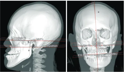
(1) Horizontal planes associated with the cranium (Figure 2)
a) Broadbent’s plane (= SN plane) b) Optical axis plane17
(2) Horizontal and sagittal planes associated with the midface (Figure 3)
a) Frankfort horizontal plane (FH plane)
b) Camper’s plane: A plane known as the Ala-tragus line18
c) His’ plane
d) Occlusal plane: A plane passing through the mid-incisal region of the maxilla and MBC of the maxillary
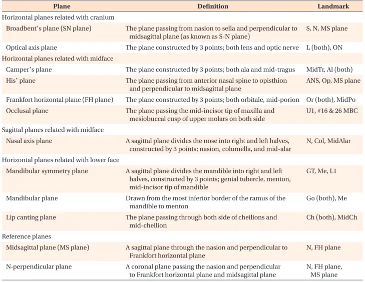
Table 2. Definitions of the craniofacial planes evaluated in the present study
Plane Definition Landmark
Horizontal planes related with cranium
Broadbent’s plane (SN plane) The plane passing from nasion to sella and perpendicular to
midsagittal plane (as known as S-N plane)
S, N, MS plane
Optical axis plane The plane constructed by 3 points; both lens and optic nerve L (both), ON
Horizontal planes related with midface
Camper’s plane The plane constructed by 3 points; both ala and mid-tragus MidTr, Al (both)
His’ plane The plane passing from anterior nasal spine to opisthion
and perpendicular to midsagittal plane
ANS, Op, MS plane Frankfort horizontal plane (FH plane) The plane constructed by 3 points; both orbitale, mid-porion Or (both), MidPo
Occlusal plane The plane passing the mid-incisor tip of maxilla and
mesiobuccal cusp of upper molars on both side
U1, #16 & 26 MBC Sagittal planes related with midface
Nasal axis plane A sagittal plane divides the nose into right and left halves,
constructed by 3 points; nasion, columella, and mid-alar
N, Col, MidAlar Horizontal planes related with lower face
Mandibular symmetry plane A sagittal plane divides the mandible into right and left
halves, constructed by 3 points; genial tubercle, menton, mid-incisor tip of mandible
GT, Me, L1
Mandibular plane Drawn from the most inferior border of the ramus of the
mandible to menton
Go (both), Me
Lip canting plane The plane passing through both side of cheilions and
mid-cheilion
Ch (both), MidCh Reference planes
Midsagittal plane (MS plane) A sagittal plane through the nasion and perpendicular to
Frankfort horizontal plane
N, FH plane
N-perpendicular plane A coronal plane passing the nasion and perpendicular
to Frankfort horizontal plane and midsagittal plane
N, FH plane, MS plane See Table 1 for definitions of each landmarks.
first molars
e) Nasal axis plane: A sagittal plane crossing the na-sion, mid-alar region, and columella while bisecting the nose
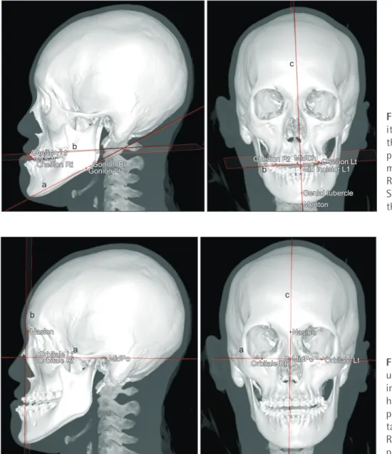
(3) Horizontal and sagittal planes associated with the lower face (Figure 4)
a) Mandibular plane b) Lip canting plane
c) Mandibular symmetry plane: A sagittal plane that confirmed the symmetry of the mandible by passing through the menton, mid-incisal region of the mandible, and genial tubercle
(4) Reference planes (Figure 5)
a) Midsagittal plane: The absolute sagittal reference plane that was considered the measurement standard for the nasal axis and mandibular symmetry planes
b) FH plane
c) N-perpendicular plane: A coronal plane for mea-suring the angle between planes in the frontal view Measurement of the angle between planes
We used the FH plane and the midsagittal plane as the absolute horizontal and absolute sagittal reference planes, respectively. The angles between the horizontal planes and the absolute horizontal reference plane (FH plane) were measured on the N-perpendicular plane. The nasal axis plane and the mandibular symmetry plane, which are sagittal planes, were measured on the N-perpendicular planes with the absolute sagittal reference plane (midsagittal plane) (Figure 6).
The smaller of the two angles was selected, and the direction of the angle was classified into clockwise (CW) and counterclockwise (CCW) directions. An angle mea-sured in the CW direction was assigned a positive value, while that measured in the CCW direction was assigned a negative value. This was done to facilitate the calcula-tion of values and ensure direccalcula-tionality and consistency of results.
To check the intraobserver reproducibility, 2 weeks after the first measurement, the same measurer reset the 23 reference points in the same virtual 3D model, recon-structed the planes to be measured, measured the angle between two planes with the same methods used for the initial measurements, and confirmed the degree of canting. Statistical analysis
Pearson’s correlation analysis was performed to
deter-Figure 2. Horizontal planes associated with the cranium (a, Broadbent’s plane = sella–nasion plane; b, optical axis plane).
Rt, Right; Lt, left; MidON, mid optic nerve.
Nasion Nasion Lens Rt Lens Rt Lens Lt Lens Lt MidON MidON Sella Sella a b
Figure 3. Horizontal and sag-ittal planes associated with the midface. a, His’ plane; b, Frankfort horizontal plane; c, Camper’s plane; d, occlusal plane; e, nasal axis plane. Rt, Right; Lt, left.
See Table 1 for definitions of the other landmarks.
Orbitale Rt Orbitale Rt Orbitale Lt Orbitale Lt ANS ANS MidPo MidPo Opisthion Opisthion a b Nasion Nasion MidTr MidTr Alar Lt Alar Lt ANS ANS Columella Columella Alar Rt Alar Rt #16 MBC
#16 MBC Mid incisor U1Mid incisor U1#26 MBC#26 MBC
c
d e
mine the correlation between lip canting and the degree of inclination of each plane. Simple regression analysis was used to study the linear relationship between lip canting and each plane. Furthermore, depending on whether the angle between the lip canting plane and FH plane exceeded 3°, which is the criterion for clinical lip canting, we divided the patients into clinically prominent (20 patients) and not prominent (32 patients) groups and determined whether between-group differences in craniofacial plane inclinations were statistically signifi-cant.19 We performed a t-test for comparative analysis.
Collation and calculation of all data were performed using Microsoft Excel 2007 (Microsoft, Redmond, WA, USA), and all statistical analyses were performed using the Open-Source Statistics packet software (R ver. 3.2.5; Free Software Foundation, Boston, MA, USA). A p-value
of < 0.05 was considered statistically significant.
RESULTS
In total, images for a total of 52 patients (25 men, 27 women; average age, 24 years [18–43 years]) who met the inclusion criteria were evaluated.
Intraobserver reproducibility
Pearson’s correlation coefficient was determined to verify the intraobserver reproducibility. The maxi-mum difference between the two measured values was 1.35°/0.89 mm, while the mean difference was −0.02°/0.15 mm. There was no statistically significant difference between the two sets of measurements, and the initial measurements were used for our analyses.
Figure 4. Horizontal and sag-ittal planes associated with the lower face. a, Mandibular plane; b, lip canting plane; c, mandibular symmetry plane. Rt, Right; Lt, left.
See Table 1 for definitions of the other landmarks.
a Cheilion Lt Cheilion Lt MidCh MidCh Cheilion Rt Cheilion Rt b Gonion Rt Gonion Rt Gonion Lt Gonion Lt c b Cheilion Rt
Cheilion Rt MidChMidCh Cheilion LtCheilion Lt Mid incisior L1 Mid incisior L1 Genial tubercle Genial tubercle Menton Menton
Figure 5. Reference planes used for measurement of the interplanar angle. a, Frankfort horizontal plane; b, N-per-pendicular plane; c, midsagit-tal plane.
Rt, Right; Lt, left; MidPo, mid-porion. b a Orbitale Lt Orbitale Lt Orbitale Rt
Orbitale Rt MidPoMidPo
Nasion Nasion c Nasion Nasion MidPo
MidPo Orbitale LtOrbitale Lt Orbitale Rt
Orbitale Rt a
Pearson’s correlation analysis
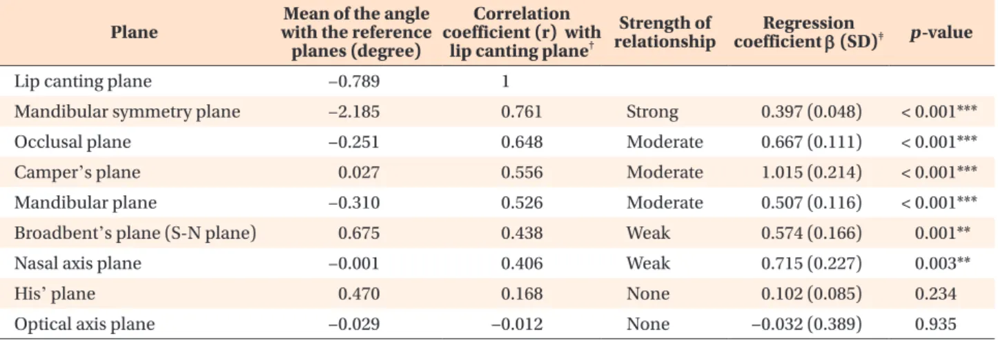
Pearson’s correlation analysis revealed a strong cor-relation between the mandibular symmetry plane and the lip canting plane (0.761). The other planes showed moderate correlations in the following order: occlusal plane (0.648), Camper’s plane (0.556), and mandibular plane (0.526). Broadbent’s plane (0.438) and the nasal axis plane (0.406) showed a weak correlation with the lip canting plane, whereas His’ plane (0.168) and the optical axis plane (–0.012) did not show any significant correlation (Table 3).
Simple regression analysis
In simple regression analysis, the regression coefficient (β) for each plane was determined as follows: mandibu-lar symmetry plane, 0.397; occlusal plane, 0.667;
Camp-er’s plane, 1.015; mandibular plane, 0.507; Broadbent’s plane, 0.574; nasal axis plane, 0.715; His’ plane, 0.102; and optical axis plane, –0.032.
Lip canting showed the strongest correlation with the planes associated with the lower face, followed by the planes associated with the midfacial region. The planes associated with the cranium showed the weakest corre-lation (Table 3).
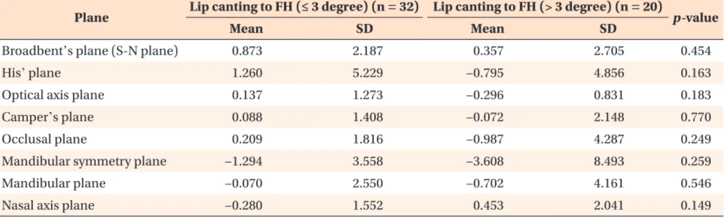
Craniofacial plane inclinations according to the degree of lip canting (> 3° and ≤ 3°)
The various craniofacial plane inclinations showed no statistically significant differences between the clinically prominent (> 3°) and not prominent (≤ 3°) groups (Table 4).
Table 3. Mean correlation coefficients and regression coefficients for various craniofacial planes evaluated in the present study
Plane with the reference Mean of the angle planes (degree)
Correlation coefficient (r) with
lip canting plane†
Strength of
relationship coefficient ββ (SD)Regression ‡ p-value
Lip canting plane −0.789 1
Mandibular symmetry plane −2.185 0.761 Strong 0.397 (0.048) < 0.001***
Occlusal plane −0.251 0.648 Moderate 0.667 (0.111) < 0.001***
Camper’s plane 0.027 0.556 Moderate 1.015 (0.214) < 0.001***
Mandibular plane −0.310 0.526 Moderate 0.507 (0.116) < 0.001***
Broadbent’s plane (S-N plane) 0.675 0.438 Weak 0.574 (0.166) 0.001**
Nasal axis plane −0.001 0.406 Weak 0.715 (0.227) 0.003**
His’ plane 0.470 0.168 None 0.102 (0.085) 0.234
Optical axis plane −0.029 −0.012 None −0.032 (0.389) 0.935
SD, Standard deviation. **p < 0.01, ***p < 0.001. †Pearson’s correlation analysis. ‡Simple regression analysis.
Figure 6. Schematic diagram of the method used for mea-suring the angle between two planes.
FH plane, Frankfort horizontal plane.
x
N-perpendicular plane
FH plane
DISCUSSION
The purpose of this study was to identify the craniofa-cial planes showing a strong correlation with lip canting in a 3D virtual model. Our findings revealed lip canting was strongly correlated with the mandibular symmetry plane.
Lip canting occurs as a result of hard and soft tissue incongruity, including skeletal and muscular inclinations, and is known to be influenced by the occlusal plane, maxillary canting, the difference between the lengths of the two mandibular rami, and menton deviation.5,10,20,21
Midsagittal plane setting is important in the research on facial asymmetry, as the asymmetry and its degree are determined in reference to these planes. In most studies, researchers have used the nasion, sella, crista galli, and ANS as landmarks to set the midsagittal plane.22
How-ever, this sagittal plane is not reliable when there is cra-nial or midfacial asymmetry.23 In order to overcome this
problem, Ras et al.24 proposed that the plane vertically
bisecting the horizontal reference plane should be used as the midsagittal plane. They also mentioned that the orbital structures may be highly reliable in patients with facial asymmetry because growth is normally completed after 8 years of age. On the basis of this concept, we set the plane perpendicular to the FH plane and passing through the nasion as the midsagittal plane in the pres-ent study.
According to Table 3, among the planes associated with the cranium, Broadbent’s plane showed a signifi-cant correlation with lip signifi-canting, whereas the optical axis plane showed no correlation. The cranium is sepa-rated from the midfacial and lower facial regions; there-fore, it is not directly related to the lip and surrounding tissues. The lack of a correlation between the optical axis plane and the lip canting plane could be attributed
to the exclusion of patients with severe eye dystopia in the present study.
Among the planes associated with the midface, Camp-er’s plane and the occlusal plane showed a significant correlation with lip canting, probably because of the muscles originating in the midface, such as the zygo-maticus major and minor and levator labii superioris. In a previous study, maxillary canting due to asymmetric growth was found to affect lip canting because the location of these muscle attachments had changed.5,25
Recently, Freudlsperger et al.26 conducted a 3D analysis
study and reported that changes in the occlusal plane after orthognathic surgery affected the improvement in lip canting. However, His’ plane is defined with the ANS and opisthion, which are points associated with hard tis-sues. Therefore, the peri-oral muscles, which can affect lip canting, are not related to this plane. In the present study, the planes associated with the lower face showed a relatively strong correlation with the lip canting plane, with the mandibular symmetry plane showing the strongest correlation. These results are similar to those reported by Lee et al.12 and Hwang et al.21 on the basis
of 2D images. In our 3D study, it was confirmed that menton deviation and dental inclination were the most influential factors with regard to lip canting.
Ferrario et al.27 reported that lip canting of < 3° is
generally difficult for people to perceive. Therefore, we divided our subjects into clinically prominent and not prominent groups in order to evaluate the differ-ences between patients with clinical lip canting (> 3°) and those without prominent lip canting. However, no significant difference was observed between the two groups, as opposed to our expectation. These results indicate that the clinical management of a patient with severe noticeable lip canting may not require measures additional to those used for a patient without
remark-Table 4. Comparison of various craniofacial plane inclinations between two groups stratified according to the degree of lip canting (> 3° and ≤ 3°)
Plane Lip canting to FH (≤ 3 degree) (n = 32) Lip canting to FH (> 3 degree) (n = 20) p-value
Mean SD Mean SD
Broadbent’s plane (S-N plane) 0.873 2.187 0.357 2.705 0.454
His’ plane 1.260 5.229 −0.795 4.856 0.163
Optical axis plane 0.137 1.273 −0.296 0.831 0.183
Camper’s plane 0.088 1.408 −0.072 2.148 0.770
Occlusal plane 0.209 1.816 −0.987 4.287 0.249
Mandibular symmetry plane −1.294 3.558 −3.608 8.493 0.259
Mandibular plane −0.070 2.550 −0.702 4.161 0.546
Nasal axis plane −0.280 1.552 0.453 2.041 0.149
Mann–Whitney test was performed.
able lip canting. However, further research based on the results before and after treatment is necessary to sub-stantiate this assumption.
In the case of 3D analysis using CT, it is necessary to select four points for a specific plane. Generally, bilateral anatomical landmarks are used. However, if two land-marks show a large positional difference, they cannot be used as reference points. In addition, an error may occur when defining a plane having only a single point in the midline, such as the sella. For this reason, the present study only included cases where there was no significant distance between bilateral landmarks and the sella and opisthion were located on the midsagittal line.
Some scholars have reported that skeletal asymme-try can be masked by soft tissues such as muscles and skin.28 Peck et al.29 reported that many patients with
skeletal asymmetry exhibit symmetrical facial soft tissue features, and that there is a difference between skeletal asymmetry and soft tissue asymmetry. Therefore, resolu-tion of any soft tissue asymmetry should be the basic goal of diagnosis and treatment for patients with facial asymmetry.12,30 Lip canting, which is an important
ele-ment of soft tissue asymmetry, should be considered in addition to the facial muscles and skeletal structure.
Several studies involving the prediction of soft tissue contours in orthognathic surgery are being conducted, and clinicians attempt to resolve lip canting by maxillary canting correction in most studies. To the best of our knowledge, the present study is the first to show that the mandibular symmetry plane is strongly correlated with the lip canting plane.
This study has some limitations. First, only preopera-tive CT scans were studied. Second, the sample size was small. Third, because only the preoperative condition was analyzed, no analysis was performed to determine whether the degree of lip canting reduced after sur-gery. Fourth, cases of severe eye and ear dystopia were excluded; therefore, patients with midfacial asymmetry were not entirely considered. Further studies should set other planes that are not affected by the positions of the orbitale and porion. Choi et al.31 measured midfacial
asymmetry using the basion-perpendicular plane; such planes will also help in determining the correlations be-tween midfacial asymmetry and lip canting.
Nevertheless, the findings of this study are clinically meaningful because, to the best of our knowledge, there is no report on the correlation between the planes used in 3D evaluation and the clinical lip canting plane. In addition, the craniofacial planes that were correlated with lip canting in the present study may change after orthognathic surgery. There is a paradigm shift from traditional 2D analysis to 3D analysis using CT. The sig-nificance of the present study lies in the fact that lip canting, which was traditionally analyzed using only 2D
photographs, was correlated with other 3D craniofacial planes. However, further research should determine how lip canting improves with changes in these planes.
CONCLUSION
The findings of this study suggest that lip canting is strongly correlated with the mandibular symmetry plane, which includes menton deviation. This finding may have clinical implications for the treatment of patients requiring correction of lip canting. Further studies are necessary for evaluating the changes in lip canting after orthognathic surgery.
CONFLICTS OF INTEREST
No potential conflict of interest relevant to this article was reported.
REFERENCES
1. Cohen MM Jr, Richieri-Costa A, Guion-Almeida ML, Saavedra D. Hypertelorism: interorbital growth, measurements, and pathogenetic considerations. Int J Oral Maxillofac Surg 1995;24:387-95.
2. Huang CS, Liu XQ, Chen YR. Facial asymmetry in-dex in normal young adults. Orthod Craniofac Res 2013;16:97-104.
3. Kim SJ, Choi JY, Baek SH. Evaluation of canting correction of the maxillary transverse occlusal plane and change of the lip canting in Class III two-jaw orthognathic surgery. Angle Orthod 2012;82:1092-7.
4. Choi JY, Choi JP, Lee YK, Baek SH. Simultaneous correction of hard- and soft-tissue facial asymmetry: combination of orthognathic surgery and face lift using a resorbable fixation device. J Craniofac Surg 2010;21:363-70.
5. Kim YH, Jeon J, Rhee JT, Hong J. Change of lip cant after bimaxillary orthognathic surgery. J Oral Maxillofac Surg 2010;68:1106-11.
6. Padwa BL, Kaiser MO, Kaban LB. Occlusal cant in the frontal plane as a reflection of facial asymmetry. J Oral Maxillofac Surg 1997;55:811-6; discussion 817.
7. Chu EA, Farrag TY, Ishii LE, Byrne PJ. Threshold of visual perception of facial asymmetry in a facial pa-ralysis model. Arch Facial Plast Surg 2011;13:14-9. 8. Sarver DM, Ackerman MB. Dynamic smile
visualiza-tion and quantificavisualiza-tion: part 1. Evoluvisualiza-tion of the concept and dynamic records for smile capture. Am J Orthod Dentofacial Orthop 2003;124:4-12.
9. Song WC, Koh KS, Kim SH, Hu KS, Kim HJ, Park JC, et al. Horizontal angular asymmetry of the face in
korean young adults with reference to the eye and mouth. J Oral Maxillofac Surg 2007;65:2164-8. 10. Gazit-Rappaport T, Weinreb M, Gazit E. Quantitative
evaluation of lip symmetry in functional asymmetry. Eur J Orthod 2003;25:443-50.
11. Trpkova B, Major P, Nebbe B, Prasad N. Craniofacial asymmetry and temporomandibular joint internal de-rangement in female adolescents: a posteroanterior cephalometric study. Angle Orthod 2000;70:81-8. 12. Lee MS, Chung DH, Lee JW, Cha KS. Assessing
soft-tissue characteristics of facial asymmetry with photographs. Am J Orthod Dentofacial Orthop 2010;138:23-31.
13. Ludlow JB, Gubler M, Cevidanes L, Mol A. Precision of cephalometric landmark identification: cone-beam computed tomography vs conventional ceph-alometric views. Am J Orthod Dentofacial Orthop 2009;136:312.e1-10; discussion 312-3.
14. Lonic D, Sundoro A, Lin HH, Lin PJ, Lo LJ. Selection of a horizontal reference plane in 3D evaluation: Identifying facial asymmetry and occlusal cant in or-thognathic surgery planning. Sci Rep 2017;7:2157. 15. Trpkova B, Prasad NG, Lam EW, Raboud D, Glover
KE, Major PW. Assessment of facial asymmetries from posteroanterior cephalograms: validity of reference lines. Am J Orthod Dentofacial Orthop 2003;123:512-20.
16. De Riu G, Meloni SM, Baj A, Corda A, Soma D, Tul-lio A. Computer-assisted orthognathic surgery for correction of facial asymmetry: results of a ran-domised controlled clinical trial. Br J Oral Maxillofac Surg 2014;52:251-7.
17. Kang YH, Kim BC, Park KR, Yon JY, Kim HJ, Tak HJ, et al. Visual pathway-related horizontal reference plane for three-dimensional craniofacial analysis. Orthod Craniofac Res 2012;15:245-54.
18. Lahori M, Nagrath R, Malik N. A cephalometric study on the relationship between the occlusal plane, ala-tragus and Camper's lines in subjects with Angle's Class I, Class II and Class III occlusion. J In-dian Prosthodont Soc 2013;13:494-8.
19. Ferrario VF, Sforza C, Poggio CE, Tartaglia G. Dis-tance from symmetry: a three-dimensional evalu-ation of facial asymmetry. J Oral Maxillofac Surg 1994;52:1126-32.
20. Cho JH, Kim EJ, Kim BC, Cho KH, Lee KH, Hwang HS. Correlations of frontal lip-line canting with
cra-niofacial morphology and muscular activity. Am J Orthod Dentofacial Orthop 2007;132:278.e7-14. 21. Hwang HS, Youn IS, Lee KH, Lim HJ. Classification
of facial asymmetry by cluster analysis. Am J Orthod Dentofacial Orthop 2007;132:279.e1-6.
22. Tuncer BB, Ataç MS, Yüksel S. A case report com-paring 3-D evaluation in the diagnosis and treat-ment planning of hemimandibular hyperplasia with conventional radiography. J Craniomaxillofac Surg 2009;37:312-9.
23. Terajima M, Nakasima A, Aoki Y, Goto TK, Toku-mori K, Mori N, et al. A 3-dimensional method for analyzing the morphology of patients with maxillo-facial deformities. Am J Orthod Dentomaxillo-facial Orthop 2009;136:857-67.
24. Ras F, Habets LL, van Ginkel FC, Prahl-Andersen B. Method for quantifying facial asymmetry in three dimensions using stereophotogrammetry. Angle Or-thod 1995;65:233-9.
25. Marinetti CJ. The lower muscular balance of the face used to lift labial commissures. Plast Reconstr Surg 1999;104:1153-62; discussion 1163-4.
26. Freudlsperger C, Rückschloß T, Ristow O, Bodem J, Kargus S, Seeberger R, et al. Effect of occlusal plane correction on lip cant in two-jaw orthognathic sur-gery - a three-dimensional analysis. J Craniomaxil-lofac Surg 2017;45:1026-30.
27. Ferrario VF, Sforza C, Miani A, Tartaglia G. Craniofa-cial morphometry by photographic evaluations. Am J Orthod Dentofacial Orthop 1993;103:327-37. 28. Yogosawa F. Predicting soft tissue profile changes
concurrent with orthodontic treatment. Angle Or-thod 1990;60:199-206.
29. Peck S, Peck L, Kataja M. Skeletal asymmetry in es-thetically pleasing faces. Angle Orthod 1991;61:43-8.
30. Van Hemelen G, Van Genechten M, Renier L, Des-medt M, Verbruggen E, Nadjmi N. Three-dimension-al virtuThree-dimension-al planning in orthognathic surgery enhances the accuracy of soft tissue prediction. J Craniomax-illofac Surg 2015;43:918-25.
31. Choi YK, Park SB, Kim YI, Son WS. Three-dimen-sional evaluation of midfacial asymmetry in patients with nonsyndromic unilateral cleft lip and palate by cone-beam computed tomography. Korean J Orthod 2013;43:113-9.