particles disperse and become airborne. In particular, particles of size less than 2.5 microns(PM2.5) can cause serious health problems. The effect of coal particles on health has been discussed in studies related to the control of airborne dust emitted from coal mines and coal-fired power plants(Lockwood and Fana, 2014; Gottlieb et al., 2010). Fugitive fine coal particulate is the one that is not carried by the flue gas passing through the stack(Sandy Creek Services, 2015; Currier and Neal, 1979). Examples of fugitive particles include coal particulates from coal handling and processing units and fine parti- cles from fly ash and bottom ash handling units.
Local or centralized fugitive dust control units are 1. Introduction
In coal-fired power plants, coal is processed before feeding it to the boiler for combustion. During the processing of the coal, a significant amount of par- ticulate is emitted inside the housing and to the atmosphere. Coal particulate is emitted from main- ly during the crushing, grinding, milling, and trans- portation of coal(Miller, 2011). In plants wherein the particulate handling units are located outside the building, the contamination of the surrounding air due to the dust emitted from these facilities is a matter of concern for the operators of the plant. Dur- ing the coal handling and processing of coal, coal
p-ISSN 1598-7132, e-ISSN 2383-5346
기술자료
Control of Fugitive Fine Coal Particulate Emissions from Coal Handling System at Coal-Fired Power Plants using a Two-Stage Vortex Scrubber
Kwang-Deuk Kim, Naim Hasolli, Kang-San Lee, Jae-Rang Lee, Young-Ok Park
*
Clean Fuel Department, Korea Institute of Energy ResearchAbstract Fugitive fine coal particulate is emitted from fuel coal transportation and handling plants at coal fired power plants. Fine coal particulate is emitted as result of the coal processing before feeding it to the combustor for generation of steam.
Other particles such as bottom ash and fly ash are emitted from coal combutors. Most of coal fired power plants are applying various technologies, bag filtration and wet scrubbing, to remove the fugitive fine coal particulates. A two-stage vortex scrubber is proposed in this paper. Tests were performed by injecting fly ash particles as a test dust. The vortex scrubber was operated in two modes: no-drain and continuous water drain mode. The system pressure drop was controlled using a flow control unit to operate the scrubber at certain test parameters. The inlet particle concentration maintained at three levels of 0.17, 0.23 and 0.33 g/m3. The particle concentrations were measured at the inlet and outlet of the scrubber. The results shown the high particle collection effieicies with 83.6% for PM1, 97.6% for PM2.5 and 99.1% for PM10 at pressure drop of 230mmAq and operated in the continuous water drain mode. For the purpose of water-air interface visualization, computational fluid dynamics(CFD) tool Fluent was used. Integral module of the Fluent, called Volume of Fluid (VoF), was used to simulate the two phase system in the water batch drain operation mode.
Key words: Vortex scrubber, Wet scrubbing, Particle collection efficiency, Fugitive fine coal particulate, Pressure drop 접수일 2019년 3월 18일 수정일 2019년 4월 4일 채택일 2019년 4월 19일 Received 18 March 2019 Revised 4 April 2019 Accepted 19 April 2019
*Corresponding author Tel : +82-(0)42-860-3625 E-mail : [email protected]
effect of water content on the performance of a bag filter unit. In the case of open facilities, the coal par- ticle control unit involves supressing the dust using water spray(Tessum and Raynor, 2015). Wet scrub- bers are more suitable for the safe control of coal particle emitted from coal handling plants(Schnelle and Brown, 2016; Brauer and Varma, 2012; Nath and Cholakov, 2009). All types of wet scrubber, independent on the size and shape of the separation unit, apply the same mechanisms for particle sepa- ration from gas stream, the impaction(inertial imp- ingement), interception and diffusion mechanism.
The types of wet scrubbers are classified bsed on the gas-liquid interface. There are four types of the inter- faces created by various processes, liquid films(pack- ed bed scrubbers), liquid jets(jet scrubbers), drops (venturi scrubbers, vortex scrubbers, rotating disc scrubbers) and bubbles. Among other types of wet scrubber units, vortex scrubbers are the most simple and low energy demanding units(Brauer and Varma, 2012). Depending on the shape of the unit, vortex (or self-induced spray) scrubbers can employ two types of gas-liquid interface, liquid film which can be build on the internal walls of the scru bber and on the walls of the baffles, if any is install ed, and drops created and dispersed by the friction between the high velocity streaming gas flow thorough the vortex channel parallel to the liquid surface, as noted in Brauer and Varma(2012). The gas velocity inside the channel should be in the range between 15 to 30 m/s. The higher the relative flow of dust laden gas to the droplets the higher the collection efficiency.
High gas velocities are directly related to high pres- sure drop of the unit. Pressure drop of the scrubber units is related to the energy required for movement
tex channels, arran ged in opposite direction to each other. Rotoclone N represents a single stage scrub- ber with two channels in parallel arrangement.
In this study, a pilot scale two-stage vortex scrub- ber was developed and tested using fly ash as a test dust. As stated in Brauer and Varma(2012), if the scrubber is arranged as two stage unit, the particle collection efficiency can be improved with the incr- ease of pressure drop. In this study the authors aimed to demonstrate that a two stage vortex scrubber can be applied for improvement of the particle collection efficiency without any excessive pressured drop inc- rease. Vortex scrubber is suitable for processing high volume of air and can be used for the control of cen- tralized fugitive fine coal particulate inside buildings where coal is processed fuel coal for combustion. The two stage vortex scrubber is composed of two vortex chambers with goal of improving the particle collec- tion efficiency at low pressure drop. The unit was operated by varying the pressure drop from 200 mmAq to 240mmAq and the particle concentration from 0.17g/m3 to 0.33g/m3. In terms of the water level inside the scrubber, two operating modes were studied, the water batch drain(which would repre- sent a single stage scrubber unit) and the continuous drain mode(which would represent an effective two stage scrubbing unit). A simple 3D volume of fluid (VoF) model was used for a CFD simulation.
2. Experimental
2. 1 Test system setup
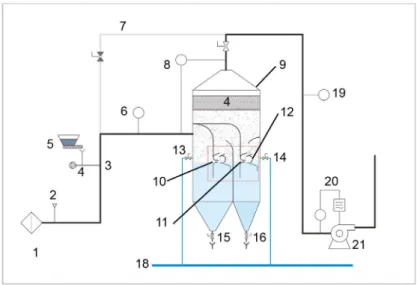
The test system comprises an air prefilter, gas and solid particle injection ports, a coal dust feeding unit,
a two-stage vortex scrubber, ports for measuring the particle concentration, a flow control unit, and an induced draft(ID) fan. The air prefilter(1) was used to remove airborne particles from the incoming air.
To simulate the operating conditions of a real site, ports were made for injecting various gases(2) and solid particles(3). The feeding unit comprises a solid particle metering feeder(5), a particle ejector(4), and a compressed air pressure regulator. These parts were optimized for a uniform distribution of the solid particles inside the inlet duct of the system. The vortex scrubber(9) consists of core elements, two vortex channels(10, 11) with breaking baffles(12), water containers for controlling the water level in both the channels, and a water droplet separating demister(13). The casing of the scrubber was equ- ipped with drain valves for draining the particle-con- taminated water settled at the bottom of the casing (16, 17) and for controlling the operating mode, ben- ch or continuous water removal(14, 15). The solid particle concentration was measured at the inlet(6) and outlet(19) of the scrubber. The flow control unit (20) and the ID fan(21) were installed for controlling the flow rate and system pressure drop, respectively.
Figs. 1 and 2 show the schematic and the real image of the pilot scale system, respectively.
2. 2 Particle measurement
A particle spectrometer(model 1108, Grimm, Germany) was used for measuring the particle con- centration. The range of particle size that could be measured using this unit was 0.2 to 23 microns. The online particle measurements at the port(6) were done periodically to check the inlet concentration which was maintained constant throughout the test- ing time and the measurement at the port(19) were performed continuously. The gathered data were processed using the spectrometer data aquisition software. To evaluate the solid particle removal effi- ciency, online measurements were conducted using a spectrometer, and the efficiency was calculated using the following equation.
Eff=(Ci-Co)×(1/Ci)×100[%] (1) where Ci and Co denote the inlet and outlet particle concentrations, respectively.
2. 3 Test method and operating modes
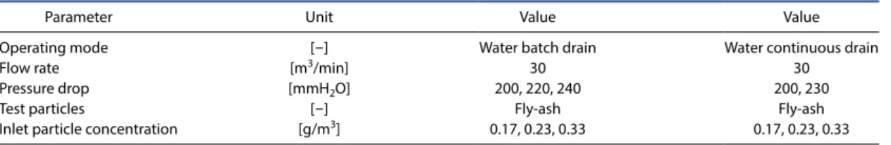
Table 1 lists the test parameters for the two modes.The flow rate was kept constant at 30m3/min(under room conditions) for all tests. To evaluate the effect of water drain and with it the water level control, two modes were operated: batch and continuous drain
Fig. 1. Schematic of pilot scale two-stage vortex scrubber.
modes. In the batch drain mode, the system was filled with water until the water level exceeded the height of the second vortex channel. The tests were then started, and the water valves were not opened until the tests were completed. In the continuous drain mode, the system was continuously filled with water, and the drain valves were operated to remove the bottom settled water from the system. In both the modes, the flow was controlled to keep the system pressure drop at a certain value, as listed in Table 1.
2. 4 Test material
Fly ash from a coal-fired power plant(research institute internal plant) was used as the test material.
Three levels of feeding rate were set. These values of dust concentration are common at coal handling sites.
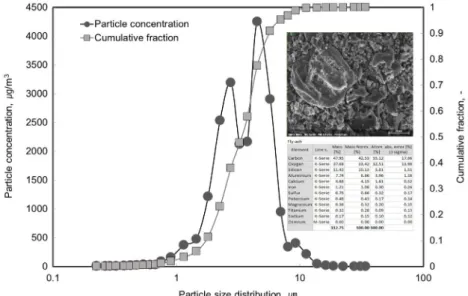
Fig. 3 shows the fly ash particle size distribution. The
mean particle size is 3.65 microns.
2. 5 Operating principle of the two - stage vortex scrubber
Vortex scrubbers operate based on the water dis- persion inside the vortex channel with dimensions 15 mm open slit and the length of 1200mm as shown in Fig. 4. Thus, the generated drops flow with a high speed along with the flue gas and follow the chamber flow direction. Inside the vortex chamber, the solid particles and liquid drops move relative to each other, and this motion is mainly responsible for particle separation. After passing through the vortex cham- ber, the liquid drops and flue gas get separated. The drops containing solid particles settle down on the liquid surface and the flue gas, which is free from particles, flows toward the outlet duct. The remain- Table 1. Test parameters and operating mode.
Parameter Unit Value Value
Operating mode [-] Water batch drain Water continuous drain
Flow rate [m3/min] 30 30
Pressure drop [mmH2O] 200, 220, 240 200, 230
Test particles [-] Fly-ash Fly-ash
Inlet particle concentration [g/m3] 0.17, 0.23, 0.33 0.17, 0.23, 0.33
Fig. 2. Real image of pilot scale two-stage vortex scrubber.
ing fine drops dispersed in the flue gas are finally separated inside the demister before reaching the outlet duct. In the case of the two-stage vortex scrub- ber, the same principle is employed for both the sepa- ration stages. The water level is controlled by opening the water filling and drain valves installed on the sys- tem casing, as shown in Fig. 1(red colored square).
At initial stage, the water level is above the channel of vortex chamber as shown in Fig. 4a. After the start of operation, the level of water is changed according to the system pressure drop as shown in Fig. 4b.
3. Results and Discussion
Two modes of operation were considered, and the tests were performed at a fixed system pressure drop and by varying the particle injection rate. Both the modes were operated under the same laboratory con- ditions and with the same dust particle inlet concen- trations.
3. 1 Water batch drain mode
During the operation in this mode, the system was Fig. 4. Particle removal inside the vortex chamber: operating principle of the two-stage vortex scrubber system at (a) initial status and (b) during operation.
(a) (b)
Fig. 3. Test particle size distribution, Scanning Electron Microscope(SEM) 1000×image and the consisting elements.
initially filled with water, and the tests were then started. At the point where the system pressure drop reached a value of 200mmAq, the fly ash was inject- ed, and the particle removal efficiency was evaluated
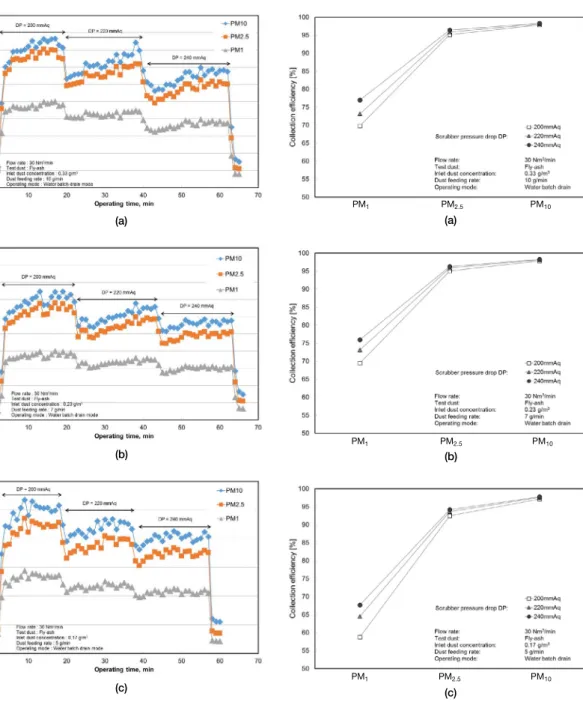
by measuring the solid particle concentration at the inlet and outlet of the scrubber unit. Fig. 5 shows the outlet concentrations of PM1, PM2.5, and PM10 parti- cles for scrubber pressure drop values of 200, 220,
PM1 PM2.5 PM10
PM1 PM2.5 PM10
(a)
(b)
(c)
Fig. 6. Collection efficiency of PM1, PM2.5, and PM10 as a func- tion of the scrubber pressure drop at variation of inlet particle concentrations in the water batch drain mode.
PM1 PM2.5 PM10
Fig. 5. Particle outlet concentration of PM1, PM2.5, and PM10 particles as a function of the scrubber pressure drop at varia- tion of inlet particle concentrations in the water batch drain mode.
(a)
(b)
(c)
and 240mmAq. With the increase in the pressure drop, the concentrations of the particles decr ease. A higher pressure drop means that the turbulence in- side the vortex chamber is high due to high velocities inside the vortex channel, and the particles tend to
collide with the water droplets and settle down on the water surface, thus separating the particles from the gas stream. The maximum concentrations of PM1, PM2.5, and PM10 particles reached 245, 380, and 425μg/m3, respectively(Fig. 5a), corresponding
(a) (b)
(c) (d)
(e) (f)
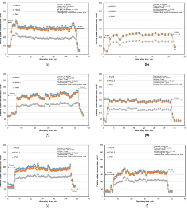
Fig. 7. Particle outlet concentrations of PM1, PM2.5, and PM10 as a function of the scrubber pressure drop and particle inlet con- centration in the water continuous drain mode.
3. 2 Water continuous drain mode
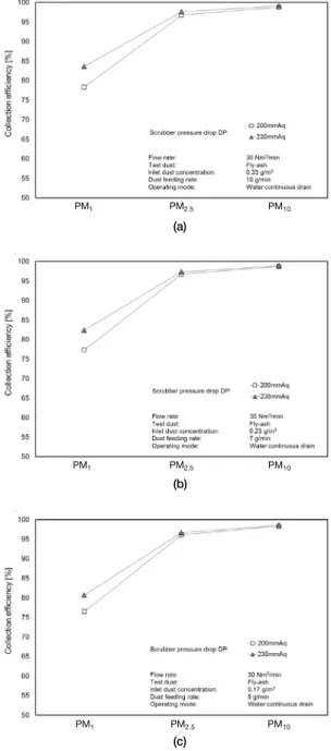
During this operation, both the chambers were continuously filled with water and drained. At the point where the system pressure drop reached the value of interest, the fly ash was injected, and the par- ticle removal efficiency was evaluated. Fig. 7 shows the outlet concentrations of PM1, PM2.5, and PM10 particles for scrubber pressure drop values of 200 and 230mmAq. Similar to the bench drain mode, with the increase in the pressure drop, the concentrations of the particles decrease. The maximum concentra- tions of PM1, PM2.5, and PM10 particles differ depen- ding on the scrubber pressure drop. Thus, for the same inlet concentration of 0.33g/m3, the particle outlet concentration was lower when the system was operated at 230mmAq. At a low inlet concentration of 0.17g/m3, the outlet concentrations at system pres- sure drops of 200 and 230mmAq are only slightly dif- ferent. Fig. 8 shows the particle collection efficiency as a function of the scrubber pressure drop in the water continuous drain mode. The collection efficien- cy for particle size smaller than 2.5μm is expressed as a function of pressure drop and the inlet duct concen- tration. For PM10 particles the difference this differ- ence is small because the larger particles are separated from the gas stream by the liquid film and by large droplets. Particles, small enough to follow the gas stream, are separated by small droplets. The higher the pressure drop the higher the velocity inside the vortex channel. With the increase in velocity the size of droplets decreases. Small droplets can contribute to the capture of fine particles. This is conform state- ment found in the literature Yi(2009).
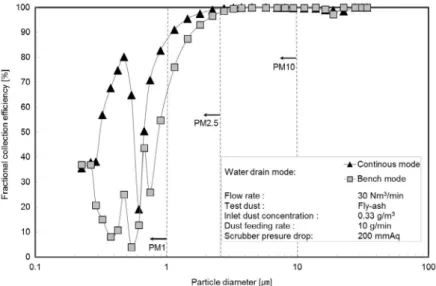
Fig. 9 shows the fractional collection efficiency as a function of the particle size. In the water continuous
drain mode, the chambers1 and 2 are filled with water and drained continuously. This leaves both the vortex chambers wet all the time, and the particles get sepa- rated inside both chambers. Thus, the removal effi-
PM1 PM2.5 PM10
PM1 PM2.5 PM10 PM1 PM2.5 PM10
(a)
(b)
(c)
Fig. 8. Collection effieciency of PM1, PM2.5, and PM10 as a function of the scrubber pressure drop and particle inlet con- centration in the water continuous drain mode.
ciency of PM1 in this mode is significantly imp roved compared to operating the vortex scrubber with no water filling and no drain during the tests. Large par- ticles are removed by the impingement of the parti- cles on the bulk water layer of the scrubbing chamber whereas the small particles are separated by the water droplets dispersed in the flowing air. In order to achieve good particle removal results, large number of small droplets need to be generated. In case of the batch drain mode, water is present in the first cham- ber only at the begin of the test, only the second vor- tex chamber is practically in operation. In case of the continuous drain mode, both chambers are filled with water to keep the level constant. The subsequent par- ticle separation in two chambers results in improve- ment of the efficiency for particles of the size less than 2.5μm as indicated in the Fig. 9. The improvement of the collection efficiency in other types of scrubbers with two stage arrangements is reported in Brauer and Varma(2012).
4. CFD Simulation Results
The following assumptions and simplifications were made to make the simulation possible. The
ducts are rectangular, and the inlet and outlet ducts have the same cross-sectional area as the original model shown in Fig. 2. In Fig. 10, the 3D model is displayed with boundary information and indication of the initial water level(red line).
In the case of vortex scrubbers, the process can be simulated in Fluent only by using the VoF method.
The water phase is indicated in red and the air is indicated in blue as shown in Fig. 11. The unsteady Fig. 9. Comparison of fractional collection efficiency in the water drain mode.
Fig. 10. CFD Simulation boundary conditions.
mode was used for the simulation for a total simula- tion time of 1.45 s. Table 2 lists the operating condi- tions. After the simulation is completed, the data are loaded into the post-processing tool CFD Post as part of the Fluent package. As the system runs in the suc- tion mode, air is first drawn from the outlet and then
flows through the nozzles after the water level reduc- es. In this study, the initial water level was fixed in all the three cases.
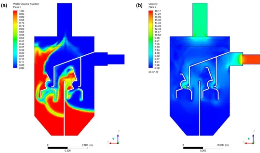
After 1.45 s of operation, water moves to the sec- ond chamber of the vortex scrubber, and the actual particle removal takes place only inside the second Fig. 11. (a) Cutting plane contours of water/air volume concentration, and (b) air flow velocity distribution after 1.45s of operation.
Fig. 12. Cutting plane contours of (left) scrubber pressure and (right) particle mass concentration at time 1.45 s of operation.
(a) (b)
vortex channel as shown in Fig. 11a. High flow veloc- ities are visible in the regions directly following the nozzles and baffles installed in front of the scrubbing nozzles as shown in Fig. 11b. Fig. 12a shows the pres- sure distribution inside the scrubber. As expected, the pressure drop is highest inside the second vortex chamber behind the second nozzle. Most of the par- ticles are separated inside the second chamber, but some of them escape the second vortex channel and move toward the scrubber outlet as shown in Fig.
12b.
Conclusions
The water level in the first vortex chamber varied with respect to the operating time at the water batch drain mode. The system was operated as a closed material system related to water. The water moved from the first chamber to the second chamber, rem- ained in the first chamber with water below the vor- tex channel. Most of the particles were separated by the highly turbulent flow inside second chamber. The system operated in this mode is representative of the one stage scrubber unit. For the tests operated at water continuous drain mode, the same water level remained, and the water inside the first and second chamber was drained to keep the constant scrubber pressure drop throughout the test. As both the cham- bers were flooded with water and the separated parti- cles left the system via drain valves, the particle col- lection efficiency was improved, particularly for PM2.5 particles. The two stage vortex scrubber has good performance compared to one stage arrange- ment.
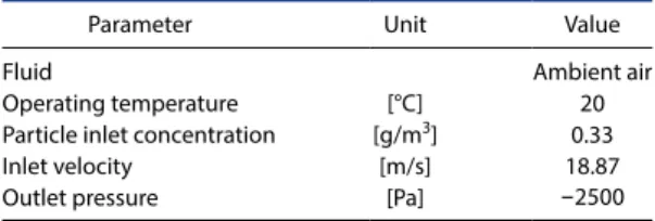
Table 2. Operating and boundary conditions.
Parameter Unit Value
Fluid Ambient air
Operating temperature [°C] 20
Particle inlet concentration [g/m3] 0.33
Inlet velocity [m/s] 18.87
Outlet pressure [Pa] -2500
In the water batch drain mode operation, water moves from the first to the second chamber. As a result, only the second vortex chamber is wet, and most of the particles are separated inside the second vortex chamber.
To obtain a turbulent flow with high gas/ droplet relative velocities, the opening of the nozzle should be small enough to create vortex channel velocities high- er than 20m/s. This is done by increasing the pres- sure drop of the system. The results show that for the same particle inlet concentration and water drain mode conditions, the particle removal efficiency was increased with increasing pressure drop. The pres- sure drop of 230mmAq is well within the range of commercial vortex scrubbers.
Because of the limitation of the CFD tool and the complexity of the three-phase system, the interaction between the solid particles and the water drops was not analyzed. The results show the effect of the water drain mode operation and flow rate variation on the water level inside the two vortex chambers.
Future work will focus on precise water level con- trol and optimization of vortex chambers to reduce the system pressure drop and simultaneously to im- prove the particle collection efficiency.
Acknowledgments
This work was supported by the Korea Institute of Energy Technology Evaluation and Planning(KET EP) and the Ministry of Trade, Industry & Energy(MO TIE) of the Republic of Korea(No. 20171120100 560).
References
AAF(2018) AAF International, http://aaflatinoamerica.com/
wpcontent/uploads/ 2018/09/rotoclone-n-bro chure.pdf(accessed on April. 2, 2019).
Brauer, H., Varma, Y.B.G.(2012) Design and operation of wet scrubbers, Air Pollution Control Equipment, Spring- er, Berlin, Heidelberg, 107-149.
365-379, DOI: 10.5277/ppmp160131.
Lockwood, A.H., Fana, F.(2014) Ash in lungs, how breathing coal ash is hazardous to your health. http://earth justice.org/sites/default/files/files/Ash_In_Lungs_1.
pdf(accessed on March. 6, 2019).
Miller, B.G.(2011) Anatomy of coal-fired power plant, Clean Coal Engineering Technology, Butterworth-Heine- mann, 219-250, DOI : 110.1016/B978-1-85617-710- 8.00006-6.
Nath, B., Cholakov, G.S.(2009) Wet scrubbers, Pollution Control Technologies, Volume 1, EOLSS Publishers, 290-317.
Sandy Creek Services(2015) Coal combustion residuals fugi- tive dust control plan, http://www.sandycreekpow- er.net/reports/pdf/R121616-Dust-Control-Plan.pdf (accessed on March. 6, 2019).
Schnelle Jr, K.B., Brown, C.A.(2016) Design and application of
Control, Volume II, Eolss Publishers, Oxford, 212- 221.
Authors Information
Kwang-Deuk Kim
(Korea Institute of Energy Research, Principal Researcher) Naim Hasolli
(Korea Institute of Energy Research, Senior Researcher) Kang-San Lee
(Korea Institute of Energy Research, Researcher) Jae-Rang Lee
(Korea Institute of Energy Research, Researcher) Young-Ok Park
(Korea Institute of Energy Research, Principal Researcher)