INTRODUCTION
Given recent technical advances, cardiac magnetic resonance (CMR) imaging is widely used in many areas of
Guideline for Cardiovascular Magnetic Resonance Imaging from the Korean Society of Cardiovascular Imaging—Part 1: Standardized Protocol
Yeseul Jo, MD
1*, JeongJae Kim, MD
2*, Chul Hwan Park, MD
3, Jae Wook Lee, MD
4, Jee Hye Hur, MD
5, Dong Hyun Yang, MD
6, Bae Young Lee, MD
7, Dong Jin Im, MD
8, Su Jin Hong, MD
9, Eun Young Kim, MD
6, Eun-Ah Park, MD
10, Pan Ki Kim, PhD
8, Hwan Seok Yong, MD
111Department of Radiology, Incheon St. Mary’s Hospital, College of Medicine, The Catholic University of Korea, Incheon, Korea; 2Department of Radiology, Jeju National University Hospital, Jeju, Korea; 3Department of Radiology and Research Institute of Radiological Science, Gangnam Severance Hospital, Yonsei University College of Medicine, Seoul, Korea; 4Department of Radiology, Soonchunhyang University Bucheon Hospital, Bucheon, Korea; 5Department of Radiology, Hanil General Hospital, Seoul, Korea; 6Department of Radiology and Research Institute of Radiology, Asan Medical Center, University of Ulsan College of Medicine, Seoul, Korea; 7Department of Radiology, Eunpyeong St. Mary’s Hospital, College of Medicine, The Catholic University of Korea, Seoul, Korea; 8Department of Radiology and Research Institute of Radiological Science, Severance Hospital, Yonsei University College of Medicine, Seoul, Korea; 9Department of Radiology, Hanyang University Guri Hospital, Hanyang University College of Medicine, Guri, Korea; 10Department of Radiology, Seoul National University Hospital, Seoul, Korea; 11Department of Radiology, Korea University Guro Hospital, Seoul, Korea
Cardiac magnetic resonance (CMR) imaging is widely used in many areas of cardiovascular disease assessment. This is a practical, standard CMR protocol for beginners that is designed to be easy to follow and implement. This protocol guideline is based on previously reported CMR guidelines and includes sequence terminology used by vendors, essential MR physics, imaging planes, field strength considerations, MRI-conditional devices, drugs for stress tests, various CMR modules, and disease/
symptom-based protocols based on a survey of cardiologists and various appropriate-use criteria. It will be of considerable help in planning and implementing tests. In addressing CMR usage and creating this protocol guideline, we particularly tried to include useful tips to overcome various practical issues and improve CMR imaging. We hope that this document will continue to standardize and simplify a patient-based approach to clinical CMR and contribute to the promotion of public health.
Keywords: Heart; Cardiovascular; Magnetic resonance imaging; Protocol; Guideline
Received June 10, 2019; accepted after revision August 12, 2019.
This study was supported by the Guideline Development Fund of the Korean Society of Radiology and Korean Society of Cardiovascular Imaging.
*These authors contributed equally to this work.
This guideline has been published jointly with consent in the Cardiovascular Imaging Asia, Korean Journal of Radiology, and Investigative Magnetic Resonance Imaging.
Corresponding author: Chul Hwan Park, MD, Department of Radiology, Gangnam Severance Hospital, 211 Eonju-ro, Gangnam-gu, Seoul 06273, Korea.
• Tel: (822) 2019-3510 • Fax: (822) 3462-5472 • E-mail: [email protected]; and
Hwan Seok Yong, MD, Cardiothoracic Division, Department of Radiology, Korea University Guro Hospital, 148 Gurodong-ro, Guro-gu, Seoul 08308, Korea.
• Tel: (822) 2626-1342 • Fax: (822) 863-9282 • E-mail: [email protected]
This is an Open Access article distributed under the terms of the Creative Commons Attribution Non-Commercial License (https://
creativecommons.org/licenses/by-nc/4.0) which permits unrestricted non-commercial use, distribution, and reproduction in any medium, provided the original work is properly cited.
cardiovascular disease assessment (1). Currently, health insurance in Korea covers CMR for cardiomyopathy and complex congenital heart disease, though insurance coverage is expected to expand further in 2019, which will Korean J Radiol 2019;20(9):1313-1333
https://doi.org/10.3348/kjr.2019.0398
probably increase the number of tests compared with the past.
In 2010, the Asian Society of Cardiovascular Imaging published standardized protocols for CMR imaging (2) and in 2013 the Society for Cardiovascular Magnetic Resonance published an updated version of the standardized
protocols (3).
Herein, we offer a practical standard CMR protocol for beginners designed to be easy to follow and implement.
This protocol guideline is based on previously reported CMR guidelines (1-9) and includes sequence terminology used by vendors, essential MR physics (10-17), imaging planes (2, 18), field strength considerations (19-25), MRI-conditional devices (10, 20, 26-33), drugs for stress tests (34), various CMR modules (16, 35-46), and disease/symptom-based protocols (47-58) based on a survey of cardiologists, and various appropriate use criteria. It will be of considerable help in planning and implementing tests. We particularly tried to include useful tips to overcome various practical issues and improve CMR imaging.
By addressing CMR usage and creating this protocol guideline, we are working to continue the standardization and simplification of the patient-based approach to clinical CMR and contribute to the promotion of public health. As CMR imaging technology progresses, we will update this guideline at regular intervals.
This protocol guideline is a joint report of the Korean Society of Cardiovascular Imaging and the Korean Society of Radiology.
General Considerations
Appropriate Criteria
CMR imaging is useful in the diagnosis, stratification, treatment planning, prognosis prediction, and therapeutic effect evaluation of various cardiac diseases (53, 59, 60). However, appropriate criteria for disease, ethnicity, socioeconomic status, and the medical insurance system are essential to maximizing its clinical utility (1, 61). In 2014, guidelines for the appropriate use of CMR were published jointly by the Korean Society of Cardiology and the Korean Society of Radiology to guide physicians, imaging specialists, medical associates and patients, and improve the overall performance of the health system (1). In 2017, expert consensus–based, multimodality appropriate-use criteria for noninvasive cardiac imaging were generated (7). It is necessary to keep up with the latest appropriate
criteria. Various clinical scenarios and optimal CMR protocols are provided at the end of this report.
Patient Preparation
Adequate patient preparation before a CMR examination is a mandatory part of good CMR practice. Checklists include MR indication, contraindications, informed consent, fasting, food, and medications (2). A detailed explanation of the exam and instructions on how to breathe should be provided to the patient. Patients should be comfortable during their MR examination. Obtaining an electrocardiogram (ECG) signal is essential to acquiring appropriate MR images (62).
Patient preparation checklists are provided in Appendix 1.
• General tips for patient preparation
1) In cases of difficulty with breath holding, arrhythmia, or motion artifacts, consider a single- shot module or free breathing with real-time image acquisition.
2) In cases of difficulties due to profound respiratory motion, consider an abdominal band to reduce artifacts.
3) In cases of difficulties due to pericardial effusion and a weak ECG signal, consider peripheral pulse gating.
4) In cases of difficulties due to ghost artifacts caused by pleural effusion and respiratory difficulties, consider postponing the CMR imaging until after pleural effusion drainage.
Sequence Terminology I. MR sequences at a glance
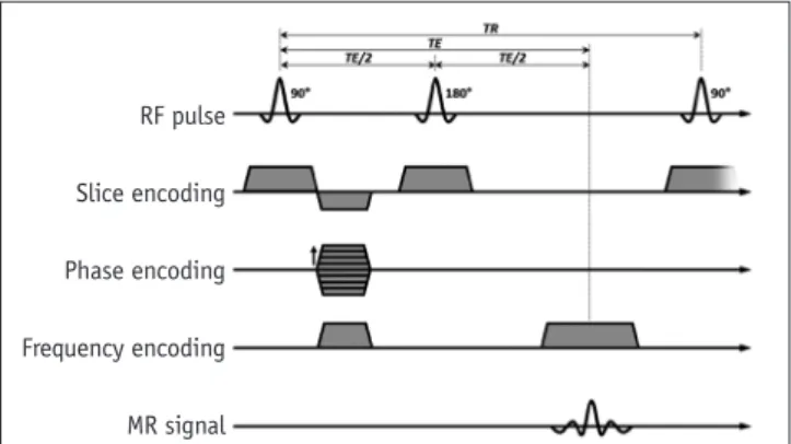
1. Spin-echo
A. Use a 90° excitation pulse and a 180° re-focusing pulse (Fig. 1)
RF pulse
Slice encoding
Phase encoding
Frequency encoding
MR signal
Fig. 1. Spin echo sequence. RF = radio frequency, TE = time of echo, TR = time of repetition
B. Advantages
1) Robust to off-resonance effects
2) Flexible to obtain different contrasts using various time of echo (TE) and time of repetition (TR) C. Disadvantages
1) Long acquisition time 2) Limited temporal resolution 3) Sensitive to motion and flow D. Fast spin-echo (FSE)
1) Acquisition times shortened by using a multi-echo approach (Fig. 2)
2) Turbo spin-echo (TSE), FSE, or rapid acquisition with relaxation enhancement
2. Gradient-echo (GRE)
A. Use a low flip angle and gradient pulses
B. Advantage: faster image acquisition than spin-echo sequences
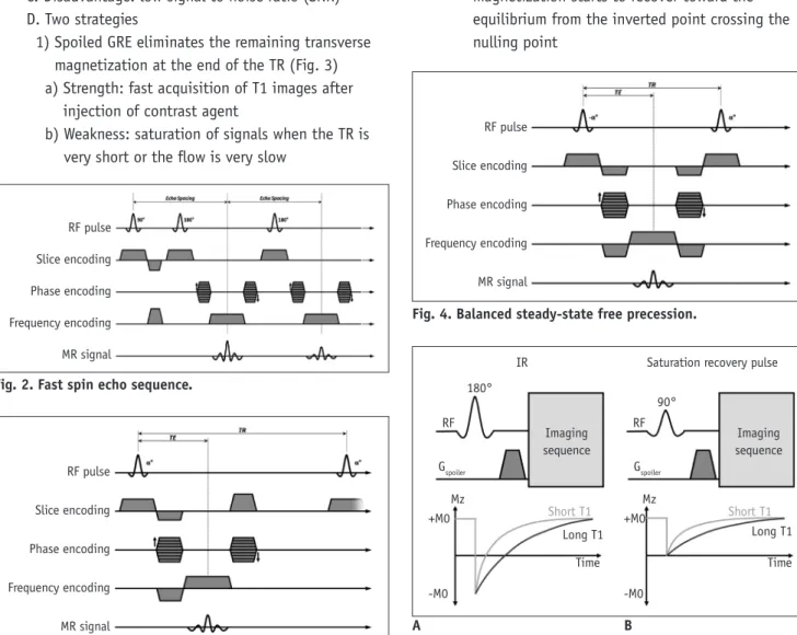
C. Disadvantage: low signal to noise ratio (SNR) D. Two strategies
1) Spoiled GRE eliminates the remaining transverse magnetization at the end of the TR (Fig. 3) a) Strength: fast acquisition of T1 images after
injection of contrast agent
b) Weakness: saturation of signals when the TR is very short or the flow is very slow
2) Balanced steady-state free precession (SSFP) refocuses and reuses the remaining transverse magnetization at the end of the TR (Fig. 4) a) Strengths
• Signal strength mostly unaffected by blood flow
• Rapid image acquisition with a high contrast to noise ratio (CNR)
• Bright vessel and cardiac chamber without a contrast agent
b) Weakness: sensitive to the off-resonance effect, causing dark band artifacts
E. Popular form of CMR due to short acquisition time (better temporal resolution)
3. Preparation pulses A. Inversion pulses
1) Invert the longitudinal magnetization (Fig. 5A) 2) After an inversion pulse, longitudinal
magnetization starts to recover toward the equilibrium from the inverted point crossing the nulling point
RF pulse
Slice encoding
Phase encoding
Frequency encoding
MR signal
Fig. 3. Spoiled gradient echo sequence.
Fig. 2. Fast spin echo sequence.
RF pulse Slice encoding Phase encoding Frequency encoding MR signal
RF pulse
Slice encoding
Phase encoding
Frequency encoding
MR signal
Fig. 4. Balanced steady-state free precession.
Fig. 5. Preparation pulses.
A. Inversion recovery pulse (IR). B. Saturation recovery pulse.
+M0
-M0
+M0
-M0 Short T1
Long T1 Time
Mz Mz
Time Imaging
sequence
Imaging sequence IR
180°
RF
Gspoiler Gspoiler
RF 90°
Saturation recovery pulse
Long T1 Short T1
A B
3) Can be used to null the signal of selective objects, such as water, fat, blood, or the myocardium B. Saturation pulses
1) Saturate the longitudinal magnetization to null a net magnetization (Fig. 5B)
2) After a saturation pulse, longitudinal magnetization starts to recover toward the equilibrium
4. Echo-planar imaging (EPI)
A. Acquires multiple echoes per excitation B. Can be used with TSE or GRE
II. Cardiac MRI sequences (Table 1)
1. Spin echo: morphology, anatomy, tumor, etc.
2. Gradient echo: cine, perfusion, late gadolinium enhancement (LGE), MR coronary angiography (MRCA) A. Spoiled gradient echo: perfusion, LGE, 3D MRCA
with 3.0 tesla (T)
B. Balanced SSFP: 2D cine, 3D MRCA with 1.5T 3. Inversion recovery: LGE, T1 mapping (Modified look-
locker inversion recovery, MOLLI)
4. Saturation pulse: first-pass perfusion, fat saturation pulses, T1 mapping (Saturation recovery single-shot acquisition, SASHA)
Imaging Plane
The heart has its own unique axis. CMR should be performed based on the exact planes that meet the purpose of imaging. Even though recent MR machines provide a support system for the CMR imaging plane, clinicians should be familiar with various image axes for accurate imaging interpretation.
Basic Planes
I. Left ventricle (LV) 2-chamber view, LV 4-chamber view, LV short axis view
1. Scout imaging or localizer imaging
A. Multi-stack transaxial, coronal, and sagittal images should be obtained
2. Vertical long axis image (Supplementary Fig. 1) A. Obtained from the transaxial localizer
1) Orthogonal to a transaxial scout image at the level of the mitral valve (MV) and tricuspid valve (TV) 2) Aligned through the apex and center of the MV 3. Horizontal long axis (Supplementary Fig. 2)
A. Obtained from vertical long axis images
1) Orthogonal to the end-systolic vertical long axis image
2) Aligned through the apex and center of the MV 4. Short axis image (Supplementary Fig. 3)
A. Obtained from vertical long axis images and horizontal long axis images
1) Simultaneously orthogonal to vertical long axis images and horizontal long axis images 2) Perpendicular to the interventricular septum 3) Covers the whole ventricle from the MV to the LV
apex at the diastolic phase
5. Four-chamber view (Supplementary Fig. 4) A. Obtained from vertical long axis images and the
short axis view
1) Orthogonal to the vertical long axis images passing through the LV apex and center of the MV
2) Aligned through the center of the LV chamber and lower corner of the right ventricle (RV) border on short axis images
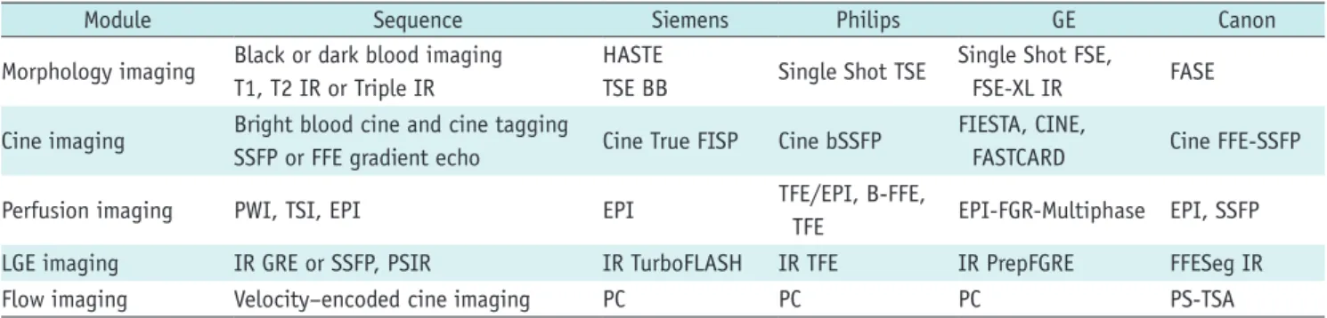
Table 1. Routine Cardiac MRI Sequence Terminology (Vendor)
Module Sequence Siemens Philips GE Canon
Morphology imaging Black or dark blood imaging T1, T2 IR or Triple IR
HASTE
TSE BB Single Shot TSE Single Shot FSE,
FSE-XL IR FASE
Cine imaging Bright blood cine and cine tagging
SSFP or FFE gradient echo Cine True FISP Cine bSSFP FIESTA, CINE,
FASTCARD Cine FFE-SSFP
Perfusion imaging PWI, TSI, EPI EPI TFE/EPI, B-FFE,
TFE EPI-FGR-Multiphase EPI, SSFP
LGE imaging IR GRE or SSFP, PSIR IR TurboFLASH IR TFE IR PrepFGRE FFESeg IR
Flow imaging Velocity–encoded cine imaging PC PC PC PS-TSA
BB = black blood, bSSFP = balanced steady-state free precession, EPI = echo planar imaging, FASE = single-shot turbo spin echo, FFE- SSFP = fast field echo-steady state free precession, FGR = fast gradient recalled acquisition, FGRE = fast gradient echo, FIESTA = fast imaging employing steady-state acquisition, FISP = fast imaging with steady state precession, FLASH = fast low angle shot, FSE = fast spin echo, FSE-XL = fast spin echo-accelerated, GRE = gradient echo, HASTE = half-Fourier acquisition single-shot turbo spin-echo, IR = inversion recovery, LGE = late gadolinium enhancement, PC = phase contrast, PS = phase shift, PSIR = phase-sensitive inversion-recovery, PWI = perfusion weighted image, TSA = time-shift analysis, TSE = turbo spin echo, TSI = time-signal intensity
6. Two-chamber view (Supplementary Fig. 5)
A. Obtained from the 4-chamber view and short axis images
1) Orthogonal to the 4-chamber view, passing through the LV apex and the center of the MV 2) Passing through the mid-LV chamber in the short
axis view, parallel to the ventricular septum II. LV 3-chamber view and LV outflow tract (LVOT) long
axis
1. LV 3-chamber view (Supplementary Fig. 6) A. Obtained from the basal short axis view
1) Parallel to the long axis view 2) Bisecting MV and apex 3) Bisecting LVOT
2. LVOT long axis view (Supplementary Fig. 7) A. Obtained from a true axial scout image
1) Slice through the aortic root toward the LV apex III. RV
1. RV short axis (Supplementary Fig. 8) A. Obtained from the RV 2-chamber view and
4-chamber view
1) Orthogonal to the RV 2-chamber view and 4-chamber view
2) Perpendicular to the interventricular septum 3) Covers the whole ventricle from the TV to the RV
apex at the diastolic phase
2. Right ventricle outflow tract (RVOT) view (Supplementary Fig. 9)
A. Obtained from an axial scout image
1) Slice through the center of the main pulmonary artery (MPA) and the RV apex
Specific Planes
I. MV view (Supplementary Fig. 10)
1. Can be obtained from the 2-chamber view and 4-chamber view
A. Plane is parallel to the MV in the middle of the MV II. TV (Supplementary Fig. 11)
1. Can be obtained from the 2-chamber view and 4-chamber view
A. Plane is parallel to the TV in the middle of the TV III. Aortic valve (AV) view (Supplementary Fig. 12)
1. Can be obtained from the 3-chamber and LVOT views A. Plane is parallel to the AV just above the AV IV. Pulmonic valve (PV) view
1. Can be obtained from the two orthogonal RVOT views A. Plane is parallel to the PV just above the PV
V. MPA view (Supplementary Fig. 13)
1. Can be obtained from two orthogonal views, which are parallel to the MPA
2. Plain is perpendicular to the MPA flow
VI. Right pulmonary artery (RPA) and left pulmonary artery (LPA) views (Supplementary Fig. 14)
1. Plain is perpendicular to the RPA or LPA flow, 1–1.5 cm distal to the MPA bifurcation
Special Considerations and Patient Safety
Field Strength Considerations I. The popularity of 3T CMR
1. 3T MR applications become increasingly used.
Furthermore, many new MR-conditional devices can be used in 3T
2. Advantages A. Increased SNR
B. Increased spatial and/or temporal resolution 3. Weaknesses
A. Increase in inhomogeneities of the radio-frequency (RF) excitation field
B. Increase in the effect of magnetic susceptibility artifacts
C. Increase in the specific absorption rate (SAR) II. Safety
1. No definite safety guideline for performing 3T MRI in patients with a cardiac implantation electronic device (CIED)
2. Careful 3T MRI is necessary, including pre-MRI reprogramming of the device monitoring, supervision, and follow-up
III. RF exposure 1. SAR
A. RF energy absorbed by the body B. Measured in watts per kilogram (W/kg) C. Depends on patient size and weight 2. B1+RMS
A. Root mean square (RMS) of the time-averaged B1+
magnetic field
B. Not patient-dependent, but related to pulse sequences
C. Can be used for implant heating 3. Ways to reduce SAR and B1+RMS
A. Higher degrees of parallel imaging
B. Refocusing flip-angle modulation techniques 1) Frequency-selective inversion-recovery
2) Reduction of flip angle
IV. CMR at 3T influences the performance of several sequences
CMR at 3T requires protocol optimization, careful shimming, and adjustment of the RF pulses to prevent artifacts
1. Improvements: first-pass perfusion, MR angiography, coronary imaging, myocardial tagging, MR
spectroscopy, and fat saturation
2. Equivalent to 1.5T: LGE, flow quantification, and black-blood imaging
3. Considerable limitation: SSFP
4. Main challenges: B0 inhomogeneities, B1 inhomogeneities, off-resonance band artifacts, susceptibility effects, and chemical shift artifacts
Devices
I. CIED in MRI machines 1. Common clinical situation
2. Historically regarded as a contraindication but no longer an absolute contraindication to MRI 3. Adverse interactions
A. Device failure, lead failure, heating, force, torque
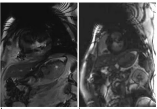
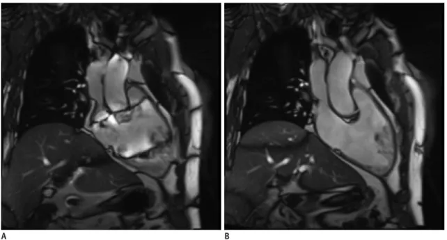
B. Magnetic susceptibility artifacts (Fig. 6) 4. MR-conditional CIED
A. CMR is possible under the adequate workflow protocol
B. Consider the device, device insertion duration, scan region, battery power, MR system, and sequences C. Need cooperation between cardiologists and
radiologists
D. MR safety information on the websites
1) Medtronic: https://www.medtronic.com/us-en/
healthcare-professionals/mri-resources.html 2) Boston Scientific: http://www.bostonscientific.
com/en-US/customer-service/mri-information.html 3) MRI safety.com: http://www.mrisafety.com 5. MR-non-conditional CIED
A. Not recommended
B. Can be performed at 1.5T under the supervision of a physician and radiologist, if benefits outweigh the overwhelming risks
6. MR-conditional CIED checklists are provided in Appendix 2
7. Recommendations to minimize artifacts from a CIED A. Sufficient distance (> 6 cm) between the CIED pulse
Fig. 6. Magnetic susceptibility artifact by cardiac implantable electronic device.
Cine image (A) and LGE image (B) show significant magnetic susceptibility artifact caused by cardiac implantable electronic device. LGE = late gadolinium enhancement
A B
generator and the heart or CIED pulse generator in the right chest wall
B. Spoiled GRE sequence with wide bandwidth rather than SSFP
C. Change the center offset frequency using the SSFP sequence
D. Long-axis plane for the mid to apical LV and short- axis plane for the LV base
Drugs
I. Gadolinium-based MRI contrast agents
1. Shorten the relaxation times of nuclei within the body
2. Nephrogenic systemic fibrosis A. A rare and serious syndrome
B. Fibrosis of skin, joints, eyes, and internal organs C. High-risk patients
1) Chronic kidney disease stages 4 and 5 (glomerular filtration rate < 30 mL/min/1.73 m2)
2) Acute renal failure or chronic liver disease D. The gadolinium-containing contrast agents can be
divided into three risk groups 1) Safest: macrocyclic structure
a) Gadoterate, gadobutrol, and gadoteridol 2) Intermediate: an ionic linear structure
a) Gadopentetate, gadobenate, gadoxetate, and gadofosveset
3) Most risky: linear non-ionic structure a) Gadodiamide and gadoversetamide 3. Brain deposition
A. Gadolinium can lodge in the deep nuclei of the brain, especially when injected repeatedly B. Macrocyclic agents might accumulate less than
linear agents
C. No reliable data about clinical effects or significance 4. The Korean Food and Drug Administration
recommends the use of a gadolinium-based MRI contrast agent with a macrocyclic structure. In Korea, the supply of gadopentetate, gadodiamide, and gadoversetamide has been discontinued. In the EU, the use of gadolinium-based MRI contrast agents with a linear structure is prohibited
II. Pharmacologic stressors and vasodilators 1. Dobutamine
A. Inotrope
1) Directly stimulates β1 receptors in the sympathetic nervous system
2) Increases myocardial oxygen demand → promotes myocardial ischemia
3) Increases heart rate, blood pressure, and contractility similar to exercise
4) Half-life: approximately 2 minutes 5) Typical maximum dose: 40 µg/kg/min B. Contraindications
1) Unstable angina pectoris
2) Severe systemic arterial hypertension (≥ 220/120 mm Hg)
3) Severe aortic stenosis
4) Obstructive hypertrophic cardiomyopathy with hemodynamic significance
5) Uncontrolled cardiac arrhythmias 6) Uncontrolled congestive heart failure 7) Endocarditis
8) Myocarditis or pericarditis
9) Family history of sudden cardiac death 10) Aortic dissection
11) High-grade aortic aneurysm
12) Mobile thrombus in LV or left atrium 2. Adenosine, dipyridamole, and regadenoson
A. Vasodilators
1) Promote systemic arterial vasodilation to bring about a super-physiologic increase in vascular flow 2) Emphasize the difference between normal coronary
arteries (which can dilate) and a stenosed coronary artery (which is already maximally dilated)
B. Adenosine
1) Acts on the vascular smooth muscle surface to cause vasodilation
2) Binds non-selectively to A1, A2A, A2B, and A3 a) Activation of A2A → coronary vasodilation b) Activation of A1, A2B, and A3 → bronchospasm,
atrioventricular block, etc. (unwanted side effects)
3) Dose: 0.14 mg/kg/min 4) Half-life: 10–30 seconds
5) Competitive inhibitors of adenosine
a) Aminophylline, theophylline, and other xanthine- containing foods, such as coffee, tea, cocoa products, and soft drinks
b) Should be restricted for approximately 24 hours prior to the study
6) Contraindications
a) Hypersensitivity to adenosine
b) Bronchoconstriction or bronchospastic disease
c) 2nd or 3rd degree atrioventricular block
d) Significant sinus bradycardia (resting heart rate <
45 bpm)
e) Systolic blood pressure less than 90 mm Hg f) Severe arterial hypertension
g) Myocardial infarction within 3 days
h) Disease requiring the regular use of inhalers for asthma, sinus arrhythmia, stenotic valvular disease, or carotid artery stenosis
7) Antidote: intravenous (IV) aminophylline C. Dipyridamole
1) Inhibits the cellular uptake and metabolism of adenosine → increases the interstitial adenosine concentration
D. Regadenoson
1) Higher selectively for A2A activation than adenosine
2) Dose: 0.4 mg single injection 3) Half-life: 2–3 minutes 4) Precautions
a) Restriction of products containing xanthine for 24–36 hours before the test
b) No caffeine for at least 6 hours, but ideally 24 hours, before the test
c) No tobacco for 4 hours before the test 3. Please use checklists to ensure patient safety and
image quality (2).
Exam Modules
Cine Imaging
I. Purpose: to assess cardiac wall motion II. Sequences
1. Balanced SSFP or spoiled GRE
2. Real time cine (patients with poor breath holding or arrhythmia)
III. Image parameters
1. ECG gating: retrospective rather than prospective 2. Slice thickness: 6–8 mm (no gap)
3. Temporal resolution: ≤ 45 ms between phases 4. Acquired time frames: 25–30 frames/R-R interval 5. Parallel imaging: used as available
IV. Tips
1. Uses retrospective gating rather than prospective triggering
A. Acquisition of the entire cardiac cycle B. Can select the appropriate segment C. Arrhythmia rejection
2. Banding artifacts (Fig. 7)
A. More severe on 3T MR than 1.5T due to B0 field inhomogeneity
B. Solutions 1) Shimming
a) Volume shim centered on the left ventricle b) During shimming, minimize motion (e.g., breathe
shallowly)
Fig. 7. Banding artifact.
A. Cine image of 2-chamber right ventricle view shows severe banding artifact which hampers appropriate interpretation. B. After cardiac shimming and TR adjustment, image quality is improved without banding artifact.
A B
2) Shortest TR
3) The center frequency is aligned closely with the water resonance frequency
V. Dobutamine stress test
1. To evaluate the viability and contractile reserve 2. Avoid beta-blockers and nitrates
3. Infusion dose A. Start: 10 µg/kg/min
B. Increase: 10 µg/kg/min every 3 minutes C. Infusion time: 5–10 minutes
D. Target heart rate: 85% of (220 - age)
E. Option: if heart rate response is poor, add 0.3 mg of atropine in fractional doses of up to 2 mg
1) Contraindications for atropine a) Advanced heart block b) Glaucoma
c) Pyloric stenosis d) Obstructive uropathy e) Myasthenia gravis
4. Caution: indications for stopping the test
A. New wall motion abnormality or wall thickening abnormality
B. Systolic blood pressure > 240 mm Hg or diastolic blood pressure > 120 mm Hg
C. Systolic blood pressure decrease of 20 mm Hg or greater below baseline
D. Severe chest pain or other intractable symptoms E. Complex cardiac arrhythmias or reaching peak heart
rate
Perfusion Imaging
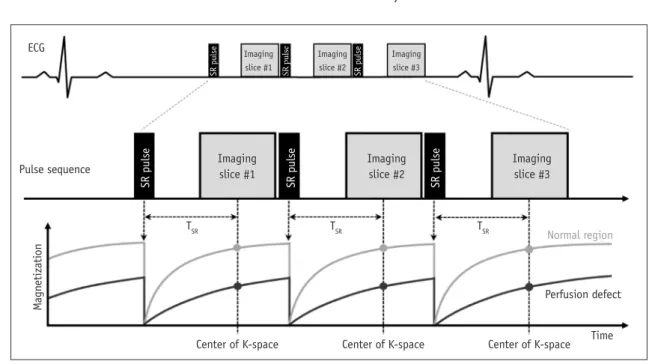
I. Purpose: to evaluate myocardial perfusion (ischemia) II. Sequences: saturation-recovery imaging with GRE-EPI
hybrid, GRE, or SSFP readout (Fig. 8) III. Image parameters
1. Slice thickness: 8–10 mm 2. In-plane resolution: < 3 mm
3. Two-fold acceleration and readout temporal resolution: < 100–125 ms (shorter if available) 4. Parallel imaging (if available)
IV. Scan protocol
1. Scout imaging: same as LV structure and function 2. Stress myocardial perfusion
A. Slices: at least three short-axis slices per heartbeat at the LV base, mid, and apical levels
1) To reduce motion artifacts, obtain the apical slice first and the basal slice last during the cardiac cycle
2) If possible, add one slice to the 4-chamber or 2-chamber views
B. Do a rehearsal scan without contrast or vasodilator injection (dry run) to check the image quality and correct the parameters
1) At the end expiration 2) 5–10 phases to check
C. Vasodilator infusion: adenosine stress perfusion 1) Place two IV catheters in each arm
a) 20 G IV catheter for contrast material injection b) 20–22 G IV catheter for adenosine infusion
ECG
TSR
Center of K-space Center of K-space Center of K-space Time Normal region
Perfusion defect
TSR TSR
Pulse sequence Imaging
slice #1
Imaging slice #1
Imaging slice #2
Imaging slice #3
Imaging slice #2
Imaging slice #3
SR pulse
Magnetization SR pulse SR pulse
SR pulse SR pulse SR pulse
Fig. 8. First pass perfusion sequence. ECG = electrocardiogram, SR = saturation, TSR = SR time
2) Adenosine infusion a) 0.14 mg/kg/minutes
b) 4–6 minutes continuous infusion
c) When the gadolinium has passed through the LV myocardium, the adenosine infusion should be stopped after imaging 50–60 heartbeats d) Please check the drug section (adenosine,
dipyridamole, and regadenoson)
3) Antidote: aminophylline, 125 mg in 50 mL normal saline by IV infusion for 5–6 minutes
a) Use if chest pain or shortness of breath occurs D. Gadolinium contrast agent
1) 0.05–0.1 mmol/kg, 3–7 mL/s during the last minute of adenosine infusion
2) Saline flush: at least 30 mL (3–7 mL/s) E. Breath-hold: during the early phases of contrast
infusion, before contrast reaches the LV cavity F. Readout for 40–60 heartbeats, in which time
contrast will have passed through the LV myocardium 3. LV function mode between a stress test and resting
test while waiting for contrast washout 4. Rest myocardial perfusion imaging
A. After a washout period of at least 10 minutes for the gadolinium from the stress perfusion imaging to pass
B. Same protocol for stress perfusion (except for vasodilator infusion)
5. LGE V. Tips
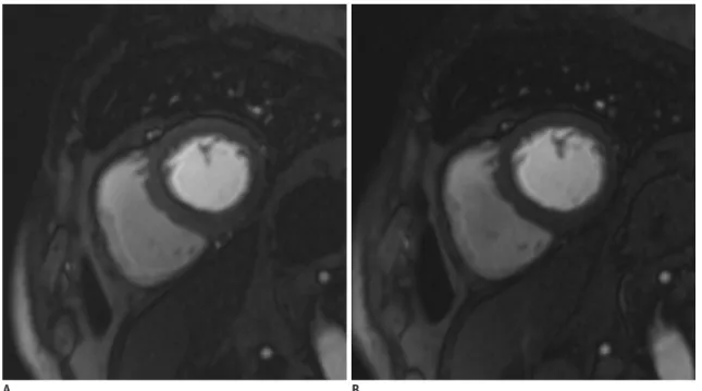
1. Dark rim artifact (Fig. 9)
A. Most common artifact with the perfusion module B. Commonly occurs at the subendocardial border C. Can be confused with a perfusion defect D. Related factors
1) Limited spatial resolution 2) Cardiac motion
3) Partial volume artifact
4) Higher concentration of the contrast agent E. Solutions
1) Low dose of contrast medium
2) High spatial resolution (in the phase encoding direction)
3) Thin slice thickness 4) High field strength 5) Fast imaging
2. Use the checklists for the adenosine stress test (2)
LGE Imaging
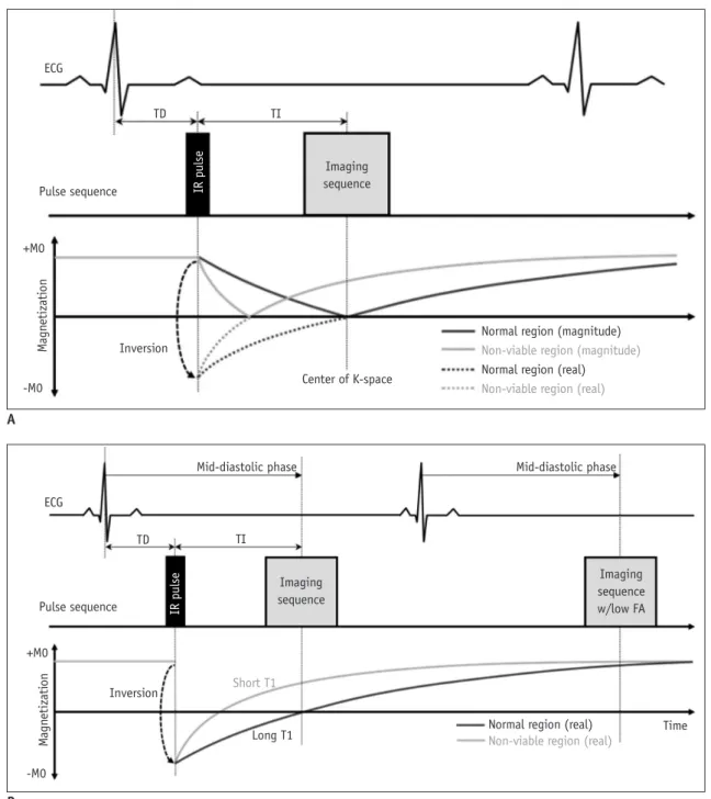
I. Purpose: to evaluate myocardial viability II. Sequences (Fig. 10)
1. Patients with sufficient respiratory support: 2D segmented inversion recovery GRE or SSFP, phase- sensitive inversion-recovery (PSIR), and 3D sequences 2. Patients with poor breath holding: single-shot
Fig. 9. Dark rim artifact during perfusion magnetic resonance imaging.
Subendocardial dark rims are seen at basal septum on both stress (A) and rest (B) perfusion images.
A B
imaging (SSFP readout) III. Image parameters
1. Acquisition duration per R-R interval: below 200 ms 2. Slice thickness and slices at the identical location:
same as for cine imaging (short- and long-axis views) IV. Scan protocol
1. Axis: same as cine imaging
2. Contrast medium injection: 0.1–0.2 mmol/kg gadolinium
3. Wait at least 10 minutes after administration 4. Set inversion time to null normal myocardium using
time of inversion (TI) map V. Tips
1. I f the inversion time is inaccurate, use the PSIR sequences
2. If the image quality is poor due to motion artifacts or poor breath holding, use single shot LGE (Fig. 11) 3. Ghosting artifacts with long T1 tissue
Fig. 10. LGE sequences.
Sequences of LGE with magnitude IR (A) and phase-sensitive inversion-recovery (B). FA = flip angle, TD = trigger delay, TI = inversion time ECG
Pulse sequence
Inversion
Mid-diastolic phase Mid-diastolic phase
Long T1 Time
Short T1 Imaging sequence
Imaging sequence w/low FA
TD TI
Normal region (real) Non-viable region (real) +M0
-M0
Magnetization IR pulse
ECG
Pulse sequence
Inversion
Center of K-space Imaging sequence
TD TI
Normal region (magnitude) Non-viable region (magnitude) Normal region (real) Non-viable region (real) +M0
-M0
Magnetization IR pulse
A
B
A. Pericardial effusion, cerebrospinal fluid, and the silicon bag can cause ghosting artifacts
1) This ghosting artifact is not a motion artifact 2) Solution: single shot LGE
Flow Imaging
I. Purpose: to measure flow velocity and volume 1. Measure pulmonary blood flow (Qp)
2. Measure systemic blood flow (Qs)
3. Pulmonary-to-systemic flow ratio (Qp:Qs) 4. Calculate regurgitant fractions
5. Calculate the valve area
6. Calculate the aortopulmonary collateral flow II. Sequences
1. Velocity–encoded cine gradient echo
A. Magnitude images provide anatomic information B. Phase images provide velocity information III. Image parameters
1. ECG gating: retrospective gating includes the entire diastolic portion of the cardiac cycle
2. Slice thickness: 5–8 mm
3. In-plane resolution: at least 1/10 of the vessel diameter, 1.3–2.0 mm
4. Velocity encoding sensitivity (VENC): adapted to the expected velocities
5. Acquired time frames: 25–30 frames/R-R interval 6. Average number of signals: 2–3
IV. Tips
1. Plane: perpendicular to the vessel and distal to valve leaflet tips of interest
A. Deviations of more than 15° cause significant errors in the peak velocity and flow rate
2. VENC (Fig. 12)
A. Adjust 10–20% higher than expected peak velocities B. A too-low velocity causes aliasing
C. A too-high velocity causes noise and inaccurate measurements
D. Usual peak velocities
1) Main pulmonary artery: 60–120 cm/s 2) Right/left pulmonary artery: 60–120 cm/s 3) Ascending aorta: 100–160 cm/s
3. TE: as short as possible 4. Spatial resolution
A. Sufficient spatial resolution to prevent significant partial volume effects
B. Recommendation: more than 3 pixels across the diameter or more than 8 pixels in the cross-section of the region of interest
5. Temporal resolution
A. Sufficient temporal resolution to prevent a smooth pulsatile flow curve and cause inaccuracies
B. Recommendation: acquire a minimum of 20 non- interpolated images during the cardiac cycle Fig. 11. Better image quality of single shot LGE in patient with poor breath holding.
LGE image with two-dimensional segmented inversion recovery gradient-echo (A) in patient with poor breath holding shows poor image quality with significant motion artifact. Single shot LGE (B) shows much improved image quality with less motion artifact.
A B
Morphology Imaging
I. Purpose: to delineate anatomic structures II. Sequences
1. Spin-echo sequence: FSE or TSE techniques A. TSE black blood preparation pulses: two 180° RF
inversion pulses followed by a delay before the spin echo pulse sequence
B. Strength: high CNR
C. Weakness: sensitive to motion artifacts
2. Half-Fourier acquisition single-shot turbo spin-echo (HASTE)
3. Dark blood GRE: less sensitive to artifacts or motion III. Image parameters
1. Slice thickness: 6–8 mm (no gap)
2. Black blood inversion preparation pulse: 20 mm 3. Echo train length: 15–20
IV. Tips
1. Breath-hold, pre-contrast segmented FSE or TSE imaging with double inversion recovery: sequence with good CNR preferred
2. If motion artifact is significant with FSE or TSE, try HASTE or dark blood GRE
3. Optimizing readout time by acquiring multiple images
throughout the diastole is essential to minimizing dropout artifacts
A. T2 weighted image (T2WI) is prone to be
inhomogeneous with readout time changes, which could hamper the appropriate interpretation B. T2 map could be better than T2WI for evaluating
myocardial edema
Tissue Characterization: T1 Mapping
I. Purpose: to evaluate the absolute T1 value of the myocardium
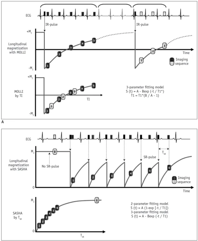
II. Sequences (Fig. 13)
1. Inversion recovery-based protocol A. MOLLI or shortened MOLLI B. Strength
1) Good SNR, good image quality 2) Better precision than SASHA C. Weakness
1) Sensitive to heart rate
2. Saturation recovery-based protocol A. SASHA
B. Strength
1) Better accuracy than MOLLI Fig. 12. VENC effect on phase-contrast flow imaging.
Very low VENC factor (A, VENC factor = 90 cm/s) causes aliasing on phase contrast flow image of ascending aorta. Usual peak of ascending aorta is 100–160 cm/s (B, VENC factor = 130 cm/s; C, VENC factor = 160 cm/s). Very high VENC factor (D, VENC factor = 190 cm/s) causes noise and inaccurate measurement. VENC = velocity encoding sensitivity
A
C
B
D
2) Insensitive to heart rate C. Weakness
1) High image noise
3. Combined: saturation pulse–prepared, heart-rate- independent inversion recovery (SAPPHIRE) sequence III. Image parameters
1. Slice thickness: 6–8 mm
2. In-plane resolution: less than 2 mm 3. Acquisition time
A. 9–17 heartbeats
B. Various, depending on the used T1 mapping sequences
Fig. 13. T1 mapping sequences.
T1 mapping sequences with MOLLI (A) and SASHA (B). MOLLI = modified look-locker inversion recovery, SASHA = saturation recovery single-shot acquisition
ECG
Longitudinal magnetization
with MOLLI +MZ
IR-pulse
TI
Time Imaging sequence
3-parameter fitting model S (t) = A - Bexp (-t / T1*)
T1 = T1*(B / A - 1) IR-pulse
-MZ
-MZ +MZ
MOLLI by TI
ECG
Longitudinal magnetization
with SASHA MZ
MZ
No SR-pulse
TSR
Time Imaging sequence
2-parameter fitting model S (t) = A (1-exp [-t / T1]) 3-parameter fitting model S (t) = A - Bexp (-t / T1)
SR-pulse TSR
0 0
SASHA by TSR A
B
IV. Tips
1. Need site-specific normative values
A. Normative mapping values can be affected by various factors, including field strength, vendor, sequence, contrast regime, and patient population (age/sex)
1) Reported normal values for native T1 of normal myocardium
a) 1.5T: 930–1052 ms b) 3T: 1052–1158 ms
2. Native T1 and extracellular volume (ECV) fraction:
preferred to partition coefficient and post contrast T1 3. Contrast media injection
A. Bolus-only protocol for ECV measurement 1) Sufficient for most myocardial ECV applications 2) A delay of at least 15 minutes is recommended for
dynamic equilibrium V. Scan protocol (Fig. 14)
1. Native T1 mapping is performed prior to contrast 2. Post-contrast T1 mapping: perform >15 minutes after
administration of contrast agent
3. Blood sampling is required for ECV assessment
Tissue Characterization: T2 Mapping
I. Purpose: to evaluate the absolute T2 value of the myocardium
II. Sequences
1. Single shot SSFP: T2-prepared single-shot SSFP sequence acquired with different T2 prep times III. Image parameters
1. Slice thickness: 6–8 mm
2. In-plane resolution: less than 2 mm 3. Acquisition time: 7 R-R
IV. Tips
1. Obtain prior to contrast administration
Tissue Characterization: T2* Mapping I. Purpose
1. To evaluate the absolute T2* value of the myocardium 2. To assess cardiac iron deposition in diseases such as
thalassemia major II. Sequences
1. Single shot SSFP III. Image parameters
1. Slice thickness: 8–10 mm
2. In-plane resolution: less than 2 mm IV. Tips
1. Obtain prior to contrast administration
Coronary Angiography
I. Purpose: to evaluate coronary artery disease II. Sequences
1. 1.5T
A. SSFP MRCA sequences without injection of
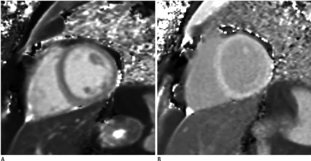
Fig. 14. Native T1 map and post T1 map.
Native T1 map image (A) acquired prior to contrast injection provides pixel-wise absolute native T1 values. Post T1 map image (B) acquired after administration of contrast agent provides pixel-wise post T1 values. Using native T1 values and post T1 values of myocardium and blood cavity and hematocrit value, extracellular volume fraction of myocardium could be calculated.
A B
gadolinium-based contrast agent 2. 3T
A. Gradient-echo sequence with the administration of contrast medium
B. SSFP MRCA—not appropriate due to severe banding artifacts
C. T2 prep-MRCA without contrast enhancement III. Advantages compared to coronary computed
tomography angiography 1. No ionizing radiation 2. No iodine contrast agent 3. Excellent temporal resolution
4. Evaluation of heavily calcified plaques IV. Image parameters
1. Slice thickness: 1–1.5 mm
2. In-plane resolution: 1.0 mm or less 3. Slices
A. 50–80 slices to encompass vessels of interest B. Adjust trigger delay and acquisition window
according to the coronary period
C. Navigator placed over the right hemidiaphragm V. Tips
1. Whole heart MRCA: respiratory gating and ECG gating
2. Vessel targeted MRCA: can reduce imaging time 3. Regular (slow) heartbeat: use mid-diastolic phase 4. Arrhythmia or tachycardia: use the systolic phase 5. Continuous infusion of contrast medium (3T): can
improve SNR VI. Scan protocol
1. LV structure and function module
2. Horizontal long axis images for the imaging period of the right coronary artery
3. MRCA sequence
4. Transaxial slices if desired
Disease/Symptom-Based Protocol
Eighteen expert panel members, 9 cardiologists and 9 radiologists who were familiar with cardiac MRI, completed a questionnaire about the appropriate protocol for a variety of clinical situations (Table 2). To assess each clinical situation, they gave 9 points if a pulse sequence was necessary and 1 point if it was not necessary. If more than half of the panelists in one group voted in the same manner (A: appropriate [7–9]; U: unknown [4–6]; I:
inappropriate [1–3]), it was deemed a consensus. Items without consensus in the first survey reappeared in the
Table 2. Disease/Symptom-Based Protocol, Based on Questionnaire T1 Cine,
LV
Cine, Stress
Cine, RV
Perfusion,
Stress LGE VENC,
Flow T2 T1
Mapping
Suspected/stable coronary artery disease 6 9 7 7 9 9 6 5 7
Acute coronary syndrome 6 8 2 8 3 9 5 7 6
Before coronary revascularization 6 9 7 8 8 9 5 7 7
After coronary revascularization 6 8 7 7 7 9 6 7 6
Heart failure 7 9 5 9 5 9 7 9 9
Valvular heart disease 6 8 4 8 5 7 7 5 7
Infective endocarditis 4 7 3 7 4 5 5 5 4
Hypertrophic cardiomyopathy 7 9 6 9 7 9 7 7 9
Storage disease 7 9 5 9 6 9 6 9 9
Pericardial diseases 7 8 3 9 4 9 6 7 8
Pregnancy 5 7 1 7 3 3 5 3 3
Arterial hypertension 4 4 3 6 3 9 5 3 4
Ventricular arrhythmia 6 9 3 8 5 9 5 4 7
Atrial fibrillation 5 6 3 6 4 6 5 4 5
Peripheral artery diseases 4 6 2 6 3 3 3 3 3
Pulmonary hypertension 5 7 3 9 5 7 7 3 7
Acute pulmonary embolism 3 5 2 7 3 3 3 3 3
Aortic diseases 5 6 1 5 3 4 5 2 3
Non-cardiac surgery: cardiovascular assessment 3 5 3 7 5 5 5 3 3
Grown-up congenital heart disease 7 9 5 9 5 9 8 6 7
Each score given is median. A = appropriate (7–9), U = unknown (4–6), I = inappropriate (1–3). LV = left ventricle, RV = right ventricle, VENC = velocity encoding sensitivity
second survey, after which consensus was reached on all items. Each score given is the median (Table 2).
Supplementary Materials
The Data Supplement is available with this article at https://doi.org/10.3348/kjr.2019.0398.
Conflicts of Interest
The authors have no potential conflicts of interest to disclose.
Acknowledgments
We thank Mun Young Paek, MR physicist (Siemens Healthineers Ltd.), for advising us about MR physics.
ORCID iDs Chul Hwan Park
https://orcid.org/0000-0002-0004-9475 Hwan Seok Yong
https://orcid.org/0000-0003-0247-8932 Yeseul Jo
https://orcid.org/0000-0001-8135-6655 JeongJae Kim
https://orcid.org/0000-0003-0135-3804
REFERENCES
1. Yoon YE, Hong YJ, Kim HK, Kim JA, Na JO, Yang DH, et al. 2014 Korean guidelines for appropriate utilization of cardiovascular magnetic resonance imaging: a joint report of the Korean Society of Cardiology and the Korean Society of Radiology. Korean J Radiol 2014;15:659-688
2. ASCI CCT and CMR Guideline Working Group, Chan CW, Choi BW, Jinzaki M, Kitagawa K, Tsai IC, Yong HS, et al. ASCI 2010 standardized practice protocol for cardiac magnetic resonance imaging: a report of the Asian Society of Cardiovascular Imaging cardiac computed tomography and cardiac magnetic resonance imaging guideline working group. Int J Cardiovasc Imaging 2010;26(Suppl 2):187-202
3. Kramer CM, Barkhausen J, Flamm SD, Kim RJ, Nagel E; Society for Cardiovascular Magnetic Resonance Board of Trustees Task Force on Standardized Protocols. Standardized cardiovascular magnetic resonance (CMR) protocols 2013 update. J Cardiovasc Magn Reson 2013;15:91
4. Woodard PK, Bluemke DA, Cascade PN, Finn JP, Stillman AE, Higgins CB, et al. ACR practice guideline for the performance and interpretation of cardiac magnetic resonance imaging (MRI). J Am Coll Radiol 2006;3:665-676
5. Kramer CM, Barkhausen J, Flamm SD, Kim RJ, Nagel E; Society
for Cardiovascular Magnetic Resonance Board of Trustees Task Force on Standardized Protocols. Standardized cardiovascular magnetic resonance imaging (CMR) protocols, Society for Cardiovascular Magnetic Resonance: Board of Trustees Task Force on standardized protocols. J Cardiovasc Magn Reson 2008;10:35
6. Fratz S, Chung T, Greil GF, Samyn MM, Taylor AM,
Valsangiacomo Buechel ER, et al. Guidelines and protocols for cardiovascular magnetic resonance in children and adults with congenital heart disease: SCMR expert consensus group on congenital heart disease. J Cardiovasc Magn Reson 2013;15:51 7. ASCI Practice Guideline Working Group, Beck KS, Kim JA,
Choe YH, Hian SK, Hoe J, Hong YJ, et al. 2017 Multimodality appropriate use criteria for noninvasive cardiac imaging:
Expert Consensus of the Asian Society of Cardiovascular Imaging. Korean J Radiol 2017;18:871-880
8. Friedrich MG, Larose E, Patton D, Dick A, Merchant N, Paterson I; Canadian Society for CMR. Canadian Society for Cardiovascular Magnetic Resonance (CanSCMR) recommendations for cardiovascular magnetic resonance image analysis and reporting. Can J Cardiol 2013;29:260-265 9. Hundley WG, Bluemke D, Bogaert JG, Friedrich MG, Higgins
CB, Lawson MA, et al. Society for Cardiovascular Magnetic Resonance guidelines for reporting cardiovascular magnetic resonance examinations. J Cardiovasc Magn Reson 2009;11:5 10. Levine GN, Gomes AS, Arai AE, Bluemke DA, Flamm SD, Kanal
E, et al. Safety of magnetic resonance imaging in patients with cardiovascular devices: an American Heart Association scientific statement from the Committee on Diagnostic and Interventional Cardiac Catheterization, Council on Clinical Cardiology, and the Council on Cardiovascular Radiology and Intervention: endorsed by the American College of Cardiology Foundation, the North American Society for Cardiac Imaging, and the Society for Cardiovascular Magnetic Resonance.
Circulation 2007;116:2878-2891
11. Ridgway JP. Cardiovascular magnetic resonance physics for clinicians: part I. J Cardiovasc Magn Reson 2010;12:71 12. Biglands JD, Radjenovic A, Ridgway JP. Cardiovascular
magnetic resonance physics for clinicians: part II. J Cardiovasc Magn Reson 2012;14:66
13. Ferreira PF, Gatehouse PD, Mohiaddin RH, Firmin DN.
Cardiovascular magnetic resonance artefacts. J Cardiovasc Magn Reson 2013;22;15:41
14. Huang SY, Seethamraju RT, Patel P, Hahn PF, Kirsch JE, Guimaraes AR. Body MR imaging: artifacts, k-Space, and solutions. Radiographics 2015;35:1439-1460
15. Saloner D, Liu J, Haraldsson H. MR physics in practice: how to optimize acquisition quality and time for cardiac MR imaging.
Magn Reson Imaging Clin N Am 2015;23:1-6
16. Ibrahim el-SH. Imaging sequences in cardiovascular magnetic resonance: current role, evolving applications, and technical challenges. Int J Cardiovasc Imaging 2012;28:2027-2047 17. Sena L. Cardiac MR imaging: from physics to protocols. Pediatr
Radiol 2008;38 Suppl 2:S185-S191
18. Ginat DT, Fong MW, Tuttle DJ, Hobbs SK, Vyas RC. Cardiac imaging: part 1, MR pulse sequences, imaging planes, and basic anatomy. AJR Am J Roentgenol 2011;197:808-815 19. Nael K, Fenchel M, Saleh R, Finn JP. Cardiac MR imaging:
new advances and role of 3T. Magn Reson Imaging Clin N Am 2007;15:291-300
20. Gimbel JR. Magnetic resonance imaging of implantable cardiac rhythm devices at 3.0 tesla. Pacing Clin Electrophysiol 2008;31:795-801
21. Rajiah P, Bolen MA. Cardiovascular MR imaging at 3 T:
opportunities, challenges, and solutions. Radiographics 2014;34:1612-1635
22. Mangion K, Clerfond G, McComb C, Carrick D, Rauhalammi SM, McClure J, et al. Myocardial strain in healthy adults across a broad age range as revealed by cardiac magnetic resonance imaging at 1.5 and 3.0T: associations of myocardial strain with myocardial region, age, and sex. J Magn Reson Imaging 2016;44:1197-1205
23. Oshinski JN, Delfino JG, Sharma P, Gharib AM, Pettigrew RI.
Cardiovascular magnetic resonance at 3.0 T: current state of the art. J Cardiovasc Magn Reson 2010;12:55
24. Lim J, Park EA, Song YS, Lee W. Single-dose gadoterate meglumine for 3T late gadolinium enhancement MRI for the assessment of chronic myocardial infarction: intra-individual comparison with conventional double-dose 1.5T MRI. Korean J Radiol 2018;19:372-380
25. Min JY, Ko SM, Song IY, Yi JG, Hwang HK, Shin JK.
Comparison of the diagnostic accuracies of 1.5T and 3T stress myocardial perfusion cardiovascular magnetic resonance for detecting significant coronary artery disease. Korean J Radiol 2018;19:1007-1020
26. Roguin A, Schwitter J, Vahlhaus C, Lombardi M, Brugada J, Vardas P, et al. Magnetic resonance imaging in individuals with cardiovascular implantable electronic devices. Europace 2008;10:336-346
27. Sierra M, Machado C. Magnetic resonance imaging in patients with implantable cardiac devices. Rev Cardiovasc Med 2008;9:232-238
28. Burke PT, Ghanbari H, Alexander PB, Shaw MK, Daccarett M, Machado C. A protocol for patients with cardiovascular implantable devices undergoing magnetic resonance imaging (MRI): should defibrillation threshold testing be performed post-(MRI). J Interv Card Electrophysiol 2010;28:59-66 29. Halshtok O, Goitein O, Abu Sham’a R, Granit H, Glikson M,
Konen E. Pacemakers and magnetic resonance imaging: no longer an absolute contraindication when scanned correctly.
Isr Med Assoc J 2010;12:391-395
30. Cronin EM, Wilkoff BL. Magnetic resonance imaging conditional pacemakers: rationale, development and future directions. Indian Pacing Electrophysiol J 2012;12:204-212 31. Miller JD, Nazarian S, Halperin HR. Implantable electronic cardiac devices and compatibility with magnetic resonance imaging. J Am Coll Cardiol 2016;68:1590-1598
32. Shulman RM, Hunt B. Cardiac implanted electronic devices
and MRI safety in 2018-the state of play. Eur Radiol 2018;28:4062-4065
33. Hsu C, Parker G, Puranik R. Implantable devices and magnetic resonance imaging. Heart Lung Circ 2012;21:358-363
34. Strach K, Meyer C, Schild H, Sommer T. Cardiac stress MR imaging with dobutamine. Eur Radiol 2006;16:2728-2738 35. Ordovas KG, Higgins CB. Delayed contrast enhancement on
MR images of myocardium: past, present, future. Radiology 2011;261:358-374
36. Kim PK, Hong YJ, Im DJ, Suh YJ, Park CH, Kim JY, et al.
Myocardial T1 and T2 mapping: techniques and clinical applications. Korean J Radiol 2017;18:113-131
37. Hamdy A, Ishida M, Sakuma H. Cardiac MR assessment of coronary arteries. Cardiovasc Imaging Asia 2017;1:49-59 38. Montant P, Sigovan M, Revel D, Douek P. MR imaging
assessment of myocardial edema with T2 mapping. Diagn Interv Imaging 2015;96:885-890
39. Kim HW, Van Assche L, Jennings RB, Wince WB, Jensen CJ, Rehwald WG, et al. Relationship of T2-weighted MRI myocardial hyperintensity and the ischemic area-at-risk. Circ Res 2015;117:254-265
40. Srichai MB, Lim RP, Wong S, Lee VS. Cardiovascular applications of phase-contrast MRI. AJR Am J Roentgenol 2009;192:662-675
41. Lotz J, Meier C, Leppert A, Galanski M. Cardiovascular flow measurement with phase-contrast MR imaging: basic facts and implementation. Radiographics 2002;22:651-671 42. Verhaert D, Thavendiranathan P, Giri S, Mihai G, Rajagopalan
S, Simonetti OP, et al. Direct T2 quantification of myocardial edema in acute ischemic injury. JACC Cardiovasc Imaging 2011;4:269-278
43. Goo HW. Comparison between three-dimensional navigator- gated whole-heart MRI and two-dimensional cine MRI in quantifying ventricular volumes. Korean J Radiol 2018;19:704- 714
44. Wang L, Chen Y, Zhang B, Chen W, Wang C, Song L, et al.
Self-gated late gadolinium enhancement at 7T to image rats with reperfused acute myocardial infarction. Korean J Radiol 2018;19:247-255
45. Karimi S, Pourmehdi M, Naderi M. Re: prediction of the left ventricular functional outcome by myocardial extracellular volume fraction measured using magnetic resonance imaging:
methodological issue. Korean J Radiol 2019;20:1001-1002 46. Cui C, Yin G, Lu M, Chen X, Cheng S, Li L, et al. Retrospective
electrocardiography-gated real-time cardiac cine MRI at 3T:
comparison with conventional segmented cine MRI. Korean J Radiol 2019;20:114-125
47. Sakuma H. Magnetic resonance imaging for ischemic heart disease. J Magn Reson Imaging 2007;26:3-13
48. Childs H, Friedrich MG. Cardiovascular magnetic resonance imaging in myocarditis. Prog Cardiovasc Dis 2011;54:266-275 49. Florian A, Jurcut R, Ginghina C, Bogaert J. Cardiac magnetic
resonance imaging in ischemic heart disease: a clinical review. J Med Life 2011;4:330-345
50. Nikolaou K, Alkadhi H, Bamberg F, Leschka S, Wintersperger BJ. MRI and CT in the diagnosis of coronary artery disease:
indications and applications. Insights Imaging 2011;2:9-24 51. Francone M. Role of cardiac magnetic resonance in the
evaluation of dilated cardiomyopathy: diagnostic contribution and prognostic significance. ISRN Radiol 2014;2014:365404 52. Tavano A, Maurel B, Gaubert JY, Varoquaux A, Cassagneau P,
Vidal V, et al. MR imaging of arrhythmogenic right ventricular dysplasia: what the radiologist needs to know. Diagn Interv Imaging 2015;96:449-460
53. von Knobelsdorff-Brenkenhoff F, Schulz-Menger J. Role of cardiovascular magnetic resonance in the guidelines of the European Society of Cardiology. J Cardiovasc Magn Reson 2016;18:6
54. Pizzino F, Recupero A, Pugliatti P, Maffei S, Di Bella G.
Re: multi-parameter CMR approach in acute myocarditis to improve diagnosis and prognostic stratification. Korean J Radiol 2018;19:366-367
55. Chen Y, Zheng X, Jin H, Deng S, Ren D, Greiser A, et al.
Role of myocardial extracellular volume fraction measured with magnetic resonance imaging in the prediction of left ventricular functional outcome after revascularization of chronic total occlusion of coronary arteries. Korean J Radiol 2019;20:83-93
56. Lee HG, Shim J, Choi JI, Kim YH, Oh YW, Hwang SH. Use
of cardiac computed tomography and magnetic resonance imaging in case management of atrial fibrillation with catheter ablation. Korean J Radiol 2019; 20:695-708 57. Lee JW, Jeong YJ, Lee G, Lee NK, Lee HW, Kim JY, et al.
Predictive value of cardiac magnetic resonance imaging- derived myocardial strain for poor outcomes in patients with acute myocarditis. Korean J Radiol 2017;18:643-654 58. Ahn H, Chun EJ, Lee HJ, Hwang SI, Choi DJ, Chae IH,
et al. Multimodality imaging in patients with secondary hypertension: with a focus on appropriate imaging approaches depending on the etiologies. Korean J Radiol 2018;19:272- 283
59. Patel AR, Kramer CM. Role of cardiac magnetic resonance in the diagnosis and prognosis of nonischemic cardiomyopathy.
JACC Cardiovasc Imaging 2017;10(10 Pt A):1180-1193 60. Peterzan MA, Rider OJ, Anderson LJ. The role of cardiovascular
magnetic resonance imaging in heart failure. Card Fail Rev 2016;2:115-122
61. Kim YJ, Yong HS, Kim SM, Kim JA, Yang DH, Hong YJ; Korean Society of Radiology; Korean Society of Cardiology. Korean guidelines for the appropriate use of cardiac CT. Korean J Radiol 2015;16:251-285
62. Saremi F, Grizzard JD, Kim RJ. Optimizing cardiac MR imaging:
practical remedies for artifacts. Radiographics 2008;28:1161- 1187
Appendix 1. Checklists for Patient Preparation
ID: Name: Exam Date: . . .
Check
Contraindications - MR examination - Stress study
- Contrast administration, if needed
Informed consent - MR examination
- Contrast administration, if needed
Fasting before examination (not mandatory, but is often recommended)
Stop the intake of foods and medications - Dobutamine: ß-blockers and nitrates
- Adenosine/regadenoson: caffeine (coffee, tea, foods or beverages e.g. chocolate, caffeinated medications), theophylline, dipyridamole
Breath instruction
Earplugs or headset
Optimal attachment of electrodes gating
Set the best comfortable position for the patient - Lift arms over the patients’ head
- Side or crossed over the chest if the patient cannot tolerate
Appendix 2. Checklists for MR-Conditional CIED
ID: Name: Exam Date: . . .
Pre-procedure
Type of CIED
Conditionality of CIED
Yes No
Duration of CIED implantation
: Need more than 6 weeks implantation duration
Abandoned lead or fractured lead
Informed consent
Pre-MRI evaluation and reprogram : Pacemaker dependency
If Yes → asynchronous pacing mode needed If No → sensing only mode needed
During procedure
MR sequence and SAR : SAR less than 2.0 W/kg
Monitoring devices
: ECG, pulse rate, blood pressure, oxymetry
Post-procedure
Post-MRI evaluation and reprogram
CIED = cardiac implantation electronic device, ECG = electrocardiogram, SAR = specific absorption rate