대한치과교정학회 임상저널
대한치과교정학회
Volume 11 Number 2 June 2021 http://kao.or.kr/cjkao
편집위원장
채 종 문 (원광대학교)
편집이사
장 인 산 (강릉원주대학교)
편집위원
안 효 원 (경희대학교) 최 동 순 (강릉원주대학교)
임 승 원 (전남대학교) 홍 미 희 (경북대학교)
이 경 민 (전남대학교) 이 상 민 (단국대학교)
김 용 일 (부산대학교) 안 정 섭 (서울대학교)
이 승 엽 (전북대학교) 이 미 영 (관악서울대학교치과병원)
최 윤 정 (연세대학교) 임 성 훈 (조선대학교)
영문교정 편집위원 장 나 영 (원광대학교)
통계 편집위원 서 혜 영 (원광대학교)
Editorial Board
Editor-in-Chief
Jong-Moon Chae(Wonkwang University)
Deputy Editor
Insan Jang (Gangneung-Wonju National University)
Editorial Board
Hyo-Won Ahn (Kyung Hee University) Dong-Soon Choi (Gangneung-Wonju National University) Seung-weon Lim (Chonnam National University) Mihee Hong (Kyungpook National University)
Kyung-Min Lee (Chonnam National University) Sang-Min Lee (Dankook University) Yong-Il Kim (Pusan National University) Jung-Sub An (Seoul National University)
Seung-Youb Lee (Chonbuk National University) Mi-Young Lee (Seoul National University Gwanak Dental Hospital) Yoon-Jeong Choi (Yonsei University) Sung-Hoon Lim (Chosun University)
English Manuscript Editor Na-young Chang (Wonkwang University) Biostatistical Reviewer
Hye Young Seo (Wonkwang University)
CASE REPORT
상악 골격성 확장장치와 페이스 마스크를 사용한 골격성 III급 성장기 아동의 치험례
김태균, 이영준, 채종문, 장나영 ··· 102
Microimplant Assisted Rapid Palatal Expansion을 이용한 골격성 III급 크라우딩 환자의 비수술적 비발치 교정 치료
박경호 ··· 115
역위된 매복 상악 소구치의 자가이식 치험례
장인산, 송근수, 김민근, 최동순, 최항문, 차봉근 ··· 129
비대칭 구치 관계를 가진 입술돌출 환자에서 편측 구치부 후방 이동을 동반한 발치교정치료
강주만, 오문비 ··· 140
상·하악 제2대구치 발치를 동반한 II급 부정교합의 치료
노민기 ··· 150
SPECIAL ARTICLE - Orofacial Orthopedics-Part 1
하순 깨물기 습관을 가진 골격성 II급 성장기 환자의 액티베이터 치험례
양재희, 최혜림 ··· 160
109 MSE and facemask
144 Unilateral molar distalization
153 Second molar extraction treatment
122 Non-extraction treatment using MARPE
132 Inverted premolar and impacted canine
163 Myofunctional therapy
with lip sealing 투고안내
ORIGINAL ARTICLE
Biomechanical Analysis for Total Arch Distalization according to Location of Force Application and Types
of Temporary Skeletal Anchorage Devices
Jung Youn Lee, Jae Hyun Park, Nam-Ki Lee, Jaehyun Kim, Jong-Moon Chae,
Yoon-Ah Kook ··· 89
CASE REPORT
Treatment of a Growing Patient with Skeletal Class III
Malocclusion Using Face Mask and Maxillary Skeletal Expander
Tae-Gyun Kim, Young-Jun Lee, Jong-Moon Chae, Na-Young Chang ··· 102
Nonextraction Camouflage Orthodontic Treatment of Skeletal Class III Malocclusion with Severe Crowding Using Microimplant Assisted Rapid Palatal Expansion
Kyung-Ho Park ··· 115
Autotransplantation of an Inverted Maxillary Premolar
Insan Jang, Geun-Su Song, Min-Keun Kim, Dong-Soon Choi, Hang-Moon Choi, Bong-Kuen Cha ··· 129
Extraction Treatment Using Unilateral Molar Distalization for Lip Protrusion Patient with Asymmetric Molar Relationship
Ju-Man Kang, Moon-Bee Oh ··· 140
Treatment of Class II Malocclusion with Extraction of Maxillary and Mandibular Second Molars
Min-ki Noh ··· 150
SPECIAL ARTICLE - Orofacial Orthopedics-Part 1
Activator Treatment in a Girl with Skeletal Class II Malocclusion with Lower Lip Biting Habit
Jae-Hee Yang, Hye-Rim Choi ··· 160
91 Total arch distalization-FEA
109 MSE and facemask
144 Unilateral molar distalization
153 Second molar extraction treatment
122 Non-extraction treatment using MARPE
132 Inverted premolar and impacted canine
163 Myofunctional therapy with lip sealing
Vol 11 No 2 June 2021
Information for Authors
Dr. 국 윤 아 Dr. 채 종 문
Dr. 김 재 현 Dr. 이 남 기
Dr. 박 재 현 Dr. 이 정 윤
Corresponding author: Yoon-Ah Kook Department of Orthodontics, Seoul St. Mary’s Hospital, College of Medicine, The Catholic University of Korea, 222 Banpo-daero, Seocho-gu, Seoul 06591, Korea
Tel: +82-2-2258-1776 Fax: +82-2-537-2374 E-mail: [email protected] Received: May 3, 2021 / Revised: May 25, 2021 / Accepted: May 25, 2021
ABSTRACT
Introduction: The purposes of this study were to analyze the displacement pattern of the maxillary dentition accord- ing to the location of the force applied and the vertical position of the hook on the palatal retraction arch (PRA) when the dentition is distalized using the palatal plate, and to compare those done by buccal miniscrew using finite ele- ment analysis. Methods: A finite element model was created and consisted of four treatment modalities with fifteen models. Modalities 1, 2, and 3 used modified C-palatal plates (MCPPs) with a short, medium, and long length PRA respectively and each modality included four models that had anterior hooks with vertical position of 0, 4, 7, and 10 mm respectively. In modality 4, miniscrews were placed on the buccal side. For each model, a force of 300 g per side was applied. Results: The long length PRA with a hook at 0 mm was the most effective model for distalization of the maxillary dentition. The short and medium-length PRAs caused uncontrolled distal tipping. Displacement of the molars using a long length PRA with a short hook led to intrusion, but with the long hook, it caused extrusion. Buccal miniscrews with hook lengths at zero caused first molars to distally tip and intrude. The molar crowns showed more distal displacement and extrusion as the hook length increased. Conclusions: Long length PRAs with MCPPs were the most effective for bodily distal movement of the maxillary molars. This information should be useful when ap- plying temporary skeletal anchorage devices (TSADs) during total arch distalization. (Clin J Korean Assoc Orthod 2021;11(2):89-101)
Key words Molar distalization, Modified C-palatal plate, Buccal miniscrews, Finite element analysis
Biomechanical Analysis for Total Arch Distalization according to Location of Force Application and Types
of Temporary Skeletal Anchorage Devices
Jung Youn Lee,1 Jae Hyun Park,2,3 Nam-Ki Lee,4 Jaehyun Kim,5 Jong-Moon Chae,6 Yoon-Ah Kook5
1Department of Orthodontics, Graduate School of Clinical Dental Science, The Catholic University of Korea, Seoul, Korea
2Postgraduate Orthodontic Program, Arizona School of Dentistry & Oral Health, A.T. Still University, Mesa, Arizona, USA
3International Scholar, Graduate School of Dentistry, Kyung Hee University, Seoul, Korea
4Department of Orthodontics, Section of Dentistry, Seoul National University Bundang Hospital, Seongnam, Korea
5Department of Orthodontics, Seoul St. Mary’s Hospitaal, College of Medicine, The Catholic University of Korea, Seoul, Korea
6Department of Orthodontics, School of Dentistry, Wonkwang Dental Research Institute, University of Wonkwang, Iksan, Korea
Temporary skeletal anchorage devices (TSADs) have been used in non-extraction cases to over- come these drawbacks.4,5 Oh et al.4 reported that molars were distalized with less distal tipping us- ing miniscrews for arch distalization. Bechtold et al.5 installed an additional miniscrew in the pre- molar area to prevent clockwise rotation of the oc- clusal plane while inducing the intrusive transla- tion of the whole arch. However, the range of tooth movement using buccal miniscrews is limited due to the narrow interradicular space.
To avoid root damage with the buccal approach, TSADs have been placed on the palatal side.6-9 Modified C-Palatal Plates (MCPPs) have been proven to be effective for molar distalization with few side effects, especially tipping effects.10-13 Recently, Shoaib et al.14 demonstrated long-term stability with minimal changes 3 years posttreat- ment after total maxillary arch distalization with MCPPs in adults.
In addition, regarding the movement patterns of the anterior teeth, several studies demonstrated that a combination of lever arm height and anchor screw position can produce efficient and effective retraction of maxillary anterior teeth.15-17 Howev- er, they analyzed only the retraction of maxillary anterior teeth after the extraction of the first pre- molar.
On the other hand, Yu et al.18 evaluated tooth displacement relative to different notches on the lever arms of MCPPs. They achieved bodily molar movement and intrusion with the 10 mm notch for
dentition according to the location of the force ap- plied and the vertical position of the hook on the palatal retraction arch (PRA) when the dentition is distalized using the palatal plate, and to compare those done by buccal miniscrew using finite ele- ment analysis.
MATERIALS AND METHODS
Commercial tooth models (Model-i21D-400G, Nissin Dental Products, Kyoto, Japan) were scanned three-dimensionally to produce the tooth images. Then, the images were aligned on a broad dental arch form (Ormco®, Glendora, CA, USA) without curves of Spee and Wilson.
The thickness of the periodontal ligament was modeled as a 0.25 mm uniformly thick layer as the study of Coolidge.19 The alveolar bone was de- signed to follow gingivally of the cemento-enamel junction, extended 1 mm beyond the apices.20 Mi- cro-arch® brackets (Tomy Co., Tokyo, Japan) were selected. The brackets and archwire were assumed to have no-play and no-friction relationship, and all materials were considered to be homogenous, isotropic, with non-linear elasticity. The material properties (Young’s modulus and Poisson’s ratio) were reported in previous studies.21-23
Boundary conditions
The zygomaticomaxillary suture, frontonasal suture, palatomaxillary suture, pterygomaxillary suture was fixed (Figure 1A). The 3D co-ordinates
were the X plane, sagittal plane; Y plane, trans- verse plane; and Z plane, vertical plane. Positive values indicate forward, inward, and upward dis- placements on the X, Y, and Z planes, respectively.
Determination of axes
Tooth movement was expressed in three axes [x-axis, anterior (+) to posterior (-) direction; y-ax- is, median (+) to lateral (-) direction; and z-axis, superior (+) to inferior (-) direction] (Figure 1B).
The landmarks on the crowns were as follows;
mid-center of the incisal edge of the incisors and canine cusp tip; inner center of the premolar and molar cusps. For the roots, the root apexes of the incisors, canines and second premolars, and the palatal root apexes of the first premolars and mo- lars were the landmarks.
Installation of simulated distalization modalities on a finite element model
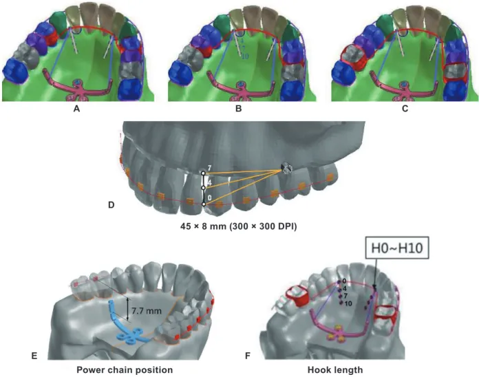
Four different distalization modalities were in- stalled and fifteen different models were produced on finite element models relative to the vertical position of the anterior hook and length of the pal- atal retraction arch (Figure 2).
Distalization Modality 1
Models 1-4 (Figure 2A); the MCPPs (Jeil Med- ical, Seoul, Korea) were fixed in the paramedian palatal region at the sagittal level of the center of the first molar with three miniscrews (length, 8 mm; diameter, 2 mm; Jeil Medical). In the mod- el, short stainless steel (SS) palatal retraction arch (PRA), 1.0 mm in diameter, was connected to the bands of the maxillary first premolars, extending anteriorly close to the level of the cervical line of the maxillary teeth. A Roth 0.022-inch bracket system (Tomy, Tokyo, Japan) was attached to the teeth and a 0.019 × 0.025-inch SS archwire was tied through frictionless translational joints and cinched-back on the second molar. Distalization forces of 300 g were applied via coil springs con- nected to the second notch on the arms of MCPPs (selected for force application and 7.7 mm api- cal to the archwire vertically and 12.5 mm later- al to the mid-palate horizontally) with the hook attached to the PRA at 0 mm length (Figure 2E, F). Models 2-4 were similar to Model 1, but the hook was attached to the PRA at 4, 7, and 10 mm lengths respectively.
Figure 1. Boundary condition. A, Fixed area, red surface; zygomaticomaxillary suture, frontonasal suture, palatomaxillary suture, pterygomaxillary suture. B, Three axes; x-axis, anterior (+) to posterior (-) direction; y-axis, median (+) to lateral (-) direction; and z-axis, superior (+) to inferior (-) direction.
B A
Figure 2. Installation of simulated distalization modalities on finite element model 45 × 8 mm (300 × 300 DPI). A, Modality 1, first premolar as the location of force application using MCPP. B, Modality 2, second premolar as the location of force application using MCPP. C, Modality 3, first molar as the location of force application using MCPP. D, Modality 4. E, F, The position of the MCPP and retraction hook 45 × 20 mm (300 × 300 DPI). E, Device (MCPP) position was assumed to be at the level of the first molar centers, antero-posteriorly. The second notch on the lever arms of the MCPP was selected for force application. A hook attached to the PRA between the lateral incisor and canine cingulum. F, Length of the retraction hook was determined at 0 mm (H0), 4 mm (H4), 7 mm (H7), and 10 mm (H10) from the connection point on the PRA.
B
A C
D
Power chain position Hook length
F E
45 × 8 mm (300 × 300 DPI)
Distalization Modality 2
Model 5-8 (Figure 2B); this modality was sim- ilar to Modality 1, but a medium length PRA was attached to the banded second premolar. Models 5-8 each included the hook attached to the PRA at 0, 4, 7, and 10 mm length respectively.
Distalization Modality 3
Models 9-12 (Figure 2C); this modality was sim- ilar to Modalities 1 and 2 but a long length PRA was attached to the banded first molar. Models 9-12 each included the hook attached to the PRA at 0, 4, 7, and 10 mm length respectively.
Distalization Modality 4
Models 13-15 (Figure 2D); brackets were placed on all teeth. A 0.019 × 0.025-inch SS archwire was engaged and cinched-back on the second molar.
For distalization, 300 g of force was applied on each side with a coil spring between the minis- crew and a 0.8 mm SS retraction hook attached to the archwire between the lateral incisor and ca- nine. The vertical height of the hook was set at 0, 4, and 7 mm on Models 13, 14, and 15 respectively.
The miniscrew position was set at 8 mm apical to the archwire, at the midpoint between the adjacent brackets.
RESULTS
The effects relative to the location of force applied using MCPP
In all models with MCPPs, mesial-in rotation of the PRA banded teeth was observed (Figure 3).
Distalization with Modality 1
The short length PRA showed an uncontrolled tipping pattern with the greatest distal displace- ment of the crown and mesial displacement of the root at 0 mm hook. As the hook length increased,
the distal movement of the root apex increased.
The first molar showed uncontrolled distal crown tipping with the hook at 0 mm. However, as the hook length increased, it showed gradually ante- rior displacement of the crown and posterior dis- placement of the root apex (Table 1).
Distalization with Modality 2
The medium length PRA showed severe un- controlled distal crown tipping with the hook at 0 mm. However, with the hook at 7 mm, it was clos- er to bodily movement. With the hook at 10 mm, there was a greater distal displacement of the root apex with mesial displacement of the crown. In the first molar area, the movement pattern was near- ly bodily movement with the hook at 0 mm. As the hook length increased, the first molar showed more extrusion with anterior displacement of the crown and posterior displacement of the root apex (Table 2).
Distalization with Modality 3
The long length PRA showed distal displace- ment of the crown and root with controlled dis- tal crown tipping with the hook at 0 mm. As the length of the hook increased, the posterior dis- placement of the crown decreased, and it was clos- er to bodily movement at 7 mm. In the z-axis, the first molar was intruded with the hook at 0 and 4 mm, but it was more extruded as the length of the hook increased (Table 3).
The effects relative to the vertical
position of the force applied using buccal miniscrews
Distalization with Modality 4
The incisors showed the greatest backward movement of the crown with anterior root tipping at the 0 mm hook. As the length of the hook in- creased, the posterior displacement of the crown
Figure 3. Three treatment modalities included a short length PRA (first premolar), a medium-length PRA (second premolar), and a long length PRA (first molar). And they were divided into 12 models relative to a hook length of 0 mm (H0), 4 mm (H4), 7 mm (H7), and 10 mm (H10). Tooth movement was expressed in three axes [x axis, anterior (+) to posterior (-) direction; y-axis, median (+) to lateral (-) direction; and z-axis, superior (+) to inferior (-) direction]. The arrows mean the line of retraction forces.
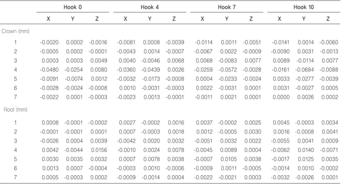
Table 1. Displacement by modality 1 with a short length PRA using MCPP
Hook 0 Hook 4 Hook 7 Hook 10
X Y Z X Y Z X Y Z X Y Z
Crown (mm)
1 -0.0020 0.0002 -0.0016 -0.0081 0.0008 -0.0039 -0.0114 0.0011 -0.0051 -0.0141 0.0014 -0.0060 2 -0.0005 0.0002 -0.0001 -0.0043 0.0014 -0.0007 -0.0067 0.0022 -0.0009 -0.0090 0.0031 -0.0013 3 0.0003 0.0003 0.0049 0.0040 -0.0046 0.0068 0.0068 -0.0083 0.0077 0.0089 -0.0114 0.0077 4 -0.0480 -0.0254 0.0080 -0.0360 -0.0439 0.0026 -0.0259 -0.0572 -0.0028 -0.0161 -0.0684 -0.0088 5 -0.0091 -0.0074 0.0012 -0.0032 -0.0173 -0.0008 0.0004 -0.0233 -0.0024 0.0033 -0.0277 -0.0039 6 -0.0028 -0.0024 -0.0008 0.0010 -0.0031 -0.0003 0.0022 -0.0031 0.0001 0.0031 -0.0027 0.0005 7 -0.0022 0.0001 -0.0003 -0.0023 0.0013 -0.0001 -0.0011 0.0021 0.0001 0.0000 0.0026 0.0002 Root (mm)
1 0.0008 -0.0001 -0.0002 0.0027 -0.0002 0.0016 0.0037 -0.0002 0.0025 0.0045 -0.0003 0.0034 2 -0.0001 -0.0001 0.0001 0.0007 -0.0003 0.0018 0.0012 -0.0005 0.0030 0.0016 -0.0008 0.0041 3 -0.0026 0.0004 0.0039 -0.0042 0.0020 0.0032 -0.0051 0.0032 0.0022 -0.0055 0.0041 0.0009 4 0.0042 -0.0044 0.0156 -0.0010 0.0024 0.0078 -0.0045 0.0089 0.0004 -0.0062 0.0140 -0.0071 5 0.0030 0.0035 0.0032 0.0007 0.0078 0.0038 -0.0007 0.0105 0.0038 -0.0017 0.0125 0.0035 6 0.0013 0.0007 -0.0004 -0.0003 0.0010 -0.0006 -0.0009 0.0011 -0.0005 -0.0014 0.0010 -0.0002 7 0.0005 -0.0003 0.0002 -0.0009 -0.0014 0.0004 -0.0022 -0.0021 0.0003 -0.0032 -0.0026 0.0001 X: sagittal (+), anterior, (-), posterior, Y: transversal, (+), palatal, (-), buccal, Z: vertical, (+), intrusion, (-), extrusion. *Short length PRA means force applied through first premolar using MCPPs.
Table 2. Displacement by modality 2 with a medium length PRA using MCPP
Hook 0 Hook 4 Hook 7 Hook 10
X Y Z X Y Z X Y Z X Y Z
Crown (mm)
1 -0.0038 0.0005 -0.0018 -0.0066 0.0009 -0.0030 -0.0069 0.0009 -0.0033 -0.0069 0.0010 -0.0034 2 -0.0031 0.0017 -0.0020 -0.0062 0.0034 -0.0032 -0.0073 0.0040 -0.0036 -0.0079 0.0043 -0.0038 3 -0.0006 0.0006 -0.0013 -0.0026 0.0021 -0.0018 -0.0036 0.0029 -0.0018 -0.0045 0.0036 -0.0017 4 0.0030 -0.0059 0.0065 0.0058 -0.0129 0.0056 0.0079 -0.0182 0.0042 0.0092 -0.0215 0.0028 5 -0.0300 -0.0167 0.0241 -0.0187 -0.0411 0.0131 -0.0054 -0.0620 -0.0010 0.0079 -0.0757 -0.0116 6 -0.0006 -0.0120 0.0008 0.0060 -0.0180 -0.0001 0.0086 -0.0221 -0.0011 0.0104 -0.0243 -0.0017 7 -0.0024 0.0014 -0.0011 -0.0054 0.0026 -0.0011 -0.0052 0.0042 -0.0006 -0.0050 0.0052 -0.0001 Root (mm)
1 0.0012 -0.0001 0.0007 0.0022 -0.0002 0.0015 0.0023 -0.0003 0.0014 0.0024 -0.0003 0.0014 2 0.0012 -0.0008 0.0003 0.0022 -0.0014 0.0013 0.0024 -0.0016 0.0016 0.0026 -0.0018 0.0019 3 0.0007 -0.0005 -0.0007 0.0014 -0.0010 0.0000 0.0016 -0.0013 0.0005 0.0017 -0.0015 0.0010 4 -0.0032 0.0027 0.0055 -0.0037 0.0053 0.0042 -0.0039 0.0073 0.0024 -0.0038 0.0086 0.0009 5 0.0088 -0.0042 0.0262 0.0033 0.0108 0.0225 -0.0052 0.0265 0.0150 -0.0136 0.0343 0.0084 6 -0.0005 0.0048 0.0002 -0.0028 0.0065 -0.0021 -0.0038 0.0076 -0.0037 -0.0045 0.0081 -0.0048 7 0.0001 -0.0013 -0.0004 0.0002 -0.0021 0.0004 -0.0003 -0.0027 0.0011 -0.0005 -0.0029 0.0016 X: sagittal (+), anterior, (-), posterior, Y: transversal, (+), palatal, (-), buccal, Z: vertical, (+), intrusion, (-), extrusion. *Medium length PRA means force applied through secondS premolar using MCPPs.
decreased. In the z-axis, only the crown of the cen- tral incisor was intruded with the hook at 0 mm, but as the length of the hook increased, the inci- sors showed more extrusion movement. In the first molars, as the length of the hook increased, the posterior movement of the crown increased with increased forward movement of the roots. In the z-axis, the intrusion of the first molar increased as the length of the hook increased. With transverse displacement, the anterior teeth and first premolar showed palatal displacement, but the second pre- molar and molars had lateral displacement in the hook at 0 mm (Figure 4, Table 4).
DISCUSSION
Buccal miniscrews have been applied as a sta- tionary anchorage for total maxillary arch distal- ization in non-extraction treatment. However, the risk of root damage due to narrow interradicu-
lar space led us to consider the use of the palatal plate. This study was conducted to biomechanical- ly analyze tooth movement depending on differ- ent PRAs using MCPPs during total arch distal- ization.
In a finite element study, Von-mises stress is ex- pressed by the sum of pressure, elongation, and torsion, so there is a limit to express the effects of orthodontic force over time. Therefore, our study only focused on the pattern of teeth displacement to evaluate tooth movement affected by PRA types during distalization of the maxillary denti- tion using MCPPs.
Depending on the location of force applied, dis- placement of the maxillary dentition showed un- controlled distal crown tipping of the first and sec- ond premolars with forward movement of the root in a short and medium-length PRA. This might be because the line of force of short and medi- um-length PRA passed far from the center of re-
7 -0.0064 -0.0046 -0.0010 -0.0068 -0.0066 -0.0012 -0.0060 -0.0079 -0.0011 -0.0064 -0.0092 -0.0015 Root (mm)
1 0.0015 -0.0001 0.0015 0.0020 -0.0001 0.0019 0.0021 -0.0002 0.0020 0.0025 -0.0002 0.0025 2 0.0014 -0.0008 0.0011 0.0019 -0.0012 0.0015 0.0021 -0.0013 0.0015 0.0025 -0.0015 0.0018 3 0.0013 -0.0009 0.0007 0.0018 -0.0013 0.0010 0.0020 -0.0015 0.0011 0.0024 -0.0018 0.0014 4 0.0002 0.0001 0.0003 0.0000 0.0004 0.0006 0.0000 0.0005 0.0008 0.0000 0.0004 0.0011 5 -0.0006 0.0024 0.0039 -0.0016 0.0061 0.0049 -0.0022 0.0084 0.0053 -0.0027 0.0102 0.0054 6 -0.0134 -0.0032 0.0081 -0.0145 0.0018 0.0019 -0.0152 0.0060 -0.0037 -0.0153 0.0106 -0.0100 7 0.0014 0.0013 -0.0001 0.0010 0.0017 -0.0005 0.0005 0.0020 -0.0008 0.0005 0.0023 -0.0013 X, sagittal (+), anterior, (-), posterior; Y, transversal, (+), palatal, (-), buccal; Z, vertical, (+), intrusion, (-), extrusion. *Long length PRA means force applied through first molar using MCPPs.
Figure 4. Fourth treatment modality using a buccal miniscrew divided into three models relative to a hook length 0 mm (H0), 4 mm (H4), and 7 mm (H7). The arrows mean the line of retraction forces.
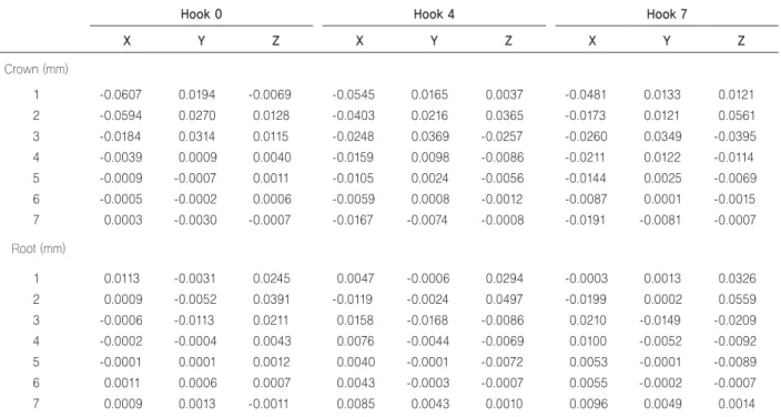
Table 4. Displacement by modality 4 according to hook length using buccal miniscrews
Hook 0 Hook 4 Hook 7
X Y Z X Y Z X Y Z
Crown (mm)
1 -0.0607 0.0194 -0.0069 -0.0545 0.0165 0.0037 -0.0481 0.0133 0.0121
2 -0.0594 0.0270 0.0128 -0.0403 0.0216 0.0365 -0.0173 0.0121 0.0561
3 -0.0184 0.0314 0.0115 -0.0248 0.0369 -0.0257 -0.0260 0.0349 -0.0395
4 -0.0039 0.0009 0.0040 -0.0159 0.0098 -0.0086 -0.0211 0.0122 -0.0114
5 -0.0009 -0.0007 0.0011 -0.0105 0.0024 -0.0056 -0.0144 0.0025 -0.0069
6 -0.0005 -0.0002 0.0006 -0.0059 0.0008 -0.0012 -0.0087 0.0001 -0.0015
7 0.0003 -0.0030 -0.0007 -0.0167 -0.0074 -0.0008 -0.0191 -0.0081 -0.0007
Root (mm)
1 0.0113 -0.0031 0.0245 0.0047 -0.0006 0.0294 -0.0003 0.0013 0.0326
2 0.0009 -0.0052 0.0391 -0.0119 -0.0024 0.0497 -0.0199 0.0002 0.0559
3 -0.0006 -0.0113 0.0211 0.0158 -0.0168 -0.0086 0.0210 -0.0149 -0.0209
4 -0.0002 -0.0004 0.0043 0.0076 -0.0044 -0.0069 0.0100 -0.0052 -0.0092
5 -0.0001 0.0001 0.0012 0.0040 -0.0001 -0.0072 0.0053 -0.0001 -0.0089
6 0.0011 0.0006 0.0007 0.0043 -0.0003 -0.0007 0.0055 -0.0002 -0.0007
7 0.0009 0.0013 -0.0011 0.0085 0.0043 0.0010 0.0096 0.0049 0.0014
X: sagittal (+), anterior, (-), posterior, Y: transversal, (+), palatal, (-), buccal, Z: vertical, (+), intrusion, (-), extrusion.
second premolar, and first molar, and the acting point of the actual force is on each tooth. There- fore, although the line of force is parallel, the point of force is different depending on the type of tooth. So, the distance between each line of force and the CR of the entire maxillary dentition is al- so different.
Also, the tooth movement pattern is clinical- ly influenced by the archwire size and the line of force. When the maxillary dentition is connected as one unit by a rigid archwire, the line of force is the same. However, in this study, the wire size was set to 19 × 25 SS, which could allow slight move- ment of individual teeth; results were shown ac- cording to variables in Figure 3A.
Additionally, the small root surface area of the first and second premolars play an important role in tipping movement. Choy et al.26 suggested that the tooth tipping tendency was associated with the amount of root surface area and demonstrated that roots with the greater surface area had greater re- sistance to tipping.
On the other hand, the long length PRA, Mo- dality 3, with the hook at 0 mm showed distal displacement with controlled crown tipping and intrusion. Also, hook at 7 mm was closer to trans- lation movement. Therefore, Modality 3, which used the first molar as the point of force applica- tion, was the most effective way for distalizing the maxillary dentition without uncontrolled tipping.
This result is similar with previous studies that re- ported distalization with MCPPs showed bodily
the retraction hook on the PRA, the direction of the force vector was determined via two points.
One was on the lever arm of the MCPP while the other was on the hook of the PRA. Previous re- search found that when 4, 7, and 10 mm notches were vertically apical to the archwire, the 4 mm notch showed controlled distal tipping and extru- sion, but the 10 mm notch caused bodily move- ment and intrusion.18 In our study, the force was only applied from the 7 mm notch on the MCPP to different vertical positions of the anterior hook on the PRA. The 7 mm notch on the MCPP was selected based on a previous study.18
The first molar was intruded when the short hook length was 0 and 4 mm. However, there was extrusion with the long hook at 7 and 10 mm. This could be because the direction of the force vector was below the CR in a low-level hook and above the CR in a high-level hook. As the force vector varies according to the length of the hook, the di- rection of the vector may change, which may cause an intrusive force.
With Modality 4, using a buccal miniscrew, the first molar showed uncontrolled distal crown tip- ping in different hook lengths. Our results were similar with an earlier study that reported uncon- trolled distal tipping of the first molar and extru- sion when buccal miniscrews were used.18 Sung et al.27 concluded that when force was applied to over 10 mm hook level, it led to the distal translation of the posterior segment, but in our study, over 7 mm level caused distal tipping. This might be due to a
difference in experimental designs and conditions used in the finite element analysis.
Regarding the y-axis, the second premolars and molars showed buccal tipping with the hook at 0 mm due to increased vertical component of the force on the buccal side, possibly just because of the buccal component of force created by the miniscrew positioned on the buccal side.
Clinically, Bechtold et al.5 suggested an addi- tional miniscrew in the premolar area to enhance the direction of the force vector and to facilitate intrusion and distalization of the entire arch. How- ever, a recent clinical study reported that MCPPs showed greater distalization and intrusion with less distal tipping of the first molar and less ex- trusion of the incisor compared to buccal minis- crews.10
The design of this study had some limitations as follows; only initial tooth displacement was con- sidered, no occlusal force was applied, there were differences in the mechanical properties of the virtual models and biological tissue. The thick- ness of the periodontal ligament was supposed to be uniform (0.25 mm), while in reality it was shaped with the narrowest zone at the mid-root level.21 Lastly, molar distalization with MCPPs is usually started at the same time as leveling and aligning with a 0.016-inch Ni-Ti archwire. How- ever, the archwire used in this study was a 0.019 × 0.025-inch SS archwire with cinch-back to avoid space opening during total arch distalization. In reality, with a properly angled tooth in a posteri- or crowding case, cinch-back is not necessary to relieve the crowding during molar distalization.
Further study about tooth displacement patterns and stress distribution using a 0.016 in Ni-Ti arch- wire in posterior crowding cases is required for efficient clinical applications with MCPPs.
CONCLUSION
This study evaluated the effects relative to the vertical position of the anterior hook and second- ly analyzed the pattern of the maxillary dentition displacement on distalization force applied by us- ing the palatal plate according to the location of the force applied, and compared those done by buccal miniscrew using finite element analysis.
The locations of force application were first, sec- ond premolar and first molar, which were attached to short, medium, and long length PRA respec- tively. We made the following observations: first, a long-length PRA using an MCPP showed bodily movement of the first molars. However, short and medium-length PRAs caused uncontrolled distal tipping. Second, displacement of the first molars using long length PRA with a short hook led to in- trusion. However, the long hook caused the extru- sion. Third, displacement of the first molars using short length PRA with a short hook led to extru- sion, and the long hook caused intrusion.
Therefore, this information should be useful when applying TSADs during total arch distaliza- tion.
Acknowledgments
The authors would like to thank Dr. Jung Mee Kim, Private practice, Los Angeles, California, USA, Dr. Jiyoung Oh, Resident, Department of Orthodontics, Seoul St. Mary’s Hospital, Catholic University of Korea, Seoul, Korea, and Jin Hyeok Kook, College of Dentistry, Yonsei University for their assistance in manuscript preparation.
REFENRENCES
1. Joseph AA, Butchart CJ. An evaluation of the pendu- lum distalizingappliance. Semin Orthod 2000;6:129-
croimplant-aided sliding mechanics on distal re- traction of posterior teeth. Am J Orthod Dentofacial Orthop 2011;139:470-481. https://doi.org/10.1016/j.ajo- do.2009.05.037
5. Bechtold TE, Kim JW, Choi TH, Park YC, Lee KJ. Dis- talization pattern of the maxillary arch depending on the number of orthodontic miniscrews. Angle Orthod 2013;83:266-273. https://doi.org/10.2319/032212-123.1 6. Kinzinger GS, Gülden N, Yildizhan F, Diedrich PR. Ef-
ficiency of a skeletonized distal jet appliance support- ed by miniscrew anchorage for noncompliance max- illary molar distalization. Am J Orthod Dentofacial Orthop 2009;136:578-586. https://doi.org/10.1016/j.ajo- do.2007.10.049
7. Kook YA, Kim SH, Chung KR. A modified palatal an- chorage plate for simple and efficient distalization. J Clin Orthod 2010;44:719-730; quiz 743.
8. Park JH, Saito T, Yoo SK, Alfaifi M, Kook YA. Dis- talization with a modified C-palatal plate for severe upper crowding and a missing lower incisor. Kore- an J Orthod 2020;50:52-62. https://doi.org/10.4041/
kjod.2020.50.1.52
9. Han SH, Park JH, Jung CY, Kook YA, Hong M. Full- step Class II correction using a modified C-palatal plate for total arch distalization in an adolescent. J Clin Pedi- atr Dent 2018;42:307-313. https://doi.org/10.17796/1053- 4628-42.4.13
10. Lee SK, Abbas NH, Bayome M, Baik UB, Kook YA, Hong M, Park JH. A comparison of treatment effects of total arch distalization using modified C-palatal plate vs buccal miniscrews. Angle Orthod 2018;88:45-51.
https://doi.org/10.2319/061917-406.1
11. Kook YA, Bayome M, Trang VT, Kim HJ, Park JH, Kim KB, Behrents RG. Treatment effects of a modified palatal anchorage plate for distalization evaluated with cone-beam computed tomography. Am J Orthod Dento-
fied C-palatal plate. Korean J Orthod 2018;48:224-235.
https://doi.org/10.4041/kjod.2018.48.4.224
14. Shoaib AM, Park JH, Bayome M, Abbas NH, Alfaifi M, Kook YA. Treatment stability after total maxillary arch distalization with modified C-palatal plates in adults.
Am J Orthod Dentofacial Orthop 2019;156:832-839.
https://doi.org/10.1016/j.ajodo.2019.01.021
15. Park JH, Kook YA, Kojima Y, Yun S, Chae JM. Pala- tal en-masse retraction of segmented maxillary anteri- or teeth: a finite element study. Korean J Orthod 2019;
49:188-193. https://doi.org/10.4041/kjod.2019.49.3.188 16. Hong RK, Heo JM, Ha YK. Lever-arm and mini-im-
plant system for anterior torque control during retrac- tion in lingual orthodontic treatment. Angle Orthod 2005;75:129-141. https://doi.org/10.1043/0003-3219(200 5)075<0129:LAMSFA>2.0.CO;2
17. Seo KW, Kwon SY, Kim KA, Park KH, Kim SH, Ahn HW, Nelson G. Displacement pattern of the anterior seg- ment using antero-posterior lingual retractor combined with a palatal plate. Korean J Orthod 2015;45:289-298.
https://doi.org/10.4041/kjod.2015.45.6.289
18. Yu IJ, Kook YA, Sung SJ, Lee KJ, Chun YS, Mo SS.
Comparison of tooth displacement between buccal mini-implants and palatal plate anchorage for mo- lar distalization: a finite element study. Eur J Orthod 2014;36:394-402. https://doi.org/10.1093/ejo/cjr130 19. Coolidge ED. The thickness of the human periodontal
membrane. J Am Dent Assoc Dent Cosm 1937;24:1260- 1270. https://doi.org/10.14219/jada.archive.1937.0229 20. Block PL. Restorative margins and periodontal health:
a new look at an old perspective. J Prosthet Dent 1987;57:683-689. https://doi.org/10.1016/0022-3913(87) 90363-5.
21. Tanne K, Sakuda M, Burstone CJ. Three-dimension- al finite element analysis for stress in the periodontal tissue by orthodontic forces. Am J Orthod Dentofacial
Orthop 1987;92:499-505. https://doi.org/10.1016/0889- 5406(87)90232-0
22. Sung SJ, Kim IT, Kook YA, Chun YS, Kim SH, Mo SS. Finite-element analysis of the shift in center of re- sistance of the maxillary dentition in relation to alve- olar bone loss. Korean J Orthod 2009;39:278. https://
doi.org/10.4041/kjod.2009.39.5.278
23. Kang JM, Park JH, Bayome M, Oh M, Park CO, Kook YA, Mo SS. A three-dimensional finite element analy- sis of molar distalization with a palatal plate, pendulum, and headgear according to molar eruption stage. Kore- an J Orthod 2016;46:290-300. https://doi.org/10.4041/
kjod.2016.46.5.290
24. Jeong GM, Sung SJ, Lee KJ, Chun YS, Mo SS. Fi- nite-element investigation of the center of resistance of the maxillary dentition. Korean J Orthod 2009;39:83-
94. https://doi.org/10.4041/kjod.2009.39.2.83
25. Stockli PW, Teuscher UM. Combined activator head- gear orthopedics. In: Graber TM, Vanarsdall RL, edi- tors. Orthodontics: Current Principles and Techniques.
2nd ed. St. Louis, Mo: Mosby; 1994, p. 448.
26. Choy K, Pae EK, Park Y, Kim KH, Burstone CJ. Effect of root and bone morphology on the stress distribution in the periodontal ligament. Am J Orthod Dentofacial Orthop 2000;117:98-105. https://doi.org/10.1016/s0889- 5406(00)70254-x
27. Sung EH, Kim SJ, Chun YS, Park YC, Yu HS, Lee KJ. Distalization pattern of whole maxillary den- tition according to force application points. Kore- an J Orthod 2015;45:20-28. https://doi.org/10.4041/
kjod.2015.45.1.20
Dr. 장 나 영 Dr. 채 종 문
Dr. 이 영 준 Dr. 김 태 균
Corresponding author: Na-Young Chang Department of Orthodontics, Wonkwang University Daejeon Dental Hospital,
77 Dunsan-ro, Seo-gu, Daejeon 35233, Korea Tel: +82-42-366-1192 E-mail: [email protected] Received: February 11, 2021 / Revised: February 22, 2021 / Accepted: February 22, 2021
ABSTRACT
Face mask treatment with a rapid palatal expander is common in children with Class III malocclusion and maxillary deficiency. However, it can cause anchorage loss and dental side effects. To overcome these disadvantages, the use of skeletal anchorage such as miniplates in the infrazygomatic crest area or palate has been reported. This clinical case report presents face mask treatment in skeletal Class III adolescent with maxillary skeletal expander (MSE). MSE has been developed for the maxillary expansion in adults, but it can be used as a skeletal anchorage for face mask treatment in children. The post-treatment profile was significantly improved without any dental side effects. (Clin J Korean Assoc Orthod 2021;11(2):102-114)
Key words Active plate, Maxillary skeletal expander, Face mask, Class III malocclusion
Treatment of a Growing Patient with Skeletal Class III Malocclusion Using Face Mask and Maxillary Skeletal Expander
Tae-Gyun Kim,1 Young-Jun Lee,1 Jong-Moon Chae,1,2,3 Na-Young Chang1,2
1Department of Orthodontics, School of Dentistry, University of Wonkwang, Iksan, Korea
2Wonkwang Dental Research Institute, Iksan, Korea
3Postgraduate Orthodontic Program, Arizona School of Dentistry & Oral Health, A.T. Still University, Mesa, Arizona, USA
서론
상악골 열성장을 동반한 골격성 III급 반대교합을 보 이는 성장기 아동에서 상악골의 전방 견인을 위해 페이 스 마스크가 사용되어 왔다.1 페이스 마스크 장치와 함 께 구강 내 장치로 접착형 혹은 밴드형의 상악 급속 확 장장치(rapid maxillary expander; RME)가 주로 사 용되는데, 이는 상악궁 확장과 동시에 전방 견인을 효 과적으로 하기 위함이다.2 Baik3은 60명의 한국 아동 을 대상으로 상악궁 확장 시 전방 견인이 더 잘 일어남 을 확인했고 J¨ager 등4은 메타 분석으로 RME를 사용 하고 상악 전방 견인을 하면 더 큰 효과가 있음을 입증 했다. 하지만 이러한 전통적인 페이스 마스크 치료는 전 치부를 순측 경사 시키고 상악 구치부를 정출 및 협측 경사 시킨다.5
골성 고정원과 함께 페이스 마스크를 사용하기 시작 하면서 이러한 치성 부작용을 최소화할 수 있게 되었 다. Cha 등6은 관골하능(infrazygomatic crest)에 미 니 플레이트를 식립하여 페이스 마스크의 고정원으로 사용하는 방법을 제시하였는데, 이는 부가적인 외과적 술식이 필요하다는 단점이 있다. 또한 Kook 등7은 구개 에 미니 임플랜트를 식립하여 고정원으로 이용하였으나 상악의 횡적 부조화가 있는 경우 이를 개선하기 어렵다 는 단점이 있다.
상악 골격성 확장장치[maxillary skeletal exp
ander (MSE); BioMaterials Korea Inc., Seoul, Korea]는 원래 성인에서 구개 확장을 위한 장치로 개발 되었으나, 성장기 아동에서 전방 견인 치료 시 골성 고 정원 장치로 활용할 수 있다.8,9 이번 증례보고에서는 상 교정장치(active plate) 및 MSE와 페이스 마스크를 이 용하여 골격성 III급 성장기 아동을 성공적으로 치료하 였음을 보고하는 바이다.
진단
9세 1개월의 남자 환자가 전치부 반대교합을 주소로 의뢰되었다. 전신 및 치과적 병력상 특이사항은 없었다.
보호자의 진술에 의하면 외가 쪽으로 하악 발달 경향의 가족력이 있다고 하였다.
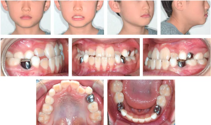
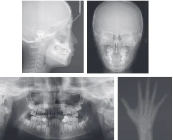
초진 시 정모에서 이부의 우측 변위가 관찰되며, 미소 시 상악 전치의 노출은 부족하였다. 상악 치열의 정중 선은 안모 정중선과 일치하였다. 측모에서는 오목형 안 모를 보이고 있었고 하순 및 턱끝 돌출감이 있었다. 구 내 사진 및 진단 모형에서 전치부 및 우측 구치부 반대 교합을 보였고 그로 인한 하악 치열 정중선의 변위 및 상악 전치부의 크라우딩이 관찰되었다(Figures 1, 2).
측면 두부계측방사선사진에서 전후방적으로는 골격 성 III급 부정교합(ANB: 1.4°, A pointN perpend:
0.8 mm, PogN perpend: 1.5 mm)을, 수직적으로 는 저발산형의 경향(FMA: 18.2°, ODI: 68.7°)을 보였 다. 상악 전치의 경사도(U1 to FH: 117.9°)와 하악 전치 의 경사도(IMPA: 93.3°)는 정상 범주였다(Table 1). 정 면 두부계측방사선사진에서는 이부(Me)가 우측으로 변 위되어 있었다. 파노라마방사선사진상에서 견치 및 소 구치는 치근 형성 단계였고 수완부 방사선사진상 SMI 1단계로 판단되었다. 콘빔 전산화단층촬영 영상은 삼차 원 소프트웨어(ON3D; 3DONS, Seoul, Korea)로 분 석하였다. 상악은 전후방적으로 열성장[A(y): 1.71; 정 상 범위, 0~2]을 보였으며, 하악은 전후방적으로 정 상[Pog(y): 1.14; 정상 범위, +40]이었다(Figure 3, Table 2).
이에 본 환자는 저발산형의 골격 패턴과 전치부, 구치 부 반대교합을 동반한 골격성 III급 부정교합으로 진단 하였다.
Figure 2. Pretreatment dental casts.
Figure 1. Pretreatment facial and intraoral photographs.
치료계획
초진 시 상악의 좁은 폭경으로 인한 반대교합을 나 타내고 있었으므로 상악의 폭경 확장을 우선적으로 고 려하였다. 상악 확장을 위한 계획으로는 (1) 상교정장치 (active plate)를 이용한 확장, (2) 상악 급속 확장장치 (RME)를 이용한 확장, (3) MSE를 이용한 확장 등을 고려할 수 있다. 보호자가 안모의 변화를 원치 않았고 구외 장치의 사용을 거부하여 상교정장치(active plate) 를 통한 완속 확장 후 하악의 위치를 재평가한 후 필요 시 상악의 전후방적인 성장 결핍을 개선하기 위한 페이 스 마스크를 고려하기로 하였다.
치료경과 및 결과
치료과정
치료 시작으로 구치부 교합 블록(bite block)을 포함 한 상악 상교정장치를 통한 완속 확장을 시행하였다.
환자 스스로 스크루를 돌릴 수 있도록 교육하였고 환자 는 일주일에 1/4바퀴(0.25 mm)씩 스크루를 활성화하 였다(Figure 4A). 상악의 확장을 시작한 지 1달 만에 구치부 반대교합이 해소되면서 전치부 반대교합도 동시 에 개선됨을 확인하였다. 이때, 상악 좌측 측절치의 구 개측 변위로 인해 교합 간섭이 나타났고 이를 해소하기 위해 상악 전치부에 0.022inch 슬롯 브라켓(Master SeriesⓇ, MBT prescription)을 부착하여 배열하였다 (Figure 4B).
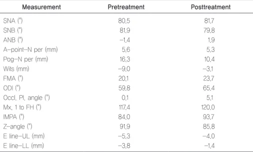
고정식 장치 부착 한 달 후 상악 좌측 측절치의 반대 교합이 해소되었으나, 하악 유견치 부분의 교합 간섭이 Table 1. Cephalometric measurements
Mesurements Mean Pretreatment Posttreatment
SNA (°) 81.0 80.2 81.2
SNB (°) 78.0 81.6 78.6
ANB (°) 4.0 -1.4 2.7
Wits (mm) -2.0 -8.2 -2.7
Mandibular body length (mm) 71.0 71.5 75.8
APDI (°) 82.0 92.7 85.5
Gonial angle (°) 126.0 113.9 113.3
Sum (°) 396.0 387.3 389.8
FMA (°) 26.0 18.2 21.6
Ramus height (mm) 43.0 47.0 47.0
Post/Ant (%) 61.0 71.9 69.5
SN-MP (°) 36.0 27.3 29.8
ODI (°) 72.0 68.7 78.8
U1 to SN (°) 105.0 108.8 110.0
U1 to FH (°) 116.0 117.9 118.2
IMPA (°) 95.0 93.3 93.0
Interincisal angle (°) 124.0 130.6 127.2
Upper lip EL (mm) 2.4 -0.4 1.9
Lower lip EL (mm) 3.3 2.0 1.9
Stmi-Me’/Sn-Stms (ratio) 2.0 2.2 2.0
Table 2. 3-dimensional coordinate values of the selected landmarks at the pretreatment, progress, and posttreatment Pretreatment After active plate treatment or
Pre-MSE + face mask Posttreatment
A (1.29, 1.71, -52.75) (1.17, 0.77, -54.37) (1.36, 0.52, -54.11)
Pog (0.96, 1.14, -96.26) (2.44, 1.36, -97.93) (4.17, 6.07, -99.61)
U1MP (4.03, 0.04, -70.18) (1.65, -2.57, -71.37) (2.25, -2.01, -73.12)
L1MP (0.65, -2.41, -70.29) (0.80, -0.10, -73.38) (2.57, 1.30, -70.52)
Pronasale (1.14, -18.56, -42.95) (0.30, -19.95, -43.00) (2.34, -20.73, -43.13)
MSE: maxillary skeletal expander, U1MP: upper dental midline point, L1MP: lower dental midline point.
Figure 3. Pretreatment radiographs.
관찰되어 전방부의 확장을 계획하였다. 이에 fan형 확 장 스크루(fantype expansion screw)를 갖는 상교 정장치로 변경하여 확장을 더 진행하였다(Figure 4C).
상악궁의 확장 및 상악 전치부의 순측 경사를 동반하 여 치료한 지 5개월 후 더 이상의 치성 간섭이 존재하 지 않았고 안정된 교합관계를 이루고 있음이 확인되었 다. 그러나 상악 전치부의 순측 경사 및 전치부에서 부 족한 수평피개를 보였고, 보호자가 이에 대한 개선을 원했다(Figure 4D). 완속 확장 후 보호자가 순측 경사 된 상악 전치의 수정을 원하였고 하악의 위치를 재평가 한 결과 오목형 안모를 보이고 전치부의 부족한 수평피 개를 보여 MSE를 이용한 페이스 마스크 치료를 시행하 였다.
전통적인 페이스 마스크를 사용할 경우 원치 않는 상 악 전치부 전방 경사나 크라우딩 등의 부작용이 예상 되었다. 따라서 골격성 고정원을 이용한 페이스 마스크
를 시행하기로 하였다. 골격성 고정원으로 MSE를 사 용하였다. 구개부에 4개의 스크루(직경 1.5 mm, 길이 11 mm; BioMaterials Korea Inc., Seoul, Korea)를 부분 마취하에 식립하였고, 기공 과정을 거쳐 레버암 을 견치 부위까지 연장하였다. 환아에게 3/16inch 5 oz 고무줄을 전하방 방향으로 걸도록 교육하여 편측당 300400 g의 힘으로 전방 견인을 시행하였다. MSE로 추가적인 확장은 필요하지 않아 진행하지 않았으며 페 이스 마스크를 사용하였다(Figure 5). MSE를 이용한 페이스 마스크를 8개월간 사용한 후 상악 전치부의 브 라켓을 제거하였고, 설측에 고정식 보정장치를 부착하 였다. 치료 16개월째에 MSE를 제거하였다.
치료결과
상교정장치로 확장 후 하악 위치의 재평가를 위해 콘 빔 전산화단층촬영 영상을 삼차원 소프트웨어(ON3D) Figure 4. Progress intraoral photographs: initial (A), 1 month (B), 4 months (C), 5 months (D).
A
B
C
D